EP0322502A2 - Dispositif pour déterminer des données d'une cible - Google Patents
Dispositif pour déterminer des données d'une cible Download PDFInfo
- Publication number
- EP0322502A2 EP0322502A2 EP88111177A EP88111177A EP0322502A2 EP 0322502 A2 EP0322502 A2 EP 0322502A2 EP 88111177 A EP88111177 A EP 88111177A EP 88111177 A EP88111177 A EP 88111177A EP 0322502 A2 EP0322502 A2 EP 0322502A2
- Authority
- EP
- European Patent Office
- Prior art keywords
- arrangement
- optical axis
- cylindrical lens
- modulator
- distance
- Prior art date
- Legal status (The legal status is an assumption and is not a legal conclusion. Google has not performed a legal analysis and makes no representation as to the accuracy of the status listed.)
- Granted
Links
Images


Classifications
-
- G—PHYSICS
- G01—MEASURING; TESTING
- G01S—RADIO DIRECTION-FINDING; RADIO NAVIGATION; DETERMINING DISTANCE OR VELOCITY BY USE OF RADIO WAVES; LOCATING OR PRESENCE-DETECTING BY USE OF THE REFLECTION OR RERADIATION OF RADIO WAVES; ANALOGOUS ARRANGEMENTS USING OTHER WAVES
- G01S3/00—Direction-finders for determining the direction from which infrasonic, sonic, ultrasonic or electromagnetic waves, or particle emission, not having a directional significance, are being received
- G01S3/02—Direction-finders for determining the direction from which infrasonic, sonic, ultrasonic or electromagnetic waves, or particle emission, not having a directional significance, are being received using radio waves
- G01S3/14—Systems for determining direction or deviation from predetermined direction
-
- G—PHYSICS
- G01—MEASURING; TESTING
- G01S—RADIO DIRECTION-FINDING; RADIO NAVIGATION; DETERMINING DISTANCE OR VELOCITY BY USE OF RADIO WAVES; LOCATING OR PRESENCE-DETECTING BY USE OF THE REFLECTION OR RERADIATION OF RADIO WAVES; ANALOGOUS ARRANGEMENTS USING OTHER WAVES
- G01S11/00—Systems for determining distance or velocity not using reflection or reradiation
- G01S11/02—Systems for determining distance or velocity not using reflection or reradiation using radio waves
Definitions
- An arrangement is known from US Pat. No. 4,634,230 in which bearings are determined by optical means as a function of the frequency of the received signals.
- An optical modulator arrangement as a scaled-down antenna arrangement is determined by the received signals of the on controlled individual elements of the receiving arrangement and delivers a light wave field that reflects the phase relationships of the received wave field.
- the modulator arrangement consists of acousto-optical single-sideband modulators, e.g. B. Bragg cells, which are arranged side by side in the longitudinal direction according to the configuration of the receiving arrangement and perpendicular to it acoustically controlled by the received signals.
- the parallel incident light beams leave the modulator arrangement in a plane which is determined by the longitudinal direction and the optical axis, at an angle which is caused by the phase shifts between the received signals.
- a plane perpendicular to this which is determined by the optical axis and the perpendicular to the longitudinal direction, the light beams are diffracted into different exit angles depending on the frequency of the received signals due to the Bragg diffraction.
- the emerging light beams are focused on an imaging plane.
- the angle of incidence of the received wave energy is depicted as a function of the frequency of the received signals.
- Such a modulator arrangement can be used particularly advantageously for high-frequency received signals, as are common, for example, in radar technology.
- German patent application P 37 39 101.1 describes an optical modulator arrangement consisting of individual optical single-sideband modulators for reception signals of lower frequency, which can be successfully used for reception signals in sonar technology, for example. With a subordinate spherical converging lens, however, only a bearing to the target is possible.
- the wavefront curved at the point of reception makes it difficult to find a bearing to the destination.
- the curvature of the wavefront is a measure of the distance between the destination and the place of reception.
- the advantage of the device according to the invention is, in particular, that both target data, namely distance and bearing, can be determined simultaneously without any computational effort using optical components.
- the wave field is transformed from the spatial region into the solid angle region by means of sheep adjustment and imaging with a single cylindrical lens, so that both target data are simultaneously available.
- Only two variables in the optical system enable the location of any number of targets, especially in the near field, namely firstly the distance or the focal length and secondly the storage of the image in the longitudinal direction of the modulator arrangement and perpendicular to the optical axis. With the device according to the invention, it is thus possible to locate an approaching target, particularly at a short distance, with great accuracy.
- the measurement data for determining the location of each target are determined by respective focusing, so that all targets are detected one after the other.
- Another great advantage of the device according to the invention according to claim 1 is that by focusing, interference signals from other distance ranges are suppressed, so that the useful / interference ratio is significantly improved.
- the particular advantage of the device according to the invention according to claim 3 is that when using a cylindrical lens with a fixed focal length, the detector arrangement need not be shifted, but the image on the inclined detector arrangement has a constriction, its distance from the cylindrical lens and its placement from the optical axis Bearing and distance Specify the destination. It is particularly advantageous that the focus is set automatically. Another advantage is that measurement data are available to several targets at the same time, without the need for one or more focus settings.
- a multichannel single-sideband modulator arrangement according to patent application P 37 39 101.1 is advantageously used as the modulator arrangement, with which any low-frequency received signals can also be modulated onto light as a carrier.
- the light wave field leaving the modulator arrangement exactly reproduces the wave fronts with respect to the shape and direction of incidence of the received acoustic wave energy in a plane spanned by the optical axis and longitudinal direction of the modulator arrangement.
- the reception frequencies are in a range that allows the use of Bragg cells lined up in the longitudinal direction as a modulator arrangement.
- the Bragg cells are driven by the received signals of the individual elements of the receiving arrangement.
- a second cylindrical converging lens is introduced into the beam path between the modulator arrangement and the cylindrical lens, the vertical axis of which is aligned parallel to the longitudinal direction and perpendicular to the optical axis and to the axis of the cylindrical lens.
- the cylindrical converging lens With the cylindrical converging lens, the light rays are focused in their focal plane.
- the focal plane is parallel to the detector arrangement. Stripes form that are parallel to the axis of the cylindrical lens. Its height indicates the frequency of the wave energy received.
- the cylindrical converging lens effects a frequency analysis of the received signals since the exit angles of the light beams leaving the modulator arrangement are frequency-dependent.
- one is free to choose the geometric arrangement of the cylindrical lens and the cylindrical converging lens, so that the structure can be adapted to the individual optical components available.
- the use of a point source with a downstream spherical lens according to claim 6 for expanding the light illuminating the modulator arrangement is also possible.
- the modulator arrangement is illuminated via a cylindrical lens which, according to the advantageous development according to claim 8, can also be exchanged for the cylindrical lens.
- the advantage of this arrangement according to claim 8 when using a cylindrical lens with a variable focal length in front of the modulator arrangement is, in particular, that the modulator arrangement, the cylindrical lens and the detector arrangement form a compact, one-off adjustment or an integrated optical module.
- the light illuminating the modulator arrangement is adjusted by varying the focal length of the cylindrical lens in such a way that the light beams leaving the modulator arrangement are parallel and form plane wavefronts.
- the near-field curvature of the wave energy received via the receiving arrangement is compensated for by oppositely curved wave fronts of the light illuminating the modulator arrangement.
- the compensation is effected by focusing the cylindrical lens and can be adjusted by the sharpness of the image.
- the advantage of the development of the device according to the invention according to claim 9 is that by inserting a prism into the optical arrangement, wave energy from a selected reception direction is imaged at a predetermined location, preferably in the middle, of the detector arrangement and is therefore easily recognizable.
- This optical signal processing is particularly advantageous for surveillance tasks in a sea area or in an air space.
- the phase response of the prism or its wedge angle is set by the geometric distribution of the individual elements along a straight line on the receiving arrangement and the selected receiving direction, taking into account the scale.
- the device according to the invention can also be used advantageously in a flat receiving arrangement.
- the individual elements are then divided into a grid of columns and rows and assigned to the columns and rows modulator arrangements.
- the cylindrical lens is replaced by a spherical lens.
- the image on the detector arrangement is then punctiform and no longer strip-shaped and provides a bearing angle in azimuth and elevation.
- phase plate according to the development according to the invention as claimed in claim 11 is in particular that target data can be determined optically quickly and reliably even when using receiving arrangements of any configuration, for example on curved lines or surfaces.
- the advantage of the development according to the invention according to claim 13 is, in particular, that a matrix of individual modulators as a phase plate can be controlled easily and is insensitive to temperature and can be adapted to different tasks with different reception arrangements.
- This location-dependent, optical phase compensation is then followed by a spatial frequency analysis for determining the direction using the cylindrical lens.
- "shading" of the received signals is advantageously carried out optically according to the development of the device according to the invention according to claim 15.
- An amplitude filter is inserted, for example, in front of the modulator arrangement in the beam path, the blackening distribution of which is scaled to the installation location of the individual elements on the receiving arrangement.
- optical fiber hydrophones of the interferometer type for example according to the Mach-Zehnder principle, are used in accordance with the advantageous development according to claim 16.
- Such fiber optic hydrophones are known, inter alia, from DE-OS 33 31 712.
- Each optical fiber hydrophone replaces the individual element and the associated single-sideband modulator, since the effect of the wave energy emitted by the target, namely the sound field, a change in refractive index and length in one optical fiber, which forms the measuring branch, compared to the second optical fiber, which forms the reference branch, and thus causes a phase shift.
- the light beam leaving the light guide hydrophone which is obtained by superimposing the two light waves in the measuring branch and in the reference branch, represents the phase of the received signal.
- the outputs of the optical fiber hydrophones are arranged to scale so that they emulate the receiving arrangement.
- the emerging light beams are fed to the cylindrical lens, for example via a downstream GRIN optic, or to the spherical lens in the case of a flat arrangement.
- the particular advantage of the device according to claim 16 is that the phase information of the received signals is transmitted to light directly by the light guide hydrophone itself and thus the light guide hydrophone encloses the modulator arrangement.
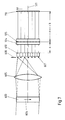
- FIG. 1 shows a planar receiving arrangement 10 which receives wave energy from a target 11 at a bearing angle ⁇ .
- the target 11 is located at a distance ⁇ from the receiving arrangement 10.
- the receiving arrangement 10 has seven individual receivers 21 to 27 on a straight line.
- the target 11 is located in the so-called close range of the receiving arrangement 10, namely at a distance that is smaller than the Fresnel limit for the near field.
- the Fresnel limit is determined by the length L of the receiving arrangement 10 and the frequency f or wavelength ⁇ of the received wave energy: ⁇ ⁇ 2.5. . If the target 11 is beyond the Fresnel limit, the receiving arrangement receives a flat wavefront. However, if the target 11 is in the near field, a curved, spherical wavefront is received, ie the received signals of the individual elements 21 to 27 do not grow linearly de phase shift against each other.
- the received signals of the seven individual elements 21 to 27 are optionally fed to seven single-sideband modulators of an optical modulator arrangement 100 after amplification and filtering.
- the single sideband modulators of the optical modulator arrangement 100 are arranged next to one another in the longitudinal direction 101 and are illuminated by coherent light 102.
- the optical axis 103 of the optical device, with which the bearing angle ⁇ and the distance ⁇ to the target 11 are determined, is perpendicular to the longitudinal direction 101.
- a cylindrical lens 104 is located on the optical axis 103; whose axis 105 is arranged perpendicular to the optical axis 103 and perpendicular to the longitudinal direction 101.
- the cylindrical lens 104 bundles incident parallel light in its focal plane, which is perpendicular to the optical axis 103.
- a spherical wave is received by the receiving arrangement 10. Since the received signals of the receiving arrangement 10 drive the modulator arrangement 100, the light leaving the modulator arrangement 100 likewise has curved wavefronts.
- the modulator arrangement 100 acts like a diverging lens which is illuminated with parallel light. The light leaving the modulator arrangement prepares itself as if a light source is in front of a diverging lens at a finite distance and forms a virtual light target. The light leaving the modulator arrangement 100 is focused by the cylindrical lens 104. A stripe is created which is then sharply imaged on the detector arrangement 110 when the detector arrangement 110 is at a greater distance than the focus distance from the cylindrical lens 104 and the optical image equation is satisfied.
- the displacement of the detector arrangement 110 from the focal distance to a larger distance must always be carried out when the target 11 enters the near field from the far field. From then on, an exact determination of the distance ⁇ to the target 11 is possible. As long as the target 11 is in the far field, the receiving arrangement 10 reaches a flat wavefront and the light leaving the modulator arrangement 100 also has a flat wavefront which is focused in the focal plane of the cylindrical lens 104 and leads there to a sharp strip-shaped image.
- the focus is centered on the detector arrangement 110, specifically perpendicular to the optical axis 103 as a strip parallel to the axis 105.
- the strip also moves in parallel to the longitudinal direction 101 on the detector arrangement 110.
- the filing from the middle is referred to with h.
- distance ⁇ and bearing ⁇ is simplified if the distance a between the cylindrical lens 104 and the modulator arrangement is chosen to be equal to the focal length z
- the measurement data h and x are determined one after the other by respective focusing.
- 3a, b shows a perspective and side view of an optical structure comprising a modulator arrangement 100, a cylindrical lens 104 and a detector arrangement 110.
- the detector arrangement 110 is not arranged perpendicular to the optical axis 103 in a plane which is parallel to the longitudinal direction 101 and the axis 105 of FIG Cylinder lens 104 is clamped, but at an angle of inclination ⁇ .
- the cylindrical lens 104 has a fixed focal length z.
- the upper edge of the detector arrangement 110 is located in the focal plane of the cylindrical lens 104.
- the strip shown in FIG. 1 has changed its shape due to the inclination of the detector arrangement and has a constriction 300 which supplies the measurement data h and z + x. Taking into account the angle of inclination ⁇ , the distance ⁇ and the bearing ⁇ to the target can then be determined again. Multiple destinations are displayed here simultaneously.
- FIG. 4 shows the top view of an expanded optical arrangement for monitoring tasks according to FIG. 2.
- the prism 310 has a wedge characterized by a wedge angle ⁇ in this plane.
- a preferred reception direction can be set by selecting the wedge angle ⁇ . Whenever a target appears under the bearing of this set receiving direction, a light streak will appear on the detector arrangement 110 in the middle.
- the detector arrangement 110 is arranged vertically here.
- FIG. 5 shows such an optical structure as a top view for a receiving arrangement following the arc of a circle with the individual elements 21 to 27 which control the modulator arrangement 100.
- the light leaving the modulator arrangement 100 is just as divergent as if the individual elements 21 to 27 of the receiving arrangement were arranged on the chord and not on the circular arc.
- the light beams are focused with the cylindrical lens 104 and imaged on the detector arrangement 110 after appropriate focusing.
- the modulator arrangement 600 is followed by a cylindrical converging lens 605, the vertical axis 606 of which is parallel to the longitudinal direction 602 of the modulator arrangement 600 and perpendicular to the optical axis 103.
- the cylindrical converging lens 605 focuses the light beams in a focal plane 607 in such a way that, depending on the frequency, a stripe pattern in the direction
Landscapes
- Physics & Mathematics (AREA)
- Engineering & Computer Science (AREA)
- General Physics & Mathematics (AREA)
- Radar, Positioning & Navigation (AREA)
- Remote Sensing (AREA)
- Optical Radar Systems And Details Thereof (AREA)
Applications Claiming Priority (2)
| Application Number | Priority Date | Filing Date | Title |
|---|---|---|---|
| DE19873744051 DE3744051A1 (de) | 1987-12-24 | 1987-12-24 | Vorrichtung zum bestimmen von zieldaten |
| DE3744051 | 1987-12-24 |
Publications (3)
| Publication Number | Publication Date |
|---|---|
| EP0322502A2 true EP0322502A2 (fr) | 1989-07-05 |
| EP0322502A3 EP0322502A3 (fr) | 1991-03-06 |
| EP0322502B1 EP0322502B1 (fr) | 1994-11-09 |
Family
ID=6343571
Family Applications (1)
| Application Number | Title | Priority Date | Filing Date |
|---|---|---|---|
| EP88111177A Expired - Lifetime EP0322502B1 (fr) | 1987-12-24 | 1988-07-13 | Dispositif pour déterminer des données d'une cible |
Country Status (2)
| Country | Link |
|---|---|
| EP (1) | EP0322502B1 (fr) |
| DE (2) | DE3744051A1 (fr) |
Families Citing this family (1)
| Publication number | Priority date | Publication date | Assignee | Title |
|---|---|---|---|---|
| DE4442400A1 (de) * | 1994-11-30 | 1996-06-05 | Imm Inst Mikrotech | Sensor zur Bestimmung der Lage im Raum |
Family Cites Families (4)
| Publication number | Priority date | Publication date | Assignee | Title |
|---|---|---|---|---|
| US4503382A (en) * | 1982-10-18 | 1985-03-05 | Litton Systems, Inc. | Method and device for centroid detection of a beam of electromagnetic energy |
| GB2183822A (en) * | 1984-11-12 | 1987-06-10 | Australia Dept Ind Defence | A mach-zehnder acousto-optic signal processor for electronic support measures |
| DE3445373A1 (de) * | 1984-12-13 | 1986-06-19 | Fried. Krupp Gmbh, 4300 Essen | Vorrichtung zur richtungsbildung beim empfang von wellenenergie |
| WO1986007451A1 (fr) * | 1985-06-12 | 1986-12-18 | The Commonwealth Of Australia, Care Of The Secreta | Interferometre prismatique de direction d'arrivee acousto-optique pour signaux de frequence radio |
-
1987
- 1987-12-24 DE DE19873744051 patent/DE3744051A1/de not_active Withdrawn
-
1988
- 1988-07-13 DE DE3852093T patent/DE3852093D1/de not_active Expired - Fee Related
- 1988-07-13 EP EP88111177A patent/EP0322502B1/fr not_active Expired - Lifetime
Also Published As
| Publication number | Publication date |
|---|---|
| EP0322502B1 (fr) | 1994-11-09 |
| EP0322502A3 (fr) | 1991-03-06 |
| DE3852093D1 (de) | 1994-12-15 |
| DE3744051A1 (de) | 1989-07-06 |
Similar Documents
| Publication | Publication Date | Title |
|---|---|---|
| DE602004008111T2 (de) | Optisches messsystem | |
| DE2156617C3 (de) | Einrichtung zur Bestimmung der Lage der Ebene maximaler Amplitude einer Ortsfrequenz, beispielsweise bei einem Entfernungsmesser | |
| DE112019002028T5 (de) | Lidar-erfassungsanordnungen | |
| DE3731037A1 (de) | Laser-abbildungssystem mit detektorzeile | |
| DE2449050C3 (fr) | ||
| DE2853520A1 (de) | Fokussiertes dopplerradar | |
| DE112022001609B4 (de) | Systeme und Verfahren zur Lidar-Erfassung | |
| DE2333281B2 (de) | Verfahren zur Ermittlung der Fokussierung eines auf ein Objekt ausgesandten kohärenten Lichtstrahls | |
| DE3878402T2 (de) | Sensor fuer ununterbrochene wellenfront mit gedraengtem aufbau. | |
| DE102019103814B3 (de) | Vorrichtung zum optischen Messen einer Oberfläche | |
| DE3645132C2 (fr) | ||
| EP0491749B1 (fr) | Dispositif de mesure de position absolue sur deux dimensions | |
| EP4050299A1 (fr) | Procédé et système de mesure et de suppression de l'influence des perturbations turbulentes au niveau du rayonnement laser d'une cible | |
| DE2526454C3 (de) | Spektrometer und Verfahren zur Untersuchung der spektralen Lichtzusammensetzung | |
| DE3730091A1 (de) | Interferometrisches distanzmessgeraet | |
| DE3034096A1 (de) | Sonarsystem | |
| EP0322502B1 (fr) | Dispositif pour déterminer des données d'une cible | |
| DE3789901T2 (de) | Entfernungsmessung mit hilfe von diffraktion. | |
| WO1993009395A1 (fr) | Procede pour la mesure des inclinaisons d'interfaces dans un systeme optique | |
| DE1805286A1 (de) | Optischer Korrelator | |
| DE102018129152A1 (de) | Vorrichtung zur zweidimensional scannenden Strahlablenkung eines Lichtstrahls | |
| EP0901639B1 (fr) | Procede et dispositif pour la determination de la direction dans laquelle se trouve un objet | |
| DE69010065T2 (de) | Verfahren und Vorrichtung für Holographie mit inkohärentem Licht zum Bestimmen des Erdreliefs. | |
| DE3789363T2 (de) | Gerät zur optischen Analyse eines Gegenstandes unter Verwendung der Vierwellen-Mischungstechnik. | |
| EP0447775A1 (fr) | Procédé et dispositif pour tester la surface des objets en mouvement |
Legal Events
| Date | Code | Title | Description |
|---|---|---|---|
| PUAI | Public reference made under article 153(3) epc to a published international application that has entered the european phase |
Free format text: ORIGINAL CODE: 0009012 |
|
| AK | Designated contracting states |
Kind code of ref document: A2 Designated state(s): DE FR GB IT NL SE |
|
| PUAL | Search report despatched |
Free format text: ORIGINAL CODE: 0009013 |
|
| AK | Designated contracting states |
Kind code of ref document: A3 Designated state(s): DE FR GB IT NL SE |
|
| 17P | Request for examination filed |
Effective date: 19910712 |
|
| RAP1 | Party data changed (applicant data changed or rights of an application transferred) |
Owner name: ATLAS ELEKTRONIK GMBH |
|
| 17Q | First examination report despatched |
Effective date: 19921223 |
|
| GRAA | (expected) grant |
Free format text: ORIGINAL CODE: 0009210 |
|
| AK | Designated contracting states |
Kind code of ref document: B1 Designated state(s): DE FR GB IT NL SE |
|
| PG25 | Lapsed in a contracting state [announced via postgrant information from national office to epo] |
Ref country code: IT Free format text: LAPSE BECAUSE OF FAILURE TO SUBMIT A TRANSLATION OF THE DESCRIPTION OR TO PAY THE FEE WITHIN THE PRE;WARNING: LAPSES OF ITALIAN PATENTS WITH EFFECTIVE DATE BEFORE 2007 MAY HAVE OCCURRED AT ANY TIME BEFORE 2007. THE CORRECT EFFECTIVE DATE MAY BE DIFFERENT FROM THE ONE RECORDED.SCRIBED TIME-LIMIT Effective date: 19941109 Ref country code: FR Effective date: 19941109 Ref country code: NL Effective date: 19941109 Ref country code: GB Effective date: 19941109 |
|
| REF | Corresponds to: |
Ref document number: 3852093 Country of ref document: DE Date of ref document: 19941215 |
|
| RAP2 | Party data changed (patent owner data changed or rights of a patent transferred) |
Owner name: STN ATLAS ELEKTRONIK GMBH |
|
| PG25 | Lapsed in a contracting state [announced via postgrant information from national office to epo] |
Ref country code: SE Effective date: 19950209 |
|
| EN | Fr: translation not filed | ||
| NLV1 | Nl: lapsed or annulled due to failure to fulfill the requirements of art. 29p and 29m of the patents act | ||
| GBV | Gb: ep patent (uk) treated as always having been void in accordance with gb section 77(7)/1977 [no translation filed] |
Effective date: 19941109 |
|
| PLBE | No opposition filed within time limit |
Free format text: ORIGINAL CODE: 0009261 |
|
| STAA | Information on the status of an ep patent application or granted ep patent |
Free format text: STATUS: NO OPPOSITION FILED WITHIN TIME LIMIT |
|
| 26N | No opposition filed | ||
| PG25 | Lapsed in a contracting state [announced via postgrant information from national office to epo] |
Ref country code: DE Effective date: 19960402 |