EP0322503A2 - Flüssigkeitsgerät - Google Patents
Flüssigkeitsgerät Download PDFInfo
- Publication number
- EP0322503A2 EP0322503A2 EP88112065A EP88112065A EP0322503A2 EP 0322503 A2 EP0322503 A2 EP 0322503A2 EP 88112065 A EP88112065 A EP 88112065A EP 88112065 A EP88112065 A EP 88112065A EP 0322503 A2 EP0322503 A2 EP 0322503A2
- Authority
- EP
- European Patent Office
- Prior art keywords
- braking
- piston
- signal
- primary
- solenoid controlled
- Prior art date
- Legal status (The legal status is an assumption and is not a legal conclusion. Google has not performed a legal analysis and makes no representation as to the accuracy of the status listed.)
- Withdrawn
Links
Images



Classifications
-
- F—MECHANICAL ENGINEERING; LIGHTING; HEATING; WEAPONS; BLASTING
- F15—FLUID-PRESSURE ACTUATORS; HYDRAULICS OR PNEUMATICS IN GENERAL
- F15B—SYSTEMS ACTING BY MEANS OF FLUIDS IN GENERAL; FLUID-PRESSURE ACTUATORS, e.g. SERVOMOTORS; DETAILS OF FLUID-PRESSURE SYSTEMS, NOT OTHERWISE PROVIDED FOR
- F15B15/00—Fluid-actuated devices for displacing a member from one position to another; Gearing associated therewith
- F15B15/08—Characterised by the construction of the motor unit
- F15B15/14—Characterised by the construction of the motor unit of the straight-cylinder type
-
- F—MECHANICAL ENGINEERING; LIGHTING; HEATING; WEAPONS; BLASTING
- F15—FLUID-PRESSURE ACTUATORS; HYDRAULICS OR PNEUMATICS IN GENERAL
- F15B—SYSTEMS ACTING BY MEANS OF FLUIDS IN GENERAL; FLUID-PRESSURE ACTUATORS, e.g. SERVOMOTORS; DETAILS OF FLUID-PRESSURE SYSTEMS, NOT OTHERWISE PROVIDED FOR
- F15B15/00—Fluid-actuated devices for displacing a member from one position to another; Gearing associated therewith
- F15B15/20—Other details, e.g. assembly with regulating devices
- F15B15/28—Means for indicating the position, e.g. end of stroke
- F15B15/2815—Position sensing, i.e. means for continuous measurement of position, e.g. LVDT
- F15B15/2823—Position sensing, i.e. means for continuous measurement of position, e.g. LVDT by a screw mechanism attached to the piston
-
- F—MECHANICAL ENGINEERING; LIGHTING; HEATING; WEAPONS; BLASTING
- F15—FLUID-PRESSURE ACTUATORS; HYDRAULICS OR PNEUMATICS IN GENERAL
- F15B—SYSTEMS ACTING BY MEANS OF FLUIDS IN GENERAL; FLUID-PRESSURE ACTUATORS, e.g. SERVOMOTORS; DETAILS OF FLUID-PRESSURE SYSTEMS, NOT OTHERWISE PROVIDED FOR
- F15B15/00—Fluid-actuated devices for displacing a member from one position to another; Gearing associated therewith
- F15B15/20—Other details, e.g. assembly with regulating devices
- F15B15/26—Locking mechanisms
- F15B15/262—Locking mechanisms using friction, e.g. brake pads
- F15B15/264—Screw mechanisms attached to the piston
-
- G—PHYSICS
- G05—CONTROLLING; REGULATING
- G05B—CONTROL OR REGULATING SYSTEMS IN GENERAL; FUNCTIONAL ELEMENTS OF SUCH SYSTEMS; MONITORING OR TESTING ARRANGEMENTS FOR SUCH SYSTEMS OR ELEMENTS
- G05B19/00—Program-control systems
- G05B19/02—Program-control systems electric
- G05B19/18—Numerical control [NC], i.e. automatically operating machines, in particular machine tools, e.g. in a manufacturing environment, so as to execute positioning, movement or co-ordinated operations by means of program data in numerical form
- G05B19/19—Numerical control [NC], i.e. automatically operating machines, in particular machine tools, e.g. in a manufacturing environment, so as to execute positioning, movement or co-ordinated operations by means of program data in numerical form characterised by positioning or contouring control systems, e.g. to control position from one programmed point to another or to control movement along a programmed continuous path
- G05B19/21—Numerical control [NC], i.e. automatically operating machines, in particular machine tools, e.g. in a manufacturing environment, so as to execute positioning, movement or co-ordinated operations by means of program data in numerical form characterised by positioning or contouring control systems, e.g. to control position from one programmed point to another or to control movement along a programmed continuous path using an incremental digital measuring device
- G05B19/23—Numerical control [NC], i.e. automatically operating machines, in particular machine tools, e.g. in a manufacturing environment, so as to execute positioning, movement or co-ordinated operations by means of program data in numerical form characterised by positioning or contouring control systems, e.g. to control position from one programmed point to another or to control movement along a programmed continuous path using an incremental digital measuring device for point-to-point control
- G05B19/231—Numerical control [NC], i.e. automatically operating machines, in particular machine tools, e.g. in a manufacturing environment, so as to execute positioning, movement or co-ordinated operations by means of program data in numerical form characterised by positioning or contouring control systems, e.g. to control position from one programmed point to another or to control movement along a programmed continuous path using an incremental digital measuring device for point-to-point control the positional error is used to control continuously the servomotor according to its magnitude
- G05B19/232—Numerical control [NC], i.e. automatically operating machines, in particular machine tools, e.g. in a manufacturing environment, so as to execute positioning, movement or co-ordinated operations by means of program data in numerical form characterised by positioning or contouring control systems, e.g. to control position from one programmed point to another or to control movement along a programmed continuous path using an incremental digital measuring device for point-to-point control the positional error is used to control continuously the servomotor according to its magnitude with speed feedback only
-
- F—MECHANICAL ENGINEERING; LIGHTING; HEATING; WEAPONS; BLASTING
- F15—FLUID-PRESSURE ACTUATORS; HYDRAULICS OR PNEUMATICS IN GENERAL
- F15B—SYSTEMS ACTING BY MEANS OF FLUIDS IN GENERAL; FLUID-PRESSURE ACTUATORS, e.g. SERVOMOTORS; DETAILS OF FLUID-PRESSURE SYSTEMS, NOT OTHERWISE PROVIDED FOR
- F15B15/00—Fluid-actuated devices for displacing a member from one position to another; Gearing associated therewith
- F15B15/08—Characterised by the construction of the motor unit
- F15B15/14—Characterised by the construction of the motor unit of the straight-cylinder type
- F15B2015/1495—Characterised by the construction of the motor unit of the straight-cylinder type with screw mechanism attached to the piston
-
- G—PHYSICS
- G05—CONTROLLING; REGULATING
- G05B—CONTROL OR REGULATING SYSTEMS IN GENERAL; FUNCTIONAL ELEMENTS OF SUCH SYSTEMS; MONITORING OR TESTING ARRANGEMENTS FOR SUCH SYSTEMS OR ELEMENTS
- G05B2219/00—Program-control systems
- G05B2219/30—Nc systems
- G05B2219/41—Servomotor, servo controller till figures
- G05B2219/41281—Hydraulic actuated brake
-
- G—PHYSICS
- G05—CONTROLLING; REGULATING
- G05B—CONTROL OR REGULATING SYSTEMS IN GENERAL; FUNCTIONAL ELEMENTS OF SUCH SYSTEMS; MONITORING OR TESTING ARRANGEMENTS FOR SUCH SYSTEMS OR ELEMENTS
- G05B2219/00—Program-control systems
- G05B2219/30—Nc systems
- G05B2219/41—Servomotor, servo controller till figures
- G05B2219/41282—Magnetic brake
-
- G—PHYSICS
- G05—CONTROLLING; REGULATING
- G05B—CONTROL OR REGULATING SYSTEMS IN GENERAL; FUNCTIONAL ELEMENTS OF SUCH SYSTEMS; MONITORING OR TESTING ARRANGEMENTS FOR SUCH SYSTEMS OR ELEMENTS
- G05B2219/00—Program-control systems
- G05B2219/30—Nc systems
- G05B2219/41—Servomotor, servo controller till figures
- G05B2219/41301—Pilot valve, linear fluid control valve and power cylinder
-
- G—PHYSICS
- G05—CONTROLLING; REGULATING
- G05B—CONTROL OR REGULATING SYSTEMS IN GENERAL; FUNCTIONAL ELEMENTS OF SUCH SYSTEMS; MONITORING OR TESTING ARRANGEMENTS FOR SUCH SYSTEMS OR ELEMENTS
- G05B2219/00—Program-control systems
- G05B2219/30—Nc systems
- G05B2219/41—Servomotor, servo controller till figures
- G05B2219/41306—Control valve with counteracting control pulses
-
- G—PHYSICS
- G05—CONTROLLING; REGULATING
- G05B—CONTROL OR REGULATING SYSTEMS IN GENERAL; FUNCTIONAL ELEMENTS OF SUCH SYSTEMS; MONITORING OR TESTING ARRANGEMENTS FOR SUCH SYSTEMS OR ELEMENTS
- G05B2219/00—Program-control systems
- G05B2219/30—Nc systems
- G05B2219/43—Speed, acceleration, deceleration control ADC
- G05B2219/43008—Deceleration and stopping
-
- G—PHYSICS
- G05—CONTROLLING; REGULATING
- G05B—CONTROL OR REGULATING SYSTEMS IN GENERAL; FUNCTIONAL ELEMENTS OF SUCH SYSTEMS; MONITORING OR TESTING ARRANGEMENTS FOR SUCH SYSTEMS OR ELEMENTS
- G05B2219/00—Program-control systems
- G05B2219/30—Nc systems
- G05B2219/43—Speed, acceleration, deceleration control ADC
- G05B2219/43087—Stop valves to stop fluid flow of hydraulic drive cylinder
Definitions
- the present invention relates to a fluid apparatus for controlling the operation amount (stroke) of the piston rod of a hydraulic cylinder.
- a piston having the hollow piston rod is slidably mounted in a tube of the pneumatic cylinder, and a ball nut is fixed to the piston coaxially with this piston, and a ball screw shaft engaged with the ball nut and extending in the hollow piston rod is rotatably and axially unmovably mounted to a main body of the cylinder.
- a magnetic brake for braking the rotation of the ball screw shaft is mounted between the main body of the pneumatic cylinder and the ball screw shaft, and a rotary encoder which generates and outputs pulse signals in accordance with the angle of rotation of the ball screw shaft is mounted at an end of the ball screw shaft.
- a controller compares the pulse signal, received from the rotary encoder, indicating an actual position of the piston rod with a signal indicating a preset target position. When the levels of both signals coincide, the controller provides a braking signal to the magnetic brake and stops the supply of drive air to the piston so as to stop the piston rod at the target position.
- the above-described fluid apparatus has, however, the following problems. Firstly, because the magnetic brake keeps on acting on the ball screw shaft for a period of time corresponding to the speed of the piston rod, the magnetic brake is subject to abrasion on a friction surface thereof and the pressing force of the friction surface thereof varies with time. As a result, the braking force to be applied to the ball screw shaft becomes uneven, and accuracy in stopping or positioning the piston rod at a desired position or in controlling the speed of the piston rod decreases gradually. Secondly, magnetic brakes cause greater vibration and shock and reduce the speed of piston rods at a higher rate than other kinds of brakes. For this reason in addition to the continuous braking operation of the magnetic brake as described above, the magnetic brake and the main body of the pneumatic cylinder are not durable and the load-applied side of the main body adjacent to the piston rod is subject to the vibration generated by the magnetic brake.
- a fluid apparatus in accordance with the present invention is characterized by that it comprises a hydraulic cylinder which includes a main body having a tube, a piston slidably mounted in the tube, and a hollow rod fixed to the piston, wherein the hollow rod accommodates therein a ball screw which is rotatably and axially unmovably mounted in the main body and is engaged with a ball nut fixed to the piston coaxially therewith, and an end portion of the ball screw shaft projects from the main body; a magnetic brake which is fixed to an end portion of the main body of the hydraulic cylinder, and brakes the rotation of the ball screw shaft; a rotary encoder for detecting the number of revolutions of the ball screw shaft of the hydraulic cylinder and outputting electric signals indicative of the detected number of revolutions; a primary solenoid controlled valve for reciprocating the piston by connecting a pressure source either to a first port or to a second port of the hydraulic cylinder; a first braking line connected to a first braking pressure port
- the primary solenoid controlled valve which is actuated by a drive signal outputted from the controller connects the pressure source to the first port of the hydraulic cylinder.
- the piston moves.
- the stroke or linear movement of the piston is converted into the rotation of the ball screw shaft through the ball nut fixed to the piston and the number of revolutions of the the ball screw shaft corresponding to the displacement of the piston is detected by the rotary encoder, which outputs a signal indicative of the detected number of revolutions to the controller.
- the controller outputs the primary braking signal to the secondary solenoid controlled valves for switching them in accordance with a deviation between the level of the signal received from the rotary encoder and the signal indicating the target value as well as a corresponding operation sections, whereby pressure of the fluid which has flowed from the pressure source through the second braking line acts on the second braking pressure port of the hydraulic cylinder and back pressure is applied to the piston in motion.
- the controller outputs the secondary braking signal for actuating the magnetic brake in accordance with the above-described deviation and the operation sections, in particular when the rod is in the vicinity of the target position, whereby the rotation of the ball screw shaft is braked and the piston coupled with the ball screw shaft through the ball nut stops at a desired position.
- the controller outputs the braking signals in different ways; for example, the primary braking signal in the early period during a braking operation and the primary and secondary signals in the middle period, the secondary braking signal in the late period.
- the controller is capable of outputting those signals intermittently or continuously; for example, both of the primary and secondary braking signals are outputted intermittently, or the primary braking signal is outputted continuously and the secondary braking signal is outputted intermittently.
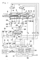
- reference numeral 1 designates a pneumatic cylinder as a hydraulic cylinder which includes a main body 2 having a tube 2a and a piston 3 slidably mounted in the tube 2a of the main body 2, wherein a hollow piston rod 4 fixed to the piston 3 accommodates therein a ball screw shaft which is rotatably and axially unmovably mounted in the main body 2 and is engaged with a ball nut 5 fixed to the piston 3 coaxially with the piston 3.
- Reference numeral 7 designates a magnetic brake which includes an armature 7a slidably and unrotatably mounted to the ball screw shaft 6 projecting from an end of the main body 2 and an electromagnet 7b which is fixed to the main body 2 and confronts the armature 7a.
- Reference numeral 8 designates a rotary encoder for detecting the number of revolutions of the ball screw shaft 6.
- a primary solenoid controlled valve 13 of a spring centered, 3-position, 5-port connection type connects a main line 10 connected to a first air source 9 either to a first line 11 communicated with a first port P1 of the pneumatic cylinder 1 or to a second line 12 communicated with a second port P2 thereof.
- a first braking line 15 connects a first braking pressure port P1′ provided on the tube 2a of the pneumatic cylinder 1 on the side opposite to the first port P1 to a second air source 14.
- a second braking line 16 connects a second braking pressure port P2′ provided on the tube 2a of the pneumatic cylinder 1 on the side opposite to the second port P2 to the second air source 14.
- Secondary solenoid controlled valves 17 and 18 of a normally closed, spring offset, 2-position, and 2-port connection type are provided on the first braking line 15 and the second braking line 16, respectively.
- a controller 19 outputs not only drive signals S3 and S3′ for controlling the primary solenoid controlled valve 13 but also primary braking signals S4 and S4′ and secondary braking signal S5 in accordance with operational sections (described later in detail) of the piston rod 4 as well as deviation between the signal S1 received from the rotary encoder 8 and a signal indicating a predetermined value, set by a signal input device (not shown) mounted on the controller 19, corresponding to a target position.
- the primary braking signals S4 and S4 are for switching on or off the second solenoid controlled valves 17 and 18 so that back pressure is applied to the piston 3 driven by air which flows through the primary solenoid controlled valve 13, and the secondary braking signal S5 for operating the magnetic brake 7.
- the controller can stop the piston rod 4 at desired positions by appropriately outputting the primary and secondary braking signals.
- Air pressure adjusting units 21, 21 are mounted alongside the first air source 9 of the main line 10 and the second air source 14, respectively.
- Each of the units 21, 21 has a pressure reducing valve 23 between an air pressure filter 22 and a lubricator 24.
- the first line 11 and second line 12 connected to the pneumatic cylinder 1 each are provided with a speed control valve 25 by a meter-out method.
- the speed control valve 25 includes a check valve 26 and a variable throttling valve 27 connected with each other in parallel.
- On the first line 11 are disposed a pressure reducing valve 28 and a check valve 29 for preventing air from flowing toward the first port P1 in parallel with each other between the speed control valve 25 and the primary solenoid controlled valve 13.
- the primary solenoid controlled valve 13 has a supply port S, cylindler ports C1 and C2, and exhaust ports E1 and E2.
- the supply port S communicates with the cylinder ports C1 and C2 when the primary solenoid controlled valve 13 is at a neutral position.
- Air is supplied to the first port P1 of the pneumatic cylinder 1 when the primary solenoid controlled valve 13 is at a offset position on the right-hand side of the drawing and to the second port P2 of the pneumatic cylinder 1 when it is at the other offset position on the left-hand side.
- Mufflers 30 are mounted at the exhaust port E1 and E2, respectively.
- the secondary solenoid controlled valve 18 When the primary solenoid controlled valve 13 takes the right offset position in response to the drive signal S3 transmitted from the controller 19, the secondary solenoid controlled valve 18 is switched to a offset position on the right-hand side of the drawing in response to the primary braking signal S4 transmitted from the controller 19 so as to supply back pressure to the second braking pressure port P2′.
- the secondary solenoid controlled valve 17 is switched to a offset position on the right-hand side in response to the primary braking signal S4′ so as to supply back pressure to the first braking pressure port P1′ when the primary solenoid controlled valve 13 is at the left offset position in response to the drive signal S3′.
- the controller 19 includes an interface 31 for reciprocating a signal S2 with an external device 20.
- the signal S2 indicates either how the pneumatic cylinder 1 is operated by the controller 19 or how it is remote-controlled by the external device 20.
- the controller 19 further includes a CPU 32 which controls the controller 19 and performs an operation necessary for controlling the pneumatic cylinder 1 in response to the signal S2 inputted through the interface 31 and the signal S1 inputted from the rotary encoder 8, respectively, a brake signal generation portion 33 which generates the secondary braking signal S5 to be provided to the magnetic brake 7 in response to the signal transmitted from the CPU 32, an exciting signal generation portion 34 which generates the drive signals S3 and S3′ to be supplied to the primary solenoid controlled valve 13 and the primary braking signals S4 and S4′ to be fed to the respective secondary solenoid controlled valves 17 and 18 in response to a signal transmitted from the CPU 32, and a driver 35 which amplifies and outputs the signals received from the signal generation portions 33 and 34.
- the CPU 32 When the CPU 32 receives a signal indicating the start of the positioning from a device equipped in the controller 19 or from the external unit 20, the CPU 32 divides the distance between a speed reduction starting position X1 and a target position X into (n) pieces of operation sections I1, ..., Ii, ..., I n and determines target piston speeds V1, ..., Vi, ..., V n for the respective operation sections in accordance with an ideal speed reduction curve C, as shown in fig. 2(a).
- a value set in advance by a target position setting device, namely, a keyboard (not shown) of the CPU 32, according to a positioning schedule and stored in the memory of the controller 19 is used as a target value corresponding to the target position.
- the CPU 32 has also intermittent operation means and continuous operation means which each are made of a program and function as follows:
- the intermittent operation means compares the target speed Vi of the operation section Ii with a measured piston speed V determined based on the signal S1 received from the rotary encoder 8. If V ⁇ Vi, the CPU 32 intermittently outputs the primary braking signals S4 or S4′ to the second solenoid controlled valve 17 or 18, and the secondary braking signal S5 to the magnetic brake 7. Accordingly, in Fig. 2(a), assuming that the ideal speed reduction curve C is identical with an actual piston speed V, there exists a region where V ⁇ Vi in every operation section, as shown in Fig. 2(a).
- intermittent brakes are applied to the piston rod 4 by the secondary solenoid controlled valve 17 or 18 and by the magnetic brake 7 in all the above operation sections.
- the level of the intermittent secondary braking force signal S5 changes at such a high speed, that, in average, the braking enabled by the signal S5 is considered to be continuously carried out.
- the continuous operation means when a measured piston speed exceeds the target speed in at least an operation section including the speed reduction start position X1 (in this case, only I1) on the (n) pieces of operation sections, the continuous operation means continues outputting the primary braking signals S4 or S4′ to the second solenoid controlled valve 17 or 18. As a result, the piston rod 4 is kept braked in all the region of the I1 irrespective of the measured piston speed V. Accordingly, if the measured piston speed V correspond to the ideal speed reduction curve C in Fig.
- Either only the intermittent operation means or both the intermittent operation means and the continuous operation means can be operated when a braking mode signal for selecting one out of the intermittent and continuous operation means is outputted from a setting device such as a switch mounted on the controller 19 or the external device 20.
- a setting device such as a switch mounted on the controller 19 or the external device 20.
- any combinations of operation sections in which the primary braking signals S4 or S4′ are intermittently outputted and operation sections in which the secondary braking signals S5 is intermittently outputted can be specified by a control mode signal for selecting the primary or secondary braking.
- any combinations of operation sections in which the primary braking signals S4 or S4′ are continuously outputted and operation sections in which the secondary braking signals S5 are intermittently outputted can be specified by the control mode signal. That is, the primary or secondary braking can be specified by the control mode signal in the respective speed regions. For example, referring to Fig.
- the primary braking can be selected for a high speed region and the secondary braking for middle and low speed regions and for the stop of the piston rod 4; or the primary braking for high and middle speed regions and the secondary braking for the middle and low speed regions and for the stop of the piston rod 4; or the primary braking in all the speed regions and the secondary braking only for the stop of the piston rod 4; and so on.
- either the intermittent or continuous operation means can be selected for the primary and secondary braking forces according to a braking mode signal.
- the continuous operation means may be selected for the primary braking force while the intermittent operation means may be selected for the secondary braking force.
- the intermittent operation means can be selected for both the primary and secondary braking forces.
- step S1 When a positioning start signal is inputted from a switch mounted on the external unit 20 or from the controller 19, the CPU 32 judges that the positioning control has started at step S1, and then, goes to step 2.
- the drive signal S3 is outputted to the primary solenoid controlled valve 13 through the exciting signal generation portion 34 and the driver 35 at step S2, the primary solenoid controlled valve 13 is switched to the right offset position.
- the primary air source 9 is connected to the first port P1 of the pneumatic cylinder 1 through the first line 11 and the second port P2 of the pneumatic cylinder 1 is opened to atmospheric air through the second line 12.
- step S3 the supply of the secondary braking signal S5 to the magnetic brake 7 through the brake signal generation portion 33 and the driver 35 is stopped.
- the armature 7a attracted to the electromagnet 7b moves apart from it and the ball screw shaft 6 becomes rotatable. Accordingly, the piston 3 is moved toward the left in Fig. 1 by the air supplied from the first port P1 and this forward stroke of the piston 3 is converted into the rotation of the ball screw shaft 6 through the ball nut 5 fixed to the piston 3.
- the rotary encoder 8 detects the number of revolutions of the ball screw shaft 6 and provides the CPU 32 of the controller 19 with the pulse signal S1 corresponding to the position of the piston 3 determined based on the detected number of revolutions.
- the CPU 32 determines the speed reduction start position X1 in accordance with the ideal speed reduction curve C (See Fig. 2) and divides the curve C into (n) pieces of operation sections, and determines according to the braking mode signal and the control mode signal whether the brakings of the respective operation sections are of the intermittent or continuous mode and whether the brakings of the respective operation sections are of a first braking mode where the secondary solenoid controlled valve 17 or 18 operates or of a second braking mode where the magnetic brake 7 operates or of a combined braking mode where the secondary valve 17 or 18 and the magnetic brake operate in combination.
- the control and braking modes are set as shown in Fig. 2(c), the description of the flow charts is made hereinafter.
- step S4 the CPU 32 discriminates whether or not the piston position indicated by the pulse signal S1 from the rotary encoder 8 has reached the speed reduction start position X1. If the result of the discrimination indicates YES, the program goes to step S5 at which "first braking subroutine" is carried out for the brakes at the first operational section.
- the first braking subroutine is carried out as shown in Fig. 4. That is, at step S31, the CPU 32 discriminates whether or not the piston position indicated by the pulse signal S1 is in a primary braking mode section. If the result of the discrimination indicates NO, the primary braking force is cancelled at step S34, and then, the program returns. If the result of the discrimination at step S31 indicates YES, it is discriminated at step S32 whether the continuous operation means or the intermittent operation means is selected under the braking mode. If the continuous operation means is selected, the primary braking force is applied continuously at step S36. Thereafter, the program returns.
- step S33 If the intermittent operation means is selected under the braking mode, it is decided at step S33 whether or not the measured piston speed V indicated by the pulse signal S1 is equal to or higher than the speed V i of the operation section Ii. If the result of the decision indicates YES, that is, V ⁇ Vi, the program goes to step S35, at which the controller 19 intermittently outputs the primary braking signal S4 to the secondary solenoid controlled valve 18, whereby the secondary solenoid controlled valve 18 is switched to the right offset position so as to connect the second air source 14 to the second braking pressure port P2′ of the pneumatic cylinder 1 through the second braking line 16. As a result, back pressure is applied from the second braking pressure port P2′ to the piston 3 which is moving toward the left in Fig.
- step S6 "secondary braking subroutine" is carried out for the second operation section I2 and the following operation sections shown in Fig. 2(c). It is judged at step S40 whether or not the piston position indicated by the pulse signals S1 is in the secondary braking section where the secondary braking force is applied by the magnetic brake 7. If the result of the judgement indicates NO, the secondary braking force is cancelled at step S43, and the program returns. If the piston position is in the secondary braking section. It is discriminated at step S41 whether the continuous operation means or the intermittent operation means is selected under the braking mode. If the continuous operation means is selected, the secondary braking force is applied at step S45, and then, the program returns.
- the intermittent operation means it is discriminated whether or not the measured piston speed V is equal to and higher than the target speed Vi (i ⁇ 2) of the respective sections Ii. If the result of the discrimination indicates YES, namely, V ⁇ Vi, the program goes to step S44 so that an intermittent braking is applied. If the discrimination result indicates V ⁇ Vi, the program goes to step S43 so as to cancel the intermittent braking, and then, returns.
- step S9 it is decided whether or not the piston position indicated by the pulse signals S1 corresponds to a final operation section. If the piston position is not in the final operational section, the program returns to step S4, and repeats the braking loop consisting of steps S4, S5, S6 and S9. If the piston position is in the final section, the program goes to step S10 at which it is discriminated whether or not the piston rod 4 has reached the target position X. If the discrimination result indicates YES, the secondlary braking signal S5 is outputted from the controller 19 to the magnetic brake 7 and the magnetic brake 7 brakes the rotation of the ball screw shaft 6 so as to stop the piston rod 4. Next, it is decided whether or not the piston rod 4 has stopped at the target position X.
- step S2 the program returns to step S2 at which a fine adjustment of the stop position is made. If the discrimination indicates that the piston rod 4 has stopped at the target position X, the program goes to step S13 at which the controller 19 stops outputting the drive signal S3 to the primary solenoid controlled valve 13. As a result, the primary solenoid controlled valve 13 takes the neutral position. The positioning of the piston rod 4 is effected with air pressure applied from the first air source 9 to both sides of the piston 3. Finally, at step S14, a signal indicative of the positioning completion is outputted to the external unit 20. At step S15, the next target position is set by the CPU 32 in accordance with the positioning schedule, and then, the program returns to step S1. In addition, when the piston rod 4 is moved backward, that is, toward the right in Fig. 1, the positioning control of the piston rod 4 is effected in the same manner as described above.
- air is introduced from the air source 14 into the first and secondary braking pressure ports P1′ and P2′ formed at both end portions of the tube 2a of the pneumatic cylinder 1 through the first and second braking lines 15 and 16 used only for braking. Therefore, back pressure is effectively applied to the piston 3 and the primary braking is effectively accomplished compared with the case in which air of the air source 9 would be introduced into the tube 2a through the lines 11 and 12 which have many elements, and the first and second ports P1 and P2 for braking the piston rod 4.
- the CPU 32 of the controller 19 sets the control modes of the respective operation sections Ii according to the ideal speed reduction curve C.
- the second solenoid controlled valves 17 and 18 acting as the primary braking means and the magnetic brake 7 acting as the secondary braking means are operated in any desired combination by appropriately selecting the intermittent operation means and the continuous operation means so that they are operated independently or in combination. Therefore, the piston rod 4 is optimally braked depending on operation sections, so that vibration and shock generated in a braking operation is relieved to a great extent compared with the continuous braking effected by a conventional magnetic brake. Furthermore, the piston rod is stopped at a predetermined position and the positioning of the piston rod is accurately carried out. In addition, the magnetic brake is much more durable than the conventional one, because the magnetic brake is used with the back pressure brake.
- the controller 19 is provided with means for detecting the following errors; errors in controlling the piston such as, for example, non-operation of the piston 3, non-stop of the piston 3 at a target position and an excess over the allowable speed of the piston; errors in the system such as an unexpected instruction to start speed reduction, made without data input of a target position, abnormality in the memory data on a target position due to noise or the like, and non-preferable back-up of the memory.
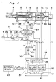
- the fluid apparatus shown in Fig. 6 is a modification of the one described above in which the second air source 14, the first and second braking lines 15 and 16, and the second solenoid controlled valves 17 and 18, which form the primary braking means, are omitted from the one shown in Fig. 1 and an exhaust throttle valve 101 is mounted on the exhaust side of the pneumatic cylinder 1 so that it acts as the primary braking means. That is, the speed control valves 25 provided on the first line 11 and the second line 12, respectively, as shwon in Fig. 1, are not provided and the exhaust ports E1 and E2 of the primary solenoid controlled valve 13 are connected to a 2-position and 3-port connection solenoid controlled valve 100 which is switched by a primary braking signal S6 outputted from the controller 19.
- the throttle valve 101 is provided on one of the exhaust lines of the valve 100 so that exhaust gas from the pneumatic cylindler 1 is discharged through the throttle valve 101.
- back pressure is applied to the piston 3 to brake the piston 3.
- an electro-dynamic brake 36 (See Fig. 1) whose braking force is adjusted by the primary braking signal transmitted from the controller 19 is mounted on the end 6a of the ball screw shaft 6 of the pneumatic cylinder 1 so as to apply the primary braking force to the piston rod 4.
- first and second braking lines may be connected to the first and second ports P1 and P2, respectively.
- Fig. 7 shows an example of such a case. The construction of this example is the same as that shown in Fig. 1.
- a first braking line 15′ is connected to the first line 11 communicated to the first port P1 and a second braking line 16′ is connected to the second line 12 communicated to the second port P2.
- a single 2-position and 3-port connection directional control valve may be provided at the position at which the first and second braking lines are confluent, instead of the secondary solenoid controlled valve.
- the braking mode in accorldance with the present invention is not limited to the one in the embodiments.
- an optimum control for the braking of the piston rod is accomplished for every operation section by the continuous or intermittent application of the primary braking effected by the second solenoid controlled valve in appropriate combination with the secondary braking effected by the magnetic brake. Therefore, vibration and shock which will occur during a braking operation is relieved to a great extend compared with the conventional continuous braking effected by a magnetic brake only. In this way, the piston can be stopped and positioned at a desired position very accurately.
- the magnetic brake can be very durable.
Landscapes
- Engineering & Computer Science (AREA)
- Physics & Mathematics (AREA)
- Fluid Mechanics (AREA)
- Mechanical Engineering (AREA)
- General Engineering & Computer Science (AREA)
- Human Computer Interaction (AREA)
- Manufacturing & Machinery (AREA)
- General Physics & Mathematics (AREA)
- Automation & Control Theory (AREA)
- Actuator (AREA)
- Fluid-Pressure Circuits (AREA)
- Braking Arrangements (AREA)
Applications Claiming Priority (2)
| Application Number | Priority Date | Filing Date | Title |
|---|---|---|---|
| JP334045/87 | 1987-12-29 | ||
| JP33404587 | 1987-12-29 |
Publications (2)
| Publication Number | Publication Date |
|---|---|
| EP0322503A2 true EP0322503A2 (de) | 1989-07-05 |
| EP0322503A3 EP0322503A3 (de) | 1991-09-25 |
Family
ID=18272892
Family Applications (1)
| Application Number | Title | Priority Date | Filing Date |
|---|---|---|---|
| EP19880112065 Withdrawn EP0322503A3 (de) | 1987-12-29 | 1988-07-26 | Flüssigkeitsgerät |
Country Status (3)
| Country | Link |
|---|---|
| US (1) | US4932311A (de) |
| EP (1) | EP0322503A3 (de) |
| KR (1) | KR920007656B1 (de) |
Cited By (11)
| Publication number | Priority date | Publication date | Assignee | Title |
|---|---|---|---|---|
| WO2000053937A1 (en) * | 1999-03-08 | 2000-09-14 | Lord Corporation | Linear-acting controllable pneumatic actuator and motion control apparatus including a field responsive medium and control method therefor |
| WO2000053936A1 (en) * | 1999-03-08 | 2000-09-14 | Lord Corporation | Controllable pneumatic apparatus including a rotary-acting brake with field responsive medium and control method therefor |
| EP1106841A3 (de) * | 1999-12-07 | 2003-09-24 | Weber-Hydraulik GmbH | Linearverstellantrieb |
| EP1420171A3 (de) * | 2002-10-22 | 2004-05-26 | Bümach Engineering International B.V. | Hydraulischer Arbeitszylinder |
| WO2005017366A1 (de) * | 2003-08-19 | 2005-02-24 | Supraventures Ag | Fluidzylinder |
| EP1538343A3 (de) * | 2003-12-04 | 2005-08-10 | Neumeister Hydraulik GmbH | Verriegelungszylinder |
| CN101737365B (zh) * | 2009-12-17 | 2012-11-28 | 中联重科股份有限公司 | 流动式起重机、转向中位定位锁定装置及其中位油缸 |
| CN104819182A (zh) * | 2015-04-02 | 2015-08-05 | 青岛理工大学 | 一种可实现精确定位的无杆气缸 |
| WO2017076965A1 (de) * | 2015-11-06 | 2017-05-11 | Pleiger Maschinenbau Gmbh & Co. Kg | Verfahren und vorrichtung zum ansteuern einer hydraulisch betätigten antriebseinheit einer armatur |
| WO2017099616A1 (en) * | 2015-12-08 | 2017-06-15 | Politechnika Wrocławska | Method of filling and emptying the working chamber of the hydraulic cylinder and a hydraulic cylinder together with a control system and a hydraulic cylinder for performing the method according to the invention |
| EP3490777B1 (de) | 2016-07-28 | 2020-04-22 | Runipsys Europe | System zur steuerung einer blende eines kunststoffeinspritzsystems |
Families Citing this family (50)
| Publication number | Priority date | Publication date | Assignee | Title |
|---|---|---|---|---|
| CH678968A5 (de) * | 1989-09-28 | 1991-11-29 | Asea Brown Boveri | |
| DE4001938C3 (de) * | 1990-01-24 | 2001-07-19 | Mannesmann Ag | Lineareinheit |
| EP0575343B1 (de) * | 1991-01-14 | 1995-05-03 | Engel Maschinenbau Gesellschaft m.b.H. | Vorrichtung zur durchführung einer zweistufigen linearen bewegung |
| US5147117A (en) * | 1991-03-19 | 1992-09-15 | General Motors Corporation | Integrated anti-lock braking and traction control system |
| US5983149A (en) * | 1991-04-08 | 1999-11-09 | Caterpillar Inc. | Automatic vehicle speed retarding control through actuation of wheel brakes |
| US5424941A (en) * | 1991-08-02 | 1995-06-13 | Mosier Industries, Inc. | Apparatus and method for positioning a pneumatic actuator |
| US5154207A (en) * | 1991-08-02 | 1992-10-13 | Mosier Industries, Inc. | Pressure control valve and transducer package |
| JPH05209601A (ja) * | 1992-01-31 | 1993-08-20 | Canon Inc | シリンダ装置及びその制御方法 |
| US5301708A (en) * | 1993-02-09 | 1994-04-12 | Aluminum Company Of America | Rotary plug valve actuator and associated rotary plug valve and associated method |
| IT1271509B (it) * | 1993-10-06 | 1997-05-30 | Luciano Migliori | Attuatore pneumatico lineare con freno ad azione reversibile |
| US5540048A (en) * | 1995-01-30 | 1996-07-30 | Martin Marietta Corporation | Continuously variable hydrostatic transmission including a pulse width modulation ratio controller |
| JP3626234B2 (ja) * | 1995-02-06 | 2005-03-02 | Smc株式会社 | シリンダ位置決め制御方法 |
| US5542336A (en) * | 1995-04-17 | 1996-08-06 | Martin Marietta Corporation | Positioning apparatus and method utilizing PWM control of a double-acting hydraulic cylinder |
| DE69527093D1 (de) * | 1995-10-02 | 2002-07-18 | Pos Line Ab | Verfahren und ventilvorrichtung zum steuern eines hin-und herbewegenden hydraulischen antriebs |
| JP4186135B2 (ja) * | 1998-05-15 | 2008-11-26 | Smc株式会社 | シリンダ用速度制御装置 |
| US6003428A (en) * | 1998-07-24 | 1999-12-21 | Smc Pneumatics, Inc. | Electro-pneumatic pressure control system for welding and like apparatus |
| SE521326C2 (sv) * | 1998-09-04 | 2003-10-21 | Delaval Holding Ab | En skyddsanordning för kontroll av rörelsen hos ett pneumatiskt manövreringsorgan |
| EP1234118A4 (de) | 1999-10-27 | 2003-08-13 | Tol O Matic Inc | Präzisionsregelungssystem eines pneumatischen stellglieds |
| US6352018B1 (en) * | 2000-04-20 | 2002-03-05 | Spicer Technology, Inc. | Hydraulic actuator assembly with integral damper/accumulator |
| US7040349B2 (en) * | 2002-03-27 | 2006-05-09 | Viking Technologies, L.C. | Piezo-electric actuated multi-valve manifold |
| JP2004100759A (ja) * | 2002-09-06 | 2004-04-02 | Komatsu Ltd | スイング式油圧ショベルのスイング制御装置 |
| US7021191B2 (en) * | 2003-01-24 | 2006-04-04 | Viking Technologies, L.C. | Accurate fluid operated cylinder positioning system |
| CA2521307C (en) | 2003-04-04 | 2014-07-15 | Viking Technologies, L.C. | Apparratus and process for optimizing work from a smart material actuator product |
| JP4206887B2 (ja) * | 2003-09-30 | 2009-01-14 | 株式会社日立製作所 | マスタシリンダ装置 |
| US7320198B2 (en) * | 2004-08-24 | 2008-01-22 | Hi-Lex Controls, Inc. | Integrated gas spring actuator strut assembly with threaded nut in gas spring |
| JP4353333B2 (ja) * | 2007-03-30 | 2009-10-28 | Smc株式会社 | 複動形エアシリンダの位置決め制御機構 |
| CN201043548Y (zh) * | 2007-04-23 | 2008-04-02 | 吴文胜 | 油电混合油缸 |
| DE102008045564A1 (de) * | 2008-09-03 | 2010-03-04 | Daimler Ag | Antriebseinrichtung für eine Tür und Verfahren zum Betreiben einer Antriebseinrichtung |
| DE102010038448B3 (de) * | 2010-07-27 | 2011-11-03 | Voith Patent Gmbh | Verfahren zum Betreiben einer hydraulischen Antriebsvorrichtung und hydraulische Antriebsvorrichtung |
| US8753564B2 (en) * | 2011-06-13 | 2014-06-17 | Mac Valves, Inc. | Piston rod and cylinder seal device for aluminum bath crust breaker |
| RU2529988C1 (ru) * | 2013-02-13 | 2014-10-10 | Открытое акционерное общество "Ракетно-космическая корпорация "Энергия" имени С.П. Королева" | Пневмопривод с тормозным устройством |
| KR101361235B1 (ko) * | 2013-07-16 | 2014-02-11 | 임성일 | 이중 구조의 공압실린더 및 이를 포함하는 기계장치 |
| JP6230873B2 (ja) * | 2013-10-24 | 2017-11-15 | ナブテスコ株式会社 | 電動アクチュエータ及びアクチュエータユニット |
| CN106194894B (zh) * | 2016-08-31 | 2018-11-30 | 润邦卡哥特科工业有限公司 | 一种液压油缸缓冲装置 |
| CN107449479B (zh) * | 2017-07-26 | 2020-10-02 | 南通通力油泵有限公司 | 一种非接触式气动计量柱塞泵 |
| CN108098826A (zh) * | 2017-12-13 | 2018-06-01 | 同济大学 | 一种大型工业机器人液压伺服关节 |
| US10793261B2 (en) | 2018-04-13 | 2020-10-06 | The Boeing Company | Electro-mechanically biased supercritical flight control surface loading to reduce high pressure actuation cycles |
| US10711809B2 (en) | 2018-04-13 | 2020-07-14 | The Boeing Company | Aircraft hydraulic system with a dual spool valve and methods of use |
| US10947997B2 (en) | 2018-04-13 | 2021-03-16 | The Boeing Company | Aircraft hydraulic system with a dual spool valve and methods of use |
| US10526071B2 (en) * | 2018-04-13 | 2020-01-07 | The Boeing Company | Hydraulic systems and methods to control a member |
| US10723441B2 (en) | 2018-04-13 | 2020-07-28 | The Boeing Company | High-speed-deployed, drum-brake, inertia disk for rack and pinion rotational inerter |
| US10737764B2 (en) | 2018-04-13 | 2020-08-11 | The Boeing Company | Base flight control member orientation mechanism and control |
| US11072418B2 (en) | 2018-04-13 | 2021-07-27 | The Boeing Company | Hydraulic system for an aircraft |
| DE102019120863A1 (de) * | 2019-08-01 | 2021-02-04 | Atlas Copco Ias Gmbh | Verfahren zur Steuerung eines mechanischen Füge- oder Umformprozesses |
| US11187023B2 (en) * | 2019-12-27 | 2021-11-30 | Hamilton Sundstrand Corporation | Piston assembly for aircraft door |
| US11092175B1 (en) * | 2020-03-23 | 2021-08-17 | The Boeing Company | Dual-independent hybrid actuator system |
| DE102020209578A1 (de) * | 2020-07-29 | 2022-02-03 | Hawe Hydraulik Se | Zylindereinrichtung für eine hydraulische hubvorrichtung mit wegmessung, hydraulische hubvorrichtung, fahrgestell sowie mobile vorrichtung |
| CN112460095B (zh) * | 2020-11-30 | 2021-11-19 | 北京理工大学 | 一种电液复合缸的主被动负载复合控制方法 |
| US12449216B2 (en) | 2023-06-16 | 2025-10-21 | Textron Systems Corporation | Fluid power actuator utilizing a screw assembly |
| US12313095B2 (en) * | 2023-08-17 | 2025-05-27 | Textron Systems Corporation | Fluid power actuator utilizing a screw and nut assembly |
Family Cites Families (12)
| Publication number | Priority date | Publication date | Assignee | Title |
|---|---|---|---|---|
| US2936737A (en) * | 1955-07-25 | 1960-05-17 | Miller J Carter | Rotary actuator |
| US3807810A (en) * | 1971-07-07 | 1974-04-30 | Yarber A | Brake control valve system |
| DE2327387C3 (de) * | 1973-05-29 | 1978-10-12 | Pfaff Pietzsch Industrieroboter Gmbh, 7505 Ettlingen | Antrieb für Handhabungseinrichtungen |
| JPS6014201B2 (ja) * | 1975-12-01 | 1985-04-12 | 黒田精工株式会社 | 空圧デイジタルシリンダー装置 |
| US4075930A (en) * | 1976-04-28 | 1978-02-28 | The Garrett Corporation | Pneumatic actuator system and method |
| US4235156A (en) * | 1978-11-16 | 1980-11-25 | Zenny Olsen | Digital servovalve and method of operation |
| DE3219730A1 (de) * | 1982-05-26 | 1983-12-01 | Robert Bosch Gmbh, 7000 Stuttgart | Einrichtung zur steuerung eines hydraulischen servomotors |
| DE3313623C2 (de) * | 1983-04-12 | 1985-02-07 | Kracht Pumpen- Und Motorenfabrik Gmbh & Co Kg, 5980 Werdohl | Steuerung für hydraulische Antriebe |
| US4545289A (en) * | 1983-09-09 | 1985-10-08 | Weyer Paul P | Adjustable rotary actuator |
| JPS60263713A (ja) * | 1984-06-11 | 1985-12-27 | Takashi Kimura | 減速装置付中間停止空気圧シリンダ |
| US4617637A (en) * | 1985-07-09 | 1986-10-14 | Lifecare Services, Inc. | Servo control system for a reciprocating piston respirator |
| DE3530286A1 (de) * | 1985-08-24 | 1987-03-05 | Kugelfischer G Schaefer & Co | Druckmodulator |
-
1988
- 1988-07-26 EP EP19880112065 patent/EP0322503A3/de not_active Withdrawn
- 1988-08-05 US US07/229,062 patent/US4932311A/en not_active Expired - Fee Related
- 1988-09-29 KR KR1019880012598A patent/KR920007656B1/ko not_active Expired
Cited By (14)
| Publication number | Priority date | Publication date | Assignee | Title |
|---|---|---|---|---|
| WO2000053937A1 (en) * | 1999-03-08 | 2000-09-14 | Lord Corporation | Linear-acting controllable pneumatic actuator and motion control apparatus including a field responsive medium and control method therefor |
| WO2000053936A1 (en) * | 1999-03-08 | 2000-09-14 | Lord Corporation | Controllable pneumatic apparatus including a rotary-acting brake with field responsive medium and control method therefor |
| US6302249B1 (en) | 1999-03-08 | 2001-10-16 | Lord Corporation | Linear-acting controllable pneumatic actuator and motion control apparatus including a field responsive medium and control method therefor |
| EP1106841A3 (de) * | 1999-12-07 | 2003-09-24 | Weber-Hydraulik GmbH | Linearverstellantrieb |
| EP1420171A3 (de) * | 2002-10-22 | 2004-05-26 | Bümach Engineering International B.V. | Hydraulischer Arbeitszylinder |
| WO2005017366A1 (de) * | 2003-08-19 | 2005-02-24 | Supraventures Ag | Fluidzylinder |
| EP1538343A3 (de) * | 2003-12-04 | 2005-08-10 | Neumeister Hydraulik GmbH | Verriegelungszylinder |
| CN101737365B (zh) * | 2009-12-17 | 2012-11-28 | 中联重科股份有限公司 | 流动式起重机、转向中位定位锁定装置及其中位油缸 |
| CN104819182A (zh) * | 2015-04-02 | 2015-08-05 | 青岛理工大学 | 一种可实现精确定位的无杆气缸 |
| WO2017076965A1 (de) * | 2015-11-06 | 2017-05-11 | Pleiger Maschinenbau Gmbh & Co. Kg | Verfahren und vorrichtung zum ansteuern einer hydraulisch betätigten antriebseinheit einer armatur |
| US10731675B2 (en) | 2015-11-06 | 2020-08-04 | Pleiger Maschinenbau Gmbh & Co. Kg | Method and device for controlling a hydraulically actuated drive unit of a valve |
| WO2017099616A1 (en) * | 2015-12-08 | 2017-06-15 | Politechnika Wrocławska | Method of filling and emptying the working chamber of the hydraulic cylinder and a hydraulic cylinder together with a control system and a hydraulic cylinder for performing the method according to the invention |
| EP3490777B1 (de) | 2016-07-28 | 2020-04-22 | Runipsys Europe | System zur steuerung einer blende eines kunststoffeinspritzsystems |
| US11027471B2 (en) | 2016-07-28 | 2021-06-08 | Runipsys Europe | System for controlling a shutter of a plastics injection system |
Also Published As
| Publication number | Publication date |
|---|---|
| US4932311A (en) | 1990-06-12 |
| EP0322503A3 (de) | 1991-09-25 |
| KR890010432A (ko) | 1989-08-08 |
| KR920007656B1 (ko) | 1992-09-14 |
Similar Documents
| Publication | Publication Date | Title |
|---|---|---|
| EP0322503A2 (de) | Flüssigkeitsgerät | |
| EP0397328B1 (de) | Fahrzeug-Antriebssteuervorrichtung und -verfahren | |
| KR100432381B1 (ko) | 전기-유압식비례제어밸브조립체 | |
| EP0292473B1 (de) | VERFAHREN ZUR REDUZIERUNG DER KOLBENGESCHWINDIGKEIT, INSBESONDERE FüR KOLBEN-UND ZYLINDERANORDNUNGEN VON ERDBEWEGUNGSMASCHINEN UND VORRICHTUNG ZUR DURCHFüHRUNG DES VERFAHRENS | |
| CA1242781A (en) | Power transmission | |
| CA1259885A (en) | Power drive unit and control system therefor | |
| EP0397330B1 (de) | Fahrzeug-Antriebssteuervorrichtungsverfahren | |
| EP0703118B1 (de) | Kraftfahrzeug-Bremskraftsteuergerät | |
| EP0448145A2 (de) | Methode zur Regelung der Geschwindigkeit eines Motors | |
| EP0538920A1 (de) | Integriertes Antiblockierbrems- und Traktionsregelsystem | |
| CN110789505B (zh) | 避免在能电子滑动调节的制动设备的压力介质回路中压力过高的方法和相应的制动设备 | |
| KR19990014702A (ko) | 연속가변 전동장치를 위한 제어밸브를 갖는 유압식 비상제어장치 | |
| KR20200003476A (ko) | Esc 통합형 제동 시스템의 abs 제어 장치 및 방법 | |
| US5907952A (en) | Capacity control device for a hydraulic motor for a hydraulically driven vehicle | |
| JP2831093B2 (ja) | 電気油圧式システム | |
| US4689955A (en) | Vibration roller having a power limiting device | |
| US3536361A (en) | Blending scheme for current responsive railway brake | |
| JPH0995222A (ja) | 減速付加装置 | |
| EP0822917B1 (de) | Aufzugssteuerungssystem | |
| US5606901A (en) | Hydraulic circuit for turning purposes | |
| EP0415133B1 (de) | Hydraulische Schaltungen für Verbraucher | |
| US5079989A (en) | Electrohydraulic valve system with a pressure feedback signal modulated by a velocity feedback signal when the velocity exceeds a veloity limit | |
| SU1049300A2 (ru) | Система автоматического управлени торможением | |
| RU2750559C1 (ru) | Система и способ управления пневматическим приводом вагонного замедлителя | |
| CA2041766A1 (en) | Pulse width modulated pressure control valve configuration |
Legal Events
| Date | Code | Title | Description |
|---|---|---|---|
| PUAI | Public reference made under article 153(3) epc to a published international application that has entered the european phase |
Free format text: ORIGINAL CODE: 0009012 |
|
| 17P | Request for examination filed |
Effective date: 19880822 |
|
| AK | Designated contracting states |
Kind code of ref document: A2 Designated state(s): DE FR GB |
|
| PUAL | Search report despatched |
Free format text: ORIGINAL CODE: 0009013 |
|
| AK | Designated contracting states |
Kind code of ref document: A3 Designated state(s): DE FR GB |
|
| 17Q | First examination report despatched |
Effective date: 19921210 |
|
| STAA | Information on the status of an ep patent application or granted ep patent |
Free format text: STATUS: THE APPLICATION HAS BEEN WITHDRAWN |
|
| 18W | Application withdrawn |
Withdrawal date: 19940513 |