EP0322516A2 - Centrifuge à bol plein - Google Patents
Centrifuge à bol plein Download PDFInfo
- Publication number
- EP0322516A2 EP0322516A2 EP88115690A EP88115690A EP0322516A2 EP 0322516 A2 EP0322516 A2 EP 0322516A2 EP 88115690 A EP88115690 A EP 88115690A EP 88115690 A EP88115690 A EP 88115690A EP 0322516 A2 EP0322516 A2 EP 0322516A2
- Authority
- EP
- European Patent Office
- Prior art keywords
- drum
- discharge
- centrifuge
- compressed air
- centrifuge according
- Prior art date
- Legal status (The legal status is an assumption and is not a legal conclusion. Google has not performed a legal analysis and makes no representation as to the accuracy of the status listed.)
- Withdrawn
Links
Images
Classifications
-
- B—PERFORMING OPERATIONS; TRANSPORTING
- B04—CENTRIFUGAL APPARATUS OR MACHINES FOR CARRYING-OUT PHYSICAL OR CHEMICAL PROCESSES
- B04B—CENTRIFUGES
- B04B1/00—Centrifuges with rotary bowls provided with solid jackets for separating predominantly liquid mixtures with or without solid particles
- B04B1/20—Centrifuges with rotary bowls provided with solid jackets for separating predominantly liquid mixtures with or without solid particles discharging solid particles from the bowl by a conveying screw coaxial with the bowl axis and rotating relatively to the bowl
- B04B2001/2083—Configuration of liquid outlets
-
- B—PERFORMING OPERATIONS; TRANSPORTING
- B04—CENTRIFUGAL APPARATUS OR MACHINES FOR CARRYING-OUT PHYSICAL OR CHEMICAL PROCESSES
- B04B—CENTRIFUGES
- B04B1/00—Centrifuges with rotary bowls provided with solid jackets for separating predominantly liquid mixtures with or without solid particles
- B04B1/20—Centrifuges with rotary bowls provided with solid jackets for separating predominantly liquid mixtures with or without solid particles discharging solid particles from the bowl by a conveying screw coaxial with the bowl axis and rotating relatively to the bowl
- B04B2001/2091—Configuration of solids outlets
Definitions
- the invention relates to a full-fledged centrifuge, in particular for separating media of different densities or their mixtures and / or suspensions that are difficult to separate into a comparatively lighter and at least one heavier phase, with a drum rotatably mounted on a shaft and a cylindrical clarifying pond in itself and with Organs for entering the media to be separated and for discharging the separated phases.
- centrifuges of this type for. B. from DE-OS 33 17 047 known, in which along the clarification pond at a distance from the inner wall of the drum a rotatably mounted with a hollow shaft and extending in the direction of the axis of rotation arranged displacement body, and the centrifuge is designed with means for operation in direct current , wherein the entry element for the medium to be separated is arranged at the inflow area of the clarification pond and the discharge elements for the separate phases are arranged starting from the discharge area.
- German utility model 84 60 004.7 proposes an overflow separation centrifuge for the separation treatment of sludge with a liquid discharge tube protruding into the drum and having a sleeve at the free end, the sleeve being adjustable to skim off a phase at different depths in the sedimentation pond.
- Such a device is very difficult to operate and also prone to failure.
- Another known centrifuge according to DE-OS 26 51 657 has a clear liquid overflow at a point between the inlet and the solids discharge, the overflow member consisting of a plurality of tubes projecting radially from the outside into the clarification chamber.
- the accumulation height can be adjusted by letting the tubes protrude more or less far into the clarification room.
- a solid-bowl screw centrifuge of cylindrical design for separating suspensions which are difficult to separate which has a separating disc at the end of the separating space and clear-phase channels arranged in front of the separating disc and sediment channels behind the separating disc. Both discharges lead out of the centrifuge drum in the area of the center thereof.
- a measuring cell for determining the dry matter content is arranged in the sediment discharge and controls a quantity control element in the clear phase discharge line in accordance with the constant solids content in the sediment.
- the known device requires a supply of the suspension with pressure between 0.4 to 0.6 MPa and thus a sealing of the bearings.
- the object of the invention is to provide a centrifuge of the type mentioned, in which the phases separation difficult to separate z.
- B. sewage sludge largely avoiding energy losses and without a complicated design of the centrifuge as well as avoiding overpressure operation and with a simple control of the solids content in phases containing different solids, and which can be created with as little effort as possible in manufacturing, assembly and maintenance costs and with economic energy expenditure is operable.
- the suspension to be separated is guided precisely with regard to maximum selectivity.
- the arrangement of the displacement body ensures that a large surface of the clarification pond corresponding to the diameter of the displacement body is retained in the sedimentation area, whereas the entry and the discharge area of the media is comparatively closely associated with the center of rotation. This saves drive energy and ensures energy-efficient operation.
- the conveying device is designed as a compressed air liquid lifter based on the principle of the so-called mammoth pump and is connected to a compressed air line which is guided through the hollow shaft into the interior of the drum.
- the compressed air liquid lifter advantageously has a very simple embodiment, requires no moving parts, is uncomplicated, effective in terms of the conveying effect and, in particular, controllable within predetermined limits with regard to the conveying capacity.
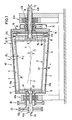
- FIG. 1 shows the solid bowl centrifuge (40) with a drum (2) mounted on hollow shafts (41a, 41b) on both sides in the bearing blocks (42a, 42b). Inside the drum (2) there is a hollow displacement body (6) immersed in the clarification pond (3). This is also rotatably supported on both sides on the hollow shafts (43a) and (43b) in the bearing blocks (42a) and (42b).
- the centrifuge (40) suspension indicated by the arrow (44), is fed through the hollow shaft (43a).
- the suspension (44) exits through the openings (45) in the hollow shaft (43) and enters the interior of the drum (2) and forms the clarification pond (3) there during operation.
- the hollow shaft (41a) of the drum (2) has a V-belt pulley (26) for driving and the hollow shaft (43a) of the displacement body has a V-belt pulley (25). 2, in cooperation with the V-belt sweater (27) of the drive motor (28), form a differential V-belt drive (24) for the centrifuge (40).
- the jacket (1) of the drum (2) is preferably formed with a conical extension (4) in the flow direction of the clarifying pond (3).
- the suspension entering the artificial gravity field through the openings (45) on the left-hand side according to FIG. 1 becomes an acceleration component for the content particles of the heavier phase in the flow direction (10) granted.
- the particles obviously have the tendency to migrate to the right in the clarification pond (3) to the area of the largest drum diameter and thereby sediment.
- the centrifuge (40) works in direct current while maintaining optimal separation sharpness conditions, the displacement body (6), designed as a smooth truncated cone, not causing disturbing eddies or a counterflow field at any point in the clarifying pond (3).
- the discharge element (8) for the light phase (14) leads to an overflow (8a) on the drum end wall (16) and the discharge element (9) for the heavier phase (13) from the deepest area ( 17) of the clarification pond (3), starting with a conveying device (18), and arranged to open into the hollow shaft (43b).
- This conveying device (18) is designed as a compressed air liquid lifter (37a, 37b) and connected to a compressed air line (19) which is guided through the hollow shaft (43b) into the interior of the drum (2).
- the arrangement is surprisingly simple, at the same time functionally reliable and energetically economical.
- the conical widening (4) of the jacket (1) of the drum (2) with an opening angle ( ⁇ 1) between 1 ° and 8 °, preferably between 3 ° and 5 ° and the ver is advantageous thrust body (6) with a rotationally symmetrical jacket (20) in the form of a truncated cone with an opening angle ( ⁇ 2) which essentially corresponds to the opening angle ( ⁇ 1) of the drum shell (1).
- An expedient embodiment of the centrifuge further provides that the displacement body (6) has clearing elements (21).
- Such batches are preferably formed during the dewatering of viscous, pasty sludge, in particular sewage treatment plant sludge.
- the clearing elements (21) are two clearing strips standing vertically opposite one another on the jacket (20) in the embodiment shown as an example. Through this the accumulation of the solid-liquid mixture Solids in the area of the inner drum wall (5) kept in motion so that they cannot get stuck.
- Each broach (21a, 21b) can be designed as a helix with a very large pitch with a pitch angle ( ⁇ ) with respect to the axis of rotation (x-x) of the system between 0 and 10 °, preferably between 3 and 5 °. This measure supports and evenens the transport of the solids in the centrifuge drum (2) to the solids discharge end (15).
- the small difference in rotational speed between the displacement body (6) with clearing elements (21a, 21b) compared to the drum (2), in contrast to the transport of solids by means of a helix, requires only a negligibly small amount of drive energy.
- this drive can be designed very simply, preferably as a V-belt drive.
- the hollow shaft (43a) of the displacement body (6) has a first V-belt pulley (25) and the hollow drive shaft (41a) of the drum (2) has a second V-belt pulley (26).
- a further reduction in the drive power required for the system of the centrifuge (40) can also be achieved by arranging flow guide elements (51, 52) in the interior of the drum (2), for example in the form of curved blades in the manner of a radial pump or turbine impeller are through which kinetic energy is converted into potential energy, and vice versa.
- This known arrangement improves the economic operation of the centrifuge.
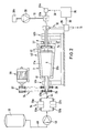
- the discharge (31) of the heavier phase (13) can be assigned a measuring device (29) for determining the solids content and via a signal line (30) and a computer unit (35) and a control line (36) can be assigned to a quantity control element (32a, 32b) in the compressed air line (19) of the compressed air liquid lifter (37), which is connected to the control element (32a) of the compressed air quantity regulator (32b) via the control line (36) is.
- the compressed air generation system has a compressed air pump (38) with a motor (38a). Via the control device (29, 35, 32) the discharge amount of the solid phase (13) is influenced in accordance with a predetermined delivery characteristic of the compressed air liquid lifter (37) so that its solids content remains constant.
- a coarse material separator (34) is connected upstream of the entry element (43a, 45).
- the suspension (44) is, for example, from a storage container (39) with the line (48) through the feed pump (49) and a switchable valve bank (50a, 50b) alternately through filter (33a) or filter (33b) into the centrifuge (40 ) fed.
- the tandem arrangement enables two-way operation, whereby the filter that is not in operation can be cleaned without interrupting operation and then switched on again in the inlet.
Landscapes
- Centrifugal Separators (AREA)
Applications Claiming Priority (2)
| Application Number | Priority Date | Filing Date | Title |
|---|---|---|---|
| DE3744093 | 1987-12-24 | ||
| DE19873744093 DE3744093A1 (de) | 1987-12-24 | 1987-12-24 | Vollmantelzentrifuge |
Publications (2)
| Publication Number | Publication Date |
|---|---|
| EP0322516A2 true EP0322516A2 (fr) | 1989-07-05 |
| EP0322516A3 EP0322516A3 (fr) | 1990-04-25 |
Family
ID=6343599
Family Applications (1)
| Application Number | Title | Priority Date | Filing Date |
|---|---|---|---|
| EP88115690A Withdrawn EP0322516A3 (fr) | 1987-12-24 | 1988-09-23 | Centrifuge à bol plein |
Country Status (4)
| Country | Link |
|---|---|
| US (1) | US4898571A (fr) |
| EP (1) | EP0322516A3 (fr) |
| JP (1) | JPH01203063A (fr) |
| DE (1) | DE3744093A1 (fr) |
Cited By (1)
| Publication number | Priority date | Publication date | Assignee | Title |
|---|---|---|---|---|
| CN110388465A (zh) * | 2019-07-26 | 2019-10-29 | 浙江轻机实业有限公司 | 一种双级推料离心机反渗漏密封方法 |
Families Citing this family (23)
| Publication number | Priority date | Publication date | Assignee | Title |
|---|---|---|---|---|
| DE4104483A1 (de) * | 1991-02-14 | 1992-08-20 | Kloeckner Humboldt Deutz Ag | Verfahren zum betreiben einer schneckenzentrifuge und zentrifuge hierfuer |
| WO1993020946A1 (fr) * | 1992-04-10 | 1993-10-28 | Warman International Limited | Appareil servant a trier et separer des materiaux |
| DE4231063A1 (de) * | 1992-09-17 | 1994-03-24 | Westfalia Separator Ag | Vollmantel-Schneckenzentrifuge zum Klären oder Trennen eines Flüssigkeits-Feststoffgemisches |
| US7479123B2 (en) | 2002-03-04 | 2009-01-20 | Therakos, Inc. | Method for collecting a desired blood component and performing a photopheresis treatment |
| US7211037B2 (en) * | 2002-03-04 | 2007-05-01 | Therakos, Inc. | Apparatus for the continuous separation of biological fluids into components and method of using same |
| DE10223802B4 (de) * | 2002-05-29 | 2005-06-09 | Westfalia Separator Ag | Vollmantel-Schneckenzentrifuge |
| DE10336350B4 (de) * | 2003-08-08 | 2007-10-31 | Westfalia Separator Ag | Vollmantel-Schneckenzentrifuge, mit Schälscheibe |
| US20050049539A1 (en) * | 2003-09-03 | 2005-03-03 | O'hara Gerald P. | Control system for driving fluids through an extracorporeal blood circuit |
| US7476209B2 (en) | 2004-12-21 | 2009-01-13 | Therakos, Inc. | Method and apparatus for collecting a blood component and performing a photopheresis treatment |
| US7603839B2 (en) * | 2005-12-22 | 2009-10-20 | Pratt & Whitney Canada Corp. | Scavenge pump system and method |
| GB0621614D0 (en) * | 2006-10-31 | 2006-12-06 | Mozley Ltd | Improvements in and relating to solids sparators |
| US8771160B2 (en) * | 2008-01-31 | 2014-07-08 | F. P. Marangoni Inc. | Gas injection-aided centrifugal separation of entrained solids from a solution |
| US9044762B2 (en) * | 2010-06-15 | 2015-06-02 | Centrisys Corp. | Centrifugal liquid separation machine using pressurized air to promote solids transport |
| KR20130031375A (ko) * | 2010-07-01 | 2013-03-28 | 로버트 하브린 | 헤비 페이즈 토출류로부터 멀티 페이즈의 고체를 효율적으로 유동하게 하는 원심 액체 분리 기계 |
| US9849466B2 (en) * | 2011-06-29 | 2017-12-26 | The University Of British Columbia | Method and apparatus for continuously fractionating particles contained within a viscoplastic fluid |
| GB201321250D0 (en) | 2013-12-02 | 2014-01-15 | Gm Innovations Ltd | An apparatus for removing impurities from a fluid stream |
| GB201703110D0 (en) | 2017-02-27 | 2017-04-12 | Gm Innovations Ltd | An apparatus for seperating components of a fluid stream |
| GB2572331B (en) | 2018-03-26 | 2022-03-09 | Gm Innovations Ltd | An apparatus for separating components of a fluid stream |
| GB2573116B (en) | 2018-04-24 | 2022-11-30 | Gm Innovations Ltd | An apparatus for producing potable water |
| CN109046794A (zh) * | 2018-08-13 | 2018-12-21 | 贵州开磷机电装备工程有限责任公司 | 一种卧螺机内部的特殊密封装置 |
| CN109320041B (zh) * | 2018-10-22 | 2023-04-18 | 长沙理工大学 | 一种泥浆处理系统 |
| DE102023121127A1 (de) * | 2023-08-08 | 2025-02-13 | Gea Westfalia Separator Group Gmbh | Vollmantel-Zentrifuge |
| DE102023126610A1 (de) * | 2023-09-29 | 2025-04-03 | Gea Westfalia Separator Group Gmbh | Vollmantel-Zentrifuge |
Family Cites Families (6)
| Publication number | Priority date | Publication date | Assignee | Title |
|---|---|---|---|---|
| US3795361A (en) * | 1972-09-06 | 1974-03-05 | Pennwalt Corp | Centrifuge apparatus |
| DD205825A1 (de) * | 1982-05-28 | 1984-01-11 | Dietrich Eichler | Vollmantel-schneckenzentrifuge |
| DE3335873A1 (de) * | 1983-07-25 | 1985-02-21 | Klöckner-Humboldt-Deutz AG, 5000 Köln | Vollmantel-schneckenzentrifuge zur trennung eines feststoff-fluessigkeitsgemisches |
| US4566873A (en) * | 1984-03-28 | 1986-01-28 | Kotobuki Engineering & Manufacturing Co., Ltd. | Screw decanter type centrifugal concentrating machine |
| DE3608664A1 (de) * | 1986-03-14 | 1987-09-17 | Krauss Maffei Ag | Vollmantelzentrifuge |
| AU607750B2 (en) * | 1987-04-21 | 1991-03-14 | Robert Edward High | Decanter centrifuge incorporating airlift device |
-
1987
- 1987-12-24 DE DE19873744093 patent/DE3744093A1/de not_active Withdrawn
-
1988
- 1988-09-23 EP EP88115690A patent/EP0322516A3/fr not_active Withdrawn
- 1988-11-30 US US07/277,978 patent/US4898571A/en not_active Expired - Fee Related
- 1988-12-23 JP JP63323809A patent/JPH01203063A/ja active Pending
Cited By (1)
| Publication number | Priority date | Publication date | Assignee | Title |
|---|---|---|---|---|
| CN110388465A (zh) * | 2019-07-26 | 2019-10-29 | 浙江轻机实业有限公司 | 一种双级推料离心机反渗漏密封方法 |
Also Published As
| Publication number | Publication date |
|---|---|
| DE3744093A1 (de) | 1989-07-13 |
| EP0322516A3 (fr) | 1990-04-25 |
| US4898571A (en) | 1990-02-06 |
| JPH01203063A (ja) | 1989-08-15 |
Similar Documents
| Publication | Publication Date | Title |
|---|---|---|
| EP0322516A2 (fr) | Centrifuge à bol plein | |
| DE2344507C2 (de) | Vollmantel-Schneckenzentrifuge | |
| DE3202294C1 (de) | Kontinuierlich arbeitender Vollmantel-Gegenstrom-Zentrifugalextraktor | |
| EP2326493B1 (fr) | Filtre-presse à vis sans fin | |
| DE3318793A1 (de) | Vorrichtung zum entfeuchten von schlamm | |
| DE3224204A1 (de) | Zentrifuge | |
| DE2130633A1 (de) | Vollmantelschneckenzentrifuge | |
| WO2003078070A1 (fr) | Centrifugeuse a vis sans fin | |
| DE3874943T2 (de) | Dekantierzentrifuge mit pneumatischer entleerungsvorrichtung. | |
| DE3328303C1 (de) | Vorrichtung zum Entwaessern und Trocknen von Kunststoffgranulat | |
| DE3904151A1 (de) | Zentrifuge | |
| DE102018113135A1 (de) | Vorrichtung zur Klärschlammentwässerung | |
| DE60124554T2 (de) | Zentrifugalabscheider | |
| DE69102002T2 (de) | Dekantierzentrifuge. | |
| EP0163112B1 (fr) | Procédé et dispositif pour la séparation centrifuge de mélanges de minéraux à grains fins | |
| DE1632324A1 (de) | Trichterzentrifuge | |
| EP0012461B1 (fr) | Installation de gazéification de charbon | |
| DE1532711B1 (de) | Kontinuierlich arbeitende Vollmantelzentrifuge | |
| DE102019128562A1 (de) | Vollmantel-Schneckenzentrifuge | |
| CH433192A (de) | Einrichtung zur Abscheidung und Fraktionierung von in einer Flüssigkeit gelöstem oder suspendiertem Material | |
| EP0998341A1 (fr) | Procede et dispositif pour separer des matieres, et dispositif de guidage utilise a cet effet | |
| DE102020114665B4 (de) | Durchlaufzentrifuge | |
| DE2152839A1 (de) | Gleichstrom-vollmantelzentrifuge mit beschleunigungskoerper | |
| DE4041923A1 (de) | Vollmantel-schneckenzentrifuge | |
| DE723408C (de) | Vollmantelschleuder zum Abscheiden von Fluessigkeiten aus breiigem oder vorwiegend fluessigem Gut |
Legal Events
| Date | Code | Title | Description |
|---|---|---|---|
| PUAI | Public reference made under article 153(3) epc to a published international application that has entered the european phase |
Free format text: ORIGINAL CODE: 0009012 |
|
| AK | Designated contracting states |
Kind code of ref document: A2 Designated state(s): DE FR GB IT NL SE |
|
| PUAL | Search report despatched |
Free format text: ORIGINAL CODE: 0009013 |
|
| AK | Designated contracting states |
Kind code of ref document: A3 Designated state(s): DE FR GB IT NL SE |
|
| STAA | Information on the status of an ep patent application or granted ep patent |
Free format text: STATUS: THE APPLICATION IS DEEMED TO BE WITHDRAWN |
|
| 18D | Application deemed to be withdrawn |
Effective date: 19901026 |