EP0322524A1 - Servofrein en tandem pour véhicules à moteur - Google Patents
Servofrein en tandem pour véhicules à moteur Download PDFInfo
- Publication number
- EP0322524A1 EP0322524A1 EP88117007A EP88117007A EP0322524A1 EP 0322524 A1 EP0322524 A1 EP 0322524A1 EP 88117007 A EP88117007 A EP 88117007A EP 88117007 A EP88117007 A EP 88117007A EP 0322524 A1 EP0322524 A1 EP 0322524A1
- Authority
- EP
- European Patent Office
- Prior art keywords
- control housing
- brake booster
- tandem brake
- booster according
- chamber
- Prior art date
- Legal status (The legal status is an assumption and is not a legal conclusion. Google has not performed a legal analysis and makes no representation as to the accuracy of the status listed.)
- Granted
Links
Images


Classifications
-
- B—PERFORMING OPERATIONS; TRANSPORTING
- B60—VEHICLES IN GENERAL
- B60T—VEHICLE BRAKE CONTROL SYSTEMS OR PARTS THEREOF; BRAKE CONTROL SYSTEMS OR PARTS THEREOF, IN GENERAL; ARRANGEMENT OF BRAKING ELEMENTS ON VEHICLES IN GENERAL; PORTABLE DEVICES FOR PREVENTING UNWANTED MOVEMENT OF VEHICLES; VEHICLE MODIFICATIONS TO FACILITATE COOLING OF BRAKES
- B60T13/00—Transmitting braking action from initiating means to ultimate brake actuator with power assistance or drive; Brake systems incorporating such transmitting means, e.g. air-pressure brake systems
- B60T13/10—Transmitting braking action from initiating means to ultimate brake actuator with power assistance or drive; Brake systems incorporating such transmitting means, e.g. air-pressure brake systems with fluid assistance, drive, or release
- B60T13/24—Transmitting braking action from initiating means to ultimate brake actuator with power assistance or drive; Brake systems incorporating such transmitting means, e.g. air-pressure brake systems with fluid assistance, drive, or release the fluid being gaseous
- B60T13/46—Vacuum systems
- B60T13/52—Vacuum systems indirect, i.e. vacuum booster units
- B60T13/563—Vacuum systems indirect, i.e. vacuum booster units with multiple booster units, e.g. tandem booster units
Definitions
- the invention relates to a tandem brake booster for motor vehicles with a housing, the interior of which is divided into a front and a rear booster chamber with the aid of a partition, with a first and a second movable wall which separate the front and the rear booster chamber into a first vacuum chamber and subdivide the first working chamber or a second vacuum chamber and a second working chamber, a control housing which is displaceable in the actuating direction and has a valve device arranged therein, which can be actuated by means of an actuating rod connected to a brake pedal and controls the passage of outside air into the working chambers, and with one the control housing cooperating push rod, which transmits the braking force to an actuating piston of a master cylinder attached to the housing, both the vacuum chambers and the working chambers being connected to one another in an area which is within their radially inner boundary.
- Such a tandem brake booster is known for example from DE-OS 33 o3 577.
- the special feature of this brake booster is that the connection of the two working chambers is attached to the control housing by means of a guide tube which is pushed onto the control housing and which is concentric with the guide tube
- Metallic sleeve limited annular gap takes place while the vacuum chambers are connected to each other via vacuum channels formed in the control housing and radially limited by the inner wall of the sleeve.
- the guide tube extends into the front working chamber and protrudes through a partition dividing the amplifier housing into two amplifier spaces, which is sealed off from the guide tube by means of a sealing ring.
- the annular gap is divided into individual ventilation channels by a plurality of radial ribs formed on the inner diameter, the front movable wall being operatively connected to the control housing via the sleeve.
- tandem brake booster the need to use several individual parts for simultaneous ventilation of the working chambers is less advantageous, which, with regard to their sealing, in particular in the area of the partition on the surface of the guide tube and the two O-rings sealing the sleeve from the control housing, is considerable Cause problems.
- tandem brake booster of the type mentioned at the beginning, the further development of which consists in that the transmission of the amplifier force of the first movable wall takes place directly on the control housing.
- a tandem brake booster for motor vehicles is thus created, in which a considerable increase in operational safety is achieved using inexpensive individual parts. At the same time, its essential simplification and weight reduction are achieved.
- the first movable wall is arranged on an axial extension of the control housing, which extends through the partition and extends into the first amplifier chamber. This measure enables the poppet valve to be displaced into the interior of the booster housing, as a result of which the length of the external air passages can be optimized.
- a further advantageous development of the subject matter of the invention provides that both the connection of the first and the second vacuum chamber and the connection of the two working chambers takes place by means of vacuum or ventilation channels formed in the control housing. Since the axially extending channels can be molded into the control housing by means of cross slides, this measure enables them to be optimally designed.
- a perfect sealing of the partition against the control housing is achieved in that the ventilation channels formed as axial grooves in the control housing are radially limited by means of a sealing sleeve which is arranged in a sealed manner on the extension of the control housing.
- a particularly stable embodiment of the subject matter of the invention is achieved in that the second movable wall on the control housing is arranged adjacent to the sealing sleeve, so that the reinforcing force is transmitted to the control housing via the sealing sleeve.
- the sealing sleeve is provided with a collar which interacts with an annular surface formed on the control housing.
- tandem brake booster according to the invention, results from the following description of two exemplary embodiments of the invention, which are explained in more detail with reference to the accompanying drawing, the corresponding parts being provided with the same reference numerals.
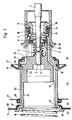
- the tandem brake booster shown in FIGS. 1, 3 and 4 has a housing which is formed by two shell-shaped housing halves 1, 2, which are held together with the aid of a clamping ring 3.
- the interior of the housing is divided into a front (master cylinder-side) booster chamber 20 and a rear (brake pedal-side) booster room 21 by means of a partition 41 arranged therein, the front booster room 20 being separated by a first movable wall 14 into a first vacuum chamber 32 of constant pressure and first working chamber 24 of variable pressure and the rear booster chamber 21 are divided by a second movable wall 15 into a second vacuum chamber 33 and a second working chamber 25.
- the front housing half 1 is provided with a vacuum connection 11, by means of which the first vacuum chamber 32 can be connected to a suitable vacuum source, for example an intake manifold of the motor vehicle engine.
- a two-part control housing 4 which is formed by a guide part 44 and a front part 45, is guided in an axial section of smaller diameter of the rear housing half 2.
- a control rod composed of a piston rod 7 and a valve piston 6 is arranged axially displaceably in the interior of the control housing 4 and is connected via a fork head 49 to a brake pedal (not shown) of a motor vehicle.
- the control housing 4 also contains a valve arrangement 8, 37, 38, which is actuated by valve piston 6 and via vacuum channels 34 and ventilation channels 19 controls the pressure difference between the vacuum chambers 32, 33 and the working chambers 24, 25.
- the front part 45 of the control housing 4, which carries the second movable wall 15, has an axial bore 5, in which the valve piston 6 is displaceably guided and which merges into a section of larger diameter, in which a transmission disk 29 is arranged, which is provided with a rubber-elastic reaction disk 9 cooperates, which is in a force-transmitting connection with a push rod 10 actuating a master cylinder, not shown.
- the front part 45 of the control housing 4 finally has an axial extension 22 which extends into the first vacuum chamber 32 and extends through the partition 41 and is sealed at the passage point by means of a sealing ring 28.
- a return spring 16 is provided, which is clamped between the housing half 1 on the master cylinder side and an annular surface 46 formed on the axial extension 22 at its front end.
- the first movable wall 14 has a first rolling membrane 30 which bears against it in the first working chamber 24 and which, with its inner portion, engages around the inner edge of the first movable wall 14, while the bulge 27 seals the movable wall 14 from the axial extension 22.
- the movable wall 14 is axially supported on a radial annular collar 26 formed on the extension 22 of the control housing 4 or 45.
- the ventilation channels 19, which are preferably designed as axial grooves in the front part 45 of the control housing 4, become radial limited to the outside by means of a sealing sleeve 23 pushed onto the axial extension 22, the collar 47 of which cooperates with an annular surface 48 on the front part 45 of the control housing 4.
- the front part 45 is provided with a radial groove 42, in which an O-ring 43 which seals the sealing sleeve 23 with respect to the front part 45 is arranged.
- the arrangement of the second movable wall 15 on the front part 45 of the control housing 4 is preferably such that a second rolling membrane 31, encompassing the inner edge of the second movable wall 15, is buttoned in the front part 45 of the control housing 4, the radially inner portion of the movable Wall 15 is axially supported on the sealing sleeve 23, so that the transmission of the reinforcing force of the second movable wall 15 to the control housing 4 takes place via the sealing sleeve 23.
- the connection of the second vacuum chamber 33 to the vacuum channels 34 formed in the front part 45 of the control housing 4 is made possible by a plurality of passage openings 36 with which the sealing sleeve 23 is provided in the region of its end on the control piston side.
- the control assembly of the vacuum brake booster is shown in the release position, ie in a position in which the two vacuum chambers 32, 33 are separated from the working chambers 24, 25.
- the two sealing seats 37, 38 rest against the sealing surface of the poppet valve 8, which has a stop on its side facing away from the sealing surface, which abuts on the guide part 44 via a sleeve 13.
- the guide part 44 lies with its collar 39 on a sliding guide ring 56, the sealing seat 37 on the valve piston 6 is pressed by a piston rod return spring 17 against the sealing surface of the poppet valve 8.
- the poppet valve 8 is simultaneously biased towards the two sealing seats 37, 38 by means of a compression spring 40 which is supported on the sleeve 13 at its other end.
- a second compression spring 18 is provided, which is supported on the one hand on a guide 51 of the poppet valve 8 and on the other hand on an annular surface 50 of the sleeve 13 and keeps the two control housing parts 44, 45 apart.
- the ventilation channels 19 are formed by axial passages 55 formed in the axial extension 22 or the front part 45 of the control housing 4.
- the amplification force is transmitted directly to the front part 45 of the control housing 4, specifically by means of an annular surface 52 which is formed on the second movable wall 15 and extends radially inwards and which is located in the fastening region of the second movable wall 15 directly on the front part 45 of the control housing 4 axially supported.
- the second vacuum chamber 33 is sealed off from the ventilation channels 19 by means of a sealing ring 54 arranged in an annular groove 53 formed in the surface of the front part 45.
Landscapes
- Engineering & Computer Science (AREA)
- Transportation (AREA)
- Mechanical Engineering (AREA)
- Braking Systems And Boosters (AREA)
Applications Claiming Priority (2)
| Application Number | Priority Date | Filing Date | Title |
|---|---|---|---|
| DE3744012 | 1987-12-24 | ||
| DE19873744012 DE3744012A1 (de) | 1987-12-24 | 1987-12-24 | Tandembremskraftverstaerker fuer kraftfahrzeuge |
Publications (2)
| Publication Number | Publication Date |
|---|---|
| EP0322524A1 true EP0322524A1 (fr) | 1989-07-05 |
| EP0322524B1 EP0322524B1 (fr) | 1991-08-07 |
Family
ID=6343544
Family Applications (1)
| Application Number | Title | Priority Date | Filing Date |
|---|---|---|---|
| EP19880117007 Expired - Lifetime EP0322524B1 (fr) | 1987-12-24 | 1988-10-13 | Servofrein en tandem pour véhicules à moteur |
Country Status (5)
| Country | Link |
|---|---|
| US (1) | US5040450A (fr) |
| EP (1) | EP0322524B1 (fr) |
| JP (1) | JPH023566A (fr) |
| DE (2) | DE3744012A1 (fr) |
| ES (1) | ES2023999B3 (fr) |
Cited By (1)
| Publication number | Priority date | Publication date | Assignee | Title |
|---|---|---|---|---|
| GB2248662A (en) * | 1990-10-12 | 1992-04-15 | Jidosha Kiki Co | Brake booster |
Families Citing this family (10)
| Publication number | Priority date | Publication date | Assignee | Title |
|---|---|---|---|---|
| JP2760132B2 (ja) * | 1990-04-12 | 1998-05-28 | 自動車機器株式会社 | 倍力装置 |
| JP2753371B2 (ja) * | 1990-04-05 | 1998-05-20 | 自動車機器株式会社 | 負圧倍力装置 |
| US5142964A (en) * | 1990-04-05 | 1992-09-01 | Jidosha Kiki Co., Ltd. | Negative pressure booster |
| JP2527756Y2 (ja) * | 1990-11-28 | 1997-03-05 | 自動車機器株式会社 | タンデム倍力装置 |
| JP2537332Y2 (ja) * | 1991-02-22 | 1997-05-28 | 自動車機器株式会社 | タンデム型ブレーキ倍力装置 |
| DE4127000A1 (de) * | 1991-08-16 | 1993-02-18 | Teves Gmbh Alfred | Betaetigungseinheit fuer eine hydraulische kraftfahrzeugbremsanlage |
| DE4341838A1 (de) * | 1993-12-08 | 1995-06-14 | Teves Gmbh Alfred | Unterdruckbremskraftverstärker für Kraftfahrzeuge |
| DE19519699A1 (de) * | 1995-05-30 | 1996-12-05 | Teves Gmbh Alfred | Unterdruckbremskraftverstärker |
| US6209442B1 (en) * | 1999-08-16 | 2001-04-03 | Delphi Technologies, Inc. | Brake booster with compressible air valve for braking speed of application enhancement |
| DE102005025250A1 (de) * | 2004-10-15 | 2006-05-11 | Continental Teves Ag & Co. Ohg | Bremskraftverstärker |
Citations (4)
| Publication number | Priority date | Publication date | Assignee | Title |
|---|---|---|---|---|
| US3613506A (en) * | 1969-07-17 | 1971-10-19 | Bendix Corp | Servomotor having improved no-power operation |
| US4069742A (en) * | 1976-06-21 | 1978-01-24 | General Motors Corporation | Power brake booster system |
| DE2908481A1 (de) * | 1979-03-05 | 1980-09-11 | Teves Gmbh Alfred | Zweikreisiger vakuumverstaerker |
| DE3303577A1 (de) * | 1983-02-03 | 1984-08-09 | Alfred Teves Gmbh, 6000 Frankfurt | Bremskraftverstaerker fuer ein kraftfahrzeug |
Family Cites Families (11)
| Publication number | Priority date | Publication date | Assignee | Title |
|---|---|---|---|---|
| DE1555763A1 (de) * | 1966-02-01 | 1969-06-12 | Ernst Heinkel Ag | Pneumatisch-hydraulische Mehrkammer-Hilfskraftvorrichtung mit hydraulischem Mehrkammer-Zylinder |
| US3603208A (en) * | 1969-06-30 | 1971-09-07 | Bendix Corp | Servomotor having a one-piece center plate |
| JPS4915189A (fr) * | 1972-05-31 | 1974-02-09 | ||
| JPS5610604Y2 (fr) * | 1977-03-19 | 1981-03-10 | ||
| US4512237A (en) * | 1982-01-16 | 1985-04-23 | Jidosha Kiki Co., Ltd. | Tandem type brake power servo booster |
| JPS6058471U (ja) * | 1983-09-30 | 1985-04-23 | アイシン精機株式会社 | タンデム型ブレ−キブ−スタ |
| JPS60125271U (ja) * | 1984-02-02 | 1985-08-23 | アイシン精機株式会社 | タンデム型倍力装置 |
| JPS60157361U (ja) * | 1984-03-23 | 1985-10-19 | アイシン精機株式会社 | タンデム型倍力装置 |
| DE3505626A1 (de) * | 1985-02-19 | 1986-08-21 | Alfred Teves Gmbh, 6000 Frankfurt | Bremskraftverstaerker |
| JPS62134366A (ja) * | 1985-12-06 | 1987-06-17 | Jidosha Kiki Co Ltd | タンデムブレ−キ倍力装置 |
| JPS6382669U (fr) * | 1986-11-20 | 1988-05-31 |
-
1987
- 1987-12-24 DE DE19873744012 patent/DE3744012A1/de not_active Withdrawn
-
1988
- 1988-10-13 ES ES88117007T patent/ES2023999B3/es not_active Expired - Lifetime
- 1988-10-13 DE DE8888117007T patent/DE3864132D1/de not_active Expired - Lifetime
- 1988-10-13 EP EP19880117007 patent/EP0322524B1/fr not_active Expired - Lifetime
- 1988-11-29 US US07/277,580 patent/US5040450A/en not_active Expired - Fee Related
- 1988-12-23 JP JP63325745A patent/JPH023566A/ja active Pending
Patent Citations (4)
| Publication number | Priority date | Publication date | Assignee | Title |
|---|---|---|---|---|
| US3613506A (en) * | 1969-07-17 | 1971-10-19 | Bendix Corp | Servomotor having improved no-power operation |
| US4069742A (en) * | 1976-06-21 | 1978-01-24 | General Motors Corporation | Power brake booster system |
| DE2908481A1 (de) * | 1979-03-05 | 1980-09-11 | Teves Gmbh Alfred | Zweikreisiger vakuumverstaerker |
| DE3303577A1 (de) * | 1983-02-03 | 1984-08-09 | Alfred Teves Gmbh, 6000 Frankfurt | Bremskraftverstaerker fuer ein kraftfahrzeug |
Cited By (2)
| Publication number | Priority date | Publication date | Assignee | Title |
|---|---|---|---|---|
| GB2248662A (en) * | 1990-10-12 | 1992-04-15 | Jidosha Kiki Co | Brake booster |
| GB2248662B (en) * | 1990-10-12 | 1994-06-29 | Jidosha Kiki Co | Brake booster |
Also Published As
| Publication number | Publication date |
|---|---|
| US5040450A (en) | 1991-08-20 |
| DE3744012A1 (de) | 1989-07-06 |
| EP0322524B1 (fr) | 1991-08-07 |
| ES2023999B3 (es) | 1992-02-16 |
| JPH023566A (ja) | 1990-01-09 |
| DE3864132D1 (de) | 1991-09-12 |
Similar Documents
| Publication | Publication Date | Title |
|---|---|---|
| DE2920249C2 (fr) | ||
| DE2735847A1 (de) | Tandem-hauptzylinder | |
| DE3503444A1 (de) | Tandembremskraftverstaerker fuer kraftfahrzeuge | |
| EP0322524A1 (fr) | Servofrein en tandem pour véhicules à moteur | |
| EP0318681B1 (fr) | Servofrein à vide pour véhicules à moteur | |
| EP0347583A2 (fr) | Moteur à vide pour installations de freinage dans des véhicules | |
| EP0383050A1 (fr) | Servofrein à vide | |
| DE2918912A1 (de) | Bremskraftverstaerker | |
| DE3018270C2 (fr) | ||
| DE3107918C2 (fr) | ||
| WO1993018948A1 (fr) | Servofrein a depression | |
| DE3806401A1 (de) | Bremskraftverstaerker | |
| DE2908481A1 (de) | Zweikreisiger vakuumverstaerker | |
| EP0434782B1 (fr) | Bloc de commande pour circuit de freinage hydraulique d'un vehicule automobile | |
| DE2650490C2 (de) | Pneumatisch oder hydraulisch gesteuerte Scheibenbremse | |
| DE1655969A1 (de) | Druckmittel-Servomotor,insbesondere fuer Servobremssysteme fuer Kraftfahrzeuge | |
| DE4301336A1 (de) | Betätigungseinheit für eine blockiergeschützte Kraftfahrzeugbremsanlage | |
| EP0681539A1 (fr) | Servofrein a depression pour vehicules | |
| DE69618242T2 (de) | Bremskraftverstärker mit verbessertem ventil | |
| DE69312173T2 (de) | Pneumatische Kraftverstärker für Fahrzeugbremsanlagen | |
| DE3012455C2 (fr) | ||
| WO1995025029A1 (fr) | Groupe d'actionnement pour systeme de freinage de vehicule automobile | |
| DE69618243T2 (de) | Pneumatischer bremskraftverstärker mit verbessertem ventil | |
| DE19539601B4 (de) | Unterdruckbremskraftverstärker für Kraftfahrzeuge | |
| DE2606502C3 (de) | Tandemhauptzylinder für eine hydraulische Fahrzeugbremsanlage |
Legal Events
| Date | Code | Title | Description |
|---|---|---|---|
| PUAI | Public reference made under article 153(3) epc to a published international application that has entered the european phase |
Free format text: ORIGINAL CODE: 0009012 |
|
| 17P | Request for examination filed |
Effective date: 19881013 |
|
| AK | Designated contracting states |
Kind code of ref document: A1 Designated state(s): DE ES FR GB IT |
|
| ITF | It: translation for a ep patent filed | ||
| 17Q | First examination report despatched |
Effective date: 19901031 |
|
| GRAA | (expected) grant |
Free format text: ORIGINAL CODE: 0009210 |
|
| AK | Designated contracting states |
Kind code of ref document: B1 Designated state(s): DE ES FR GB IT |
|
| GBT | Gb: translation of ep patent filed (gb section 77(6)(a)/1977) | ||
| REF | Corresponds to: |
Ref document number: 3864132 Country of ref document: DE Date of ref document: 19910912 |
|
| ET | Fr: translation filed | ||
| REG | Reference to a national code |
Ref country code: ES Ref legal event code: FG2A Ref document number: 2023999 Country of ref document: ES Kind code of ref document: B3 |
|
| RIN2 | Information on inventor provided after grant (corrected) |
Free format text: JAKOBI, RALF * BOEHM,PETER |
|
| PLBE | No opposition filed within time limit |
Free format text: ORIGINAL CODE: 0009261 |
|
| STAA | Information on the status of an ep patent application or granted ep patent |
Free format text: STATUS: NO OPPOSITION FILED WITHIN TIME LIMIT |
|
| 26N | No opposition filed | ||
| PGFP | Annual fee paid to national office [announced via postgrant information from national office to epo] |
Ref country code: ES Payment date: 19971017 Year of fee payment: 10 |
|
| PG25 | Lapsed in a contracting state [announced via postgrant information from national office to epo] |
Ref country code: ES Free format text: LAPSE BECAUSE OF THE APPLICANT RENOUNCES Effective date: 19981014 |
|
| PGFP | Annual fee paid to national office [announced via postgrant information from national office to epo] |
Ref country code: GB Payment date: 20000925 Year of fee payment: 13 |
|
| PGFP | Annual fee paid to national office [announced via postgrant information from national office to epo] |
Ref country code: DE Payment date: 20001031 Year of fee payment: 13 |
|
| REG | Reference to a national code |
Ref country code: ES Ref legal event code: FD2A Effective date: 20001009 |
|
| PG25 | Lapsed in a contracting state [announced via postgrant information from national office to epo] |
Ref country code: GB Free format text: LAPSE BECAUSE OF NON-PAYMENT OF DUE FEES Effective date: 20011013 |
|
| PGFP | Annual fee paid to national office [announced via postgrant information from national office to epo] |
Ref country code: FR Payment date: 20011018 Year of fee payment: 14 |
|
| REG | Reference to a national code |
Ref country code: GB Ref legal event code: IF02 |
|
| GBPC | Gb: european patent ceased through non-payment of renewal fee |
Effective date: 20011013 |
|
| PG25 | Lapsed in a contracting state [announced via postgrant information from national office to epo] |
Ref country code: DE Free format text: LAPSE BECAUSE OF NON-PAYMENT OF DUE FEES Effective date: 20020702 |
|
| PG25 | Lapsed in a contracting state [announced via postgrant information from national office to epo] |
Ref country code: FR Free format text: LAPSE BECAUSE OF NON-PAYMENT OF DUE FEES Effective date: 20030630 |
|
| REG | Reference to a national code |
Ref country code: FR Ref legal event code: ST |
|
| PG25 | Lapsed in a contracting state [announced via postgrant information from national office to epo] |
Ref country code: IT Free format text: LAPSE BECAUSE OF NON-PAYMENT OF DUE FEES;WARNING: LAPSES OF ITALIAN PATENTS WITH EFFECTIVE DATE BEFORE 2007 MAY HAVE OCCURRED AT ANY TIME BEFORE 2007. THE CORRECT EFFECTIVE DATE MAY BE DIFFERENT FROM THE ONE RECORDED. Effective date: 20051013 |