EP0322566B1 - Procédé et dispositif pour la fabrication d'un support métallique pour réacteurs catalytiques - Google Patents
Procédé et dispositif pour la fabrication d'un support métallique pour réacteurs catalytiques Download PDFInfo
- Publication number
- EP0322566B1 EP0322566B1 EP88119629A EP88119629A EP0322566B1 EP 0322566 B1 EP0322566 B1 EP 0322566B1 EP 88119629 A EP88119629 A EP 88119629A EP 88119629 A EP88119629 A EP 88119629A EP 0322566 B1 EP0322566 B1 EP 0322566B1
- Authority
- EP
- European Patent Office
- Prior art keywords
- metal strips
- winding
- stack
- carrier body
- metal
- Prior art date
- Legal status (The legal status is an assumption and is not a legal conclusion. Google has not performed a legal analysis and makes no representation as to the accuracy of the status listed.)
- Expired - Lifetime
Links
Images


Classifications
-
- F—MECHANICAL ENGINEERING; LIGHTING; HEATING; WEAPONS; BLASTING
- F01—MACHINES OR ENGINES IN GENERAL; ENGINE PLANTS IN GENERAL; STEAM ENGINES
- F01N—GAS-FLOW SILENCERS OR EXHAUST APPARATUS FOR MACHINES OR ENGINES IN GENERAL; GAS-FLOW SILENCERS OR EXHAUST APPARATUS FOR INTERNAL-COMBUSTION ENGINES
- F01N3/00—Exhaust or silencing apparatus having means for purifying, rendering innocuous, or otherwise treating exhaust
- F01N3/08—Exhaust or silencing apparatus having means for purifying, rendering innocuous, or otherwise treating exhaust for rendering innocuous
- F01N3/10—Exhaust or silencing apparatus having means for purifying, rendering innocuous, or otherwise treating exhaust for rendering innocuous by thermal or catalytic conversion of noxious components of exhaust
- F01N3/24—Exhaust or silencing apparatus having means for purifying, rendering innocuous, or otherwise treating exhaust for rendering innocuous by thermal or catalytic conversion of noxious components of exhaust characterised by constructional aspects of converting apparatus
- F01N3/28—Construction of catalytic reactors
- F01N3/2803—Construction of catalytic reactors characterised by structure, by material or by manufacturing of catalyst support
- F01N3/2807—Metal other than sintered metal
- F01N3/281—Metallic honeycomb monoliths made of stacked or rolled sheets, foils or plates
- F01N3/2817—Metallic honeycomb monoliths made of stacked or rolled sheets, foils or plates only with non-corrugated sheets, plates or foils
-
- F—MECHANICAL ENGINEERING; LIGHTING; HEATING; WEAPONS; BLASTING
- F01—MACHINES OR ENGINES IN GENERAL; ENGINE PLANTS IN GENERAL; STEAM ENGINES
- F01N—GAS-FLOW SILENCERS OR EXHAUST APPARATUS FOR MACHINES OR ENGINES IN GENERAL; GAS-FLOW SILENCERS OR EXHAUST APPARATUS FOR INTERNAL-COMBUSTION ENGINES
- F01N2330/00—Structure of catalyst support or particle filter
- F01N2330/02—Metallic plates or honeycombs, e.g. superposed or rolled-up corrugated or otherwise deformed sheet metal
- F01N2330/04—Methods of manufacturing
Definitions
- the invention relates to a method according to the preamble of claim 1 and a device for carrying it out.
- carrier bodies for catalytic reactors for exhaust gas purification by winding from two metal strips, one of which is corrugated and the other is designed as a smooth strip.
- the smooth metal strip is wound directly adjacent to the corrugated strip, so that it prevents adjacent layers of corrugated strips from slipping into one another.
- carrier bodies by winding only a single strip of corresponding cross-sectional shape, in which, due to the cross-section of the corrugations, slipping of adjacent layers is avoided.
- a catalyst carrier body is known from EP-A 0 245 736, in which the individual layers run approximately involute-shaped from the center to the outside to a jacket tube. The ends of these individual layers are said to be fastened to the casing tube.
- the content of this document leaves open the manner in which the carrier body shown there is to be produced.
- the invention is therefore based on the object of creating a method of the type mentioned, in which the same the known winding technology a radially flexible support body can be created, which can be easily connected to a sleeve and also reduces the risk that this connection is affected by thermal expansion.
- claims 1 and 10 are proposed.
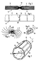
- a cohesion of a carrier matrix formed in this way is essentially ensured by the outer jacket sleeve, because the individual metal bands tend to spread outwards, at least in the outer region of the carrier body, due to the inherent elasticity thereof. Since the free ends of the individual metal strips can also be distributed uniformly around the circumference of the finished carrier body by the multi-course winding process, a uniformly elastic carrier body is created which can be connected to the jacket sleeve in a very simple and safe manner. Thermal expansion can also be absorbed excellently by the new carrier body.
- each metal strip is provided with incisions in the region of its center and that the web that remains in this way is gripped, squeezed flat and rotated between the incisions.
- the new process can be put into practice in various ways. According to claim 2, it is particularly economical to form a stack from the metal strips and to grasp this at one of its ends. According to claim 3, the stack can also be formed during winding, the ends of the individual metal strips being introduced and held one after the other during the winding process of the first metal strip in the clamping gap formed by this with a winding core or between two layers of metal strips.
- the end of the stack of the end of the outermost metal strip or of the to form aligned end faces of two or more of the outer metal strips, on which outer metal strip all other metal strips are attached with their ends offset to one another in such a way that a parallelepiped-shaped stack is formed which is wound up so that all the ends of the metal strips are directed towards the winding axis .
- a new device for carrying out the winding process of the invention provides a winding core with at least two drivers provided on its circumference, to which the ends of the metal strips supplied by a feed arrangement can be fastened.
- the resilient tongues press against the clamping surfaces during the winding process.
- they can be axially loosened very easily by releasing the clamping effect by turning back slightly in the opposite direction Pull out together with the winding core.
- the carrier body thus provided with a cavity in the center can then, as mentioned at the beginning, be deformed or completed by inserting an additional winding body into a cylindrical final shape.
- a characteristic, multi-course, spirally wound carrier body is formed, which is characterized by a large number of independent, mutually spirally starting metal bands with their free ends lying on the outside of the jacket.
- Such a carrier body has the advantageous features of good radial extensibility described at the outset.
- a different manufacturing possibility based on the same principle is sketched, in which first a stack (13) of superimposed bands (5, 6) is formed, which in the middle, in the area (5d), from the dash-dotted starting form is compressed to the extended form.
- This middle area (5d) thus more or less, compared to the representation according to FIG. 1, represents the fastening area for the front ends (5a and 5a ') (see FIG. 4) of two bands (5 and 5'), which can then be wound into a multi-layer spiral carrier body by twisting around the region (5d), as shown in FIG. 5, in a similar manner as is also the case was shown with reference to FIG. 1.
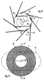
- the area (5d) can be pressed together before the stack (13) is clamped, with lateral slits to form the ends () to facilitate the compression and to facilitate good deflection of the strips in the area (5d) during the subsequent winding.
- 5a, 5a ') of the bands (5 and 5') can be provided.
- the area (5d) can then, for example, be inserted axially into the gap (27) between two prongs (28 and 28a) of a fork-shaped part (29) until an edge of the stack (13) on the rear pane part of the part (29) is present.
- the support body can then be formed by rotation in the direction of the arrow (32) of the part (29) about the winding axis (9).
- Damage to the flow channels between the individual layers (5 and 6) can largely be avoided in the manufacture of the region (5d) by the shape of the crimping tool and by the shape of the prongs (28 and 28a).
- the fork-shaped tines (28 and 28a) are pulled axially out of the carrier body after the body has been wound up. They can be dimensioned correspondingly small in order to avoid an undesirable formation of cavities in the center of the carrier body.
- the front end (7a) is made up of a plurality of bands (7), each of which is formed from a corrugated band and a smooth band are clamped on a rotating winding body (19) in cylindrical shape, which is later pulled out axially after the manufacture of the carrier body in the form shown in FIG. 9.
- the support body (10) can be deformed by pressure in the direction of the arrows (33) in a manner known per se to an oval and elliptical support body, as it is with (34) in its Contour is indicated schematically. In such a process, which is known per se, the initially cylindrical cavity (8) is compressed.
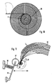
- a further spirally wound cylindrical support body (11) in the initially sleeve-shaped support body (10) of FIG. 9. This can be done either by axially pressing the carrier body (11) into the cavity. It is also possible to first wrap the carrier body (11) up to a certain diameter in a known manner and then to wrap more metal strips between the respective outer layers of this carrier body, which serves as the winding core.
- This process can also be carried out by feeding these end faces (7a) tangentially to the stationary winding core, to the extent that they lie approximately on the clamping surfaces (26).
- the sleeve (20) can then be pushed axially over the winding core and over the front ends.
- the individual metal strips (7) are guided tangentially to the winding body (19). This could be done, for example, by unwinding supply rolls, the axes of which are arranged parallel to the winding axis (9) and which are provided concentrically around the winding core (19) at a sufficient distance. Corresponding cutting devices for cutting the individual strips (7) to length could also be arranged.
- the axes of the twelve supply rolls to be arranged in the exemplary embodiment and the winding axis (9) could be arranged vertically on a base frame or horizontally on a corresponding guide wall.
- carrier bodies according to FIG. 9 or according to FIG. 10 can be produced.
- Fig. 11 shows a possibility of feeding several tapes, each of which is stored in the shafts of a feed magazine subdivided by partition walls (30) in such a way that their front ends (7a) converge in the region of a winding body (12 ').
- a on a lever (36) pivotally arranged roller (37), which is under the force of a compression spring (38), ensures when the metal strips (7) rotate about the winding axis (9) in the direction of the arrow (32) that the bundle of metal strips (7), which are initially introduced at least in part into a slot in the winding body (12 ') with their ends (7a), are always pressed firmly against the spirally wound carrier body during the winding process.
- the two outermost metal strips lying in the magazine are gripped in the slot of the winding body (12 ') and ensure that the intermediate metal strips are pulled along with the further winding movement.
- FIGS. 12 and 13 Another very advantageous possibility of producing the new carrier body is indicated in FIGS. 12 and 13.
- a stack (14) is first formed from a plurality of metal strips (15, 16, 17 and 18) in such a way that the end faces (15a, 16a, 17a, 18a, etc.) of the individual layers of the metal strips lying one on top of the other -
- the end faces (15a, 16a, 17a, 18a, etc.) of the individual layers of the metal strips lying one on top of the other - which, of course, can each consist of a smooth band and a corrugated band - are each offset by approximately the same amount in the longitudinal direction of the bands, so that a stack (14) of parallelepiped form is formed.
- This stack is then, as shown in FIG.
- FIGS. 14 to 16 show a possibility in which the end faces of a plurality of bands have not to be fastened beforehand to form a stack, as in FIG. 12.
- a first band ie a pair of bands, which consists of a corrugated and a smooth band
- the free end face (7a) of a first band is first attached to a winding body (12 ').
- the front end (7a') of the second band (7 ') is then in the gap between the inner smooth band of first band (7) and the circumference of the winding body (12 ') is clamped. This is continued with several tapes in succession, so that, as shown in FIG.
- a winding device (23) is provided here, which can consist, for example, of a rotating disk which is equipped with axially projecting pins (24) which can be withdrawn axially.
- a plurality of metal bands (39) are fastened with their end faces one behind the other on a base band (7), for example by dots.
- This end band (7) is fastened with its front end (7a) centrally in the slot of a winding axis (9), but is guided over the circumference of the pins (24) which rotate with the disk (23) around the winding axis.
- an approximately cylindrical body can also be formed, as shown in FIG.
Landscapes
- Chemical & Material Sciences (AREA)
- Chemical Kinetics & Catalysis (AREA)
- Engineering & Computer Science (AREA)
- Health & Medical Sciences (AREA)
- Toxicology (AREA)
- Combustion & Propulsion (AREA)
- Mechanical Engineering (AREA)
- General Engineering & Computer Science (AREA)
- Catalysts (AREA)
- Exhaust Gas Treatment By Means Of Catalyst (AREA)
- Winding, Rewinding, Material Storage Devices (AREA)
Claims (10)
- Procédé de production d'un corps support pour un réacteur catalytique d'épuration de gaz d'échappement, en particulier pour machines à combustion interne, dans lequel on découpe en long une pluralité de bandes métalliques ondulées ou une pluralité de bandes métalliques ondulées et lisses, caractérisé en ce que l'on saisit les bandes métalliques à l'une de leurs extrémités frontales (1a, 2a) et on les enroule ensemble en une forme spiralée, et on les maintient dans leur configuration alvéolaire résultante à l'intérieur d'une enveloppe en forme de fourreau, de telle sorte qu'elles s'étendent chacune à partir d'une zone centrale jusqu'à atteindre l'enveloppe.
- Le procédé de la revendication 1, caractérisé en ce que l'on forme à partir des diverses bandes métalliques (15 à 18) un empilement (14) que l'on saisit à l'une de ses extrémités frontales (15a).
- Le procédé des revendications 1 et 2, caractérisé en ce que l'on forme l'empilement pendant l'enroulement et en ce que, pour ce faire, pendant le processus d'enroulement de la première bande métallique (7) on introduit et on retient les unes après les autres les extrémités frontales (7a à 7a'''') des bandes métalliques dans l'interstice de pincement formé par la première bande métallique avec un moyeu d'enroulement (12) ou entre deux couches de bandes métalliques (7), et en ce que l'on enroule avec la première bande métallique (7) les bandes métalliques suivantes (7', 7'', 7''', 7'''') à adjoindre aux extrémités frontales retenues entraînées ainsi en rotation.
- Le procédé des revendications 1 et 2, caractérisé en ce que l'on constitue l'extrémité frontale de l'empilement avec l'extrémité frontale (15a) de la bande métallique (5) située la plus à l'extérieur ou avec les extrémités frontales en alignement de deux, ou plus, des bandes métalliques s'étendant à l'extérieur, et en ce que l'on fixe à cette bande métallique la plus à l'extérieur toutes les bandes métalliques suivantes (16, 17, 18) avec leurs extrémités frontales (16a, 17a, 18a) décalées entre elles, de manière à former un empilement (14) parallélépipédique, que l'on enroule de telle manière que toutes les extrémités frontales (15a à 18a) des bandes métalliques (15 à 18) soient alignées en éloignement de l'axe d'enroulement (9).
- Appareil pour la mise en oeuvre du procédé selon la revendication 1 avec un moyeu d'enroulement rotatif et avec un dispositif d'amenée d'une pluralité de bandes métalliques, caractérisé en ce que le moyeu d'enroulement (19, 23) est pourvu à sa périphérie d'une pluralité d'entraîneurs (22, 24) destinés aux extrémités frontales des bandes métalliques (7) délivrées une par une par le dispositif d'amenée.
- Appareil selon la revendication 5 pour la mise en oeuvre du procédé selon la revendication 2, caractérisé en ce que les entraîneurs sont configurés en broches (24) décalées axialement d'un disque rotatif (23) et axialement rétractables dans le disque, et autour desquelles les extrémités frontales peuvent être enroulées.
- Appareil selon la revendication 5, caractérisé en ce que les entraîneurs sont des parties d'un moyeu d'enroulement (19) pouvant coulisser axialement vers l'axe d'enroulement (9), moyeu qui est pourvu a sa périphérie de fentes de maintien (25).
- Appareil selon la revendication 5, caractérisé en ce que les fentes de maintien (25) sont formées de surfaces de serrage (26) disposées à la périphérie du moyeu d'enroulement et de volets élastiques (22) associés à ces surfaces.
- Appareil selon la revendication 8, caractérisé en ce que les volets élastiques sont des languettes (22) axialement distantes d'un fourreau (20) coulissant sur le noyau enrouleur (19).
- Procédé de production d'un corps support pour un réacteur catalytique d'épuration de gaz d'échappement, en particulier pour machines à combustion interne, dans lequel on découpe en long une pluralité de bandes métalliques ondulées ou une pluralité de bandes métalliques ondulées et lisses, caractérisé en ce que l'on forme un empilement (14) à partir des diverses bandes métalliques (15 à 18), en ce que l'on forme des entailles sur chacune des bandes métalliques constituant l'empilement dans leur région centrale, et en ce que l'on saisit, on presse à plat et on fait tourner l'âme (5d) subsistant entre ces entailles.
Applications Claiming Priority (2)
| Application Number | Priority Date | Filing Date | Title |
|---|---|---|---|
| DE3743723 | 1987-12-23 | ||
| DE3743723A DE3743723C1 (de) | 1987-12-23 | 1987-12-23 | Verfahren und Vorrichtung zur Herstellung eines Traegerkoerpers fuer einen katalytischen Reaktor |
Publications (2)
| Publication Number | Publication Date |
|---|---|
| EP0322566A1 EP0322566A1 (fr) | 1989-07-05 |
| EP0322566B1 true EP0322566B1 (fr) | 1993-03-17 |
Family
ID=6343369
Family Applications (1)
| Application Number | Title | Priority Date | Filing Date |
|---|---|---|---|
| EP88119629A Expired - Lifetime EP0322566B1 (fr) | 1987-12-23 | 1988-11-25 | Procédé et dispositif pour la fabrication d'un support métallique pour réacteurs catalytiques |
Country Status (3)
| Country | Link |
|---|---|
| EP (1) | EP0322566B1 (fr) |
| JP (1) | JPH01203044A (fr) |
| DE (2) | DE3743723C1 (fr) |
Families Citing this family (27)
| Publication number | Priority date | Publication date | Assignee | Title |
|---|---|---|---|---|
| JPH0441937Y2 (fr) * | 1987-12-28 | 1992-10-02 | ||
| JPH0541782Y2 (fr) * | 1989-04-10 | 1993-10-21 | ||
| DE4016276C1 (fr) * | 1990-05-21 | 1991-06-20 | Behr Gmbh & Co | |
| US5070694A (en) * | 1990-10-31 | 1991-12-10 | W. R. Grace & Co. -Conn. | Structure for electrically heatable catalytic core |
| DE4112354A1 (de) * | 1991-04-16 | 1992-10-22 | Behr Gmbh & Co | Vorrichtung zum katalytischen entgiften von abgasen |
| US5232671A (en) * | 1992-01-27 | 1993-08-03 | W. R. Grace & Co.-Conn. | Core for a catalytic converter |
| DE4243079C2 (de) * | 1992-12-18 | 1996-03-14 | Oberland Mangold Gmbh | Wabenkörper und Verfahren zu seiner Herstellung |
| US5422083A (en) * | 1993-06-29 | 1995-06-06 | W. R. Grace & Co.-Conn. | Reinforced converter body |
| DE19521685C2 (de) * | 1995-06-14 | 1998-04-16 | Emitec Emissionstechnologie | Verfahren und Vorrichtung zum Herstellen eines Wabenkörpers |
| DE19522327A1 (de) * | 1995-06-20 | 1997-01-02 | Emitec Emissionstechnologie | Vorrichtung und Verfahren zum Herstellen eines Wabenkörpers aus verschlungenen Blechlagen |
| US5846495A (en) * | 1995-07-12 | 1998-12-08 | Engelhard Corporation | Structure for converter body |
| WO1997023272A1 (fr) * | 1995-12-22 | 1997-07-03 | W.R. Grace & Co.-Conn. | Ensemble et procede de fabrication de structures de convertisseurs catalytiques |
| WO1997023275A1 (fr) * | 1995-12-22 | 1997-07-03 | W.R. Grace & Co.-Conn. | Ensemble et procede de fabrication de structures de convertisseurs catalytiques |
| US5791044A (en) * | 1995-12-22 | 1998-08-11 | Engelhard Corporation | Assembly and method for catalytic converter structures |
| AU7602296A (en) * | 1995-12-22 | 1997-07-17 | W.R. Grace & Co.-Conn. | Assembly and method for making catalytic converter structures |
| US5737839A (en) * | 1995-12-22 | 1998-04-14 | Engelhard Corporation | Assembly and method for making catalytic converter structures |
| FI104202B (fi) | 1997-09-05 | 1999-11-30 | Kemira Metalkat Oy | Katalysaattorikennorakenne |
| DE19825018A1 (de) | 1998-06-04 | 1999-12-09 | Emitec Emissionstechnologie | Verfahren und Blechpaket zur Herstellung eines Wabenkörpers mit einer Vielzahl von für ein Fluid durchlässigen Kanälen |
| DE10217259A1 (de) | 2002-04-18 | 2003-11-13 | Emitec Emissionstechnologie | Katalysator-Trägerkörper mit Wellmantel und Verfahren zu dessen Herstellung |
| EP1495215B1 (fr) * | 2002-04-18 | 2006-03-29 | Emitec Gesellschaft für Emissionstechnologie mbH | Corps support catalyseur calibre et dote d'une enveloppe ondulee et son procede de production |
| US7476366B2 (en) | 2002-04-18 | 2009-01-13 | Emitec Gesellschaft Fuer Emissionstechnologie Mbh | Catalyst carrier body with corrugated casing and process for producing the same |
| US7404254B2 (en) | 2002-04-18 | 2008-07-29 | Emitec Gesellschaft Fuer Emissions Technologie Mbh | Calibrated catalyst carrier body with corrugated casing and method for manufacturing the same |
| JP4658581B2 (ja) * | 2004-12-09 | 2011-03-23 | 本田技研工業株式会社 | ハニカム金属担体及びその製造方法 |
| DE102005043196A1 (de) | 2005-09-09 | 2007-03-15 | Emitec Gesellschaft Für Emissionstechnologie Mbh | Verfahren zur Herstellung eines ringförmigen Wabenkörpers, sowie ringförmiger Wabenkörper |
| DE102007008823A1 (de) | 2007-02-22 | 2008-08-28 | Alantum Gmbh & Co. Kg | Katalysatorträgerkörper |
| DE102007028664A1 (de) | 2007-06-21 | 2008-12-24 | Süd-Chemie AG | Monolithische Formkörper mit stabilisierendem und wärmeleitendem Metallschaumgerüst |
| DE202009004082U1 (de) | 2009-03-23 | 2009-07-02 | Süd-Chemie AG | Wabenkörper mit Metallschaum |
Family Cites Families (11)
| Publication number | Priority date | Publication date | Assignee | Title |
|---|---|---|---|---|
| US3849076A (en) * | 1972-06-21 | 1974-11-19 | V Gryaznov | Catalytic reactor for carrying out conjugate chemical reactions |
| FR2265448A2 (en) * | 1973-11-29 | 1975-10-24 | Atomic Energy Authority Uk | Catalyst pref. for treating exhaust gases - contg. metal substrate with oxide layer coated with atomised pref. platinum dispersion |
| US4193793A (en) * | 1974-12-26 | 1980-03-18 | Union Carbide Corporation | Porous metal-alumina composite |
| GB1546097A (en) * | 1975-08-20 | 1979-05-16 | Atomic Energy Authority Uk | Fabricating catalyst bodies |
| GB1531134A (en) * | 1975-08-20 | 1978-11-01 | Atomic Energy Authority Uk | Methods of fabricating bodies and to bodies so fabricated |
| DE2856030C2 (de) * | 1978-12-23 | 1987-02-12 | Süddeutsche Kühlerfabrik Julius Fr. Behr GmbH & Co KG, 7000 Stuttgart | Verfahren zum Herstellen einer aus Metallfolien gewickelten Trägermatrix für eine Abgaspatrone |
| US4318888A (en) * | 1980-07-10 | 1982-03-09 | General Motors Corporation | Wound foil structure comprising distinct catalysts |
| DE3543011A1 (de) * | 1985-12-05 | 1987-06-11 | Sueddeutsche Kuehler Behr | Matrix fuer einen katalysator |
| DE3760428D1 (en) * | 1986-05-12 | 1989-09-14 | Interatom | Metallic honeycomb body, particularly a catalyst carrier, provided with a supporting wall, and its manufacturing process |
| DE8612872U1 (de) * | 1986-05-12 | 1986-12-18 | INTERATOM GmbH, 5060 Bergisch Gladbach | Katalysator-Trägerkörper mit gegensinnig verschlungenen Metallblechschichten |
| DE8717916U1 (de) * | 1986-05-12 | 1991-03-21 | Siemens AG, 80333 München | Metallischer Katalysator-Trägerkörper mit evolventenförmig verlaufenden Schichten |
-
1987
- 1987-12-23 DE DE3743723A patent/DE3743723C1/de not_active Expired
-
1988
- 1988-11-25 DE DE8888119629T patent/DE3879436D1/de not_active Expired - Lifetime
- 1988-11-25 EP EP88119629A patent/EP0322566B1/fr not_active Expired - Lifetime
- 1988-12-19 JP JP63318684A patent/JPH01203044A/ja not_active Expired - Lifetime
Also Published As
| Publication number | Publication date |
|---|---|
| EP0322566A1 (fr) | 1989-07-05 |
| JPH01203044A (ja) | 1989-08-15 |
| DE3743723C1 (de) | 1989-04-20 |
| DE3879436D1 (de) | 1993-04-22 |
Similar Documents
| Publication | Publication Date | Title |
|---|---|---|
| EP0322566B1 (fr) | Procédé et dispositif pour la fabrication d'un support métallique pour réacteurs catalytiques | |
| EP0263324B1 (fr) | Support de catalyseur pour réacteur d'épuration de gaz d'échappement | |
| DE3241920C2 (fr) | ||
| EP0650552B1 (fr) | Corps metallique en nid d'abeilles compose de couches de tole entrelacees et son procede de fabrication | |
| CH681424A5 (fr) | ||
| DE3715915A1 (de) | Stuetzwendel fuer einen radial gedehnten huelsenkoerper | |
| DE2265310B2 (de) | Statorkern für rotierende elektrische Maschinen | |
| DE3533637A1 (de) | Verfahren und vorrichtung zum automatischen verzieren von schraubenflaechen und/oder gliedern fuer die herstellung von verkettbaren goldschmiede- und schmuckwaren | |
| WO2018083180A1 (fr) | Article à fumer en forme de tige et dispositif pour sa fabrication | |
| DE1496222B1 (de) | Verfahren zur Herstellung von Elektrodenwickeln,insbesondere fuer Akkumulatoren | |
| DE69820427T2 (de) | Verfahren zur herstellung eines schalldämpfers | |
| DE3543011C2 (fr) | ||
| DE3304459A1 (de) | Doppelspirale, verfahren zu deren herstellung, verwendung der doppelspirale zur herstellung eines siebbandes und aus diesen doppelspiralen hergestelltes spiralband | |
| DE69012816T2 (de) | Tampon sowie verfahren zu seiner herstellung. | |
| DE1514952A1 (de) | Lamellen-Magnetkern fuer induktive Geraete,insbesondere Transformatoren,sowie Verfahren zu seiner Herstellung | |
| DE6605532U (de) | Hartlotring | |
| DE3719773C2 (fr) | ||
| DE3532408A1 (de) | Traegermatrix, insbesondere fuer einen katalytischen reaktor zur abgasreinigung bei brennkraftmaschinen | |
| DE2541655C3 (de) | Verfahren und Vorrichtung zur Herstellung langgestreckter Rauchfilter | |
| DE19522327A1 (de) | Vorrichtung und Verfahren zum Herstellen eines Wabenkörpers aus verschlungenen Blechlagen | |
| DE2135903B2 (de) | Verfahren und Vorrichtung zum Herstellen eines Zigarettenfilters | |
| EP0958053B1 (fr) | Procede et dispositif pour produire un corps alveole | |
| DE3435015C2 (fr) | ||
| DE2053748A1 (fr) | ||
| DE19739520A1 (de) | Vorrichtung zum Wickeln eines dünnen flachen Leiterdrahts in Hochkantstellung |
Legal Events
| Date | Code | Title | Description |
|---|---|---|---|
| PUAI | Public reference made under article 153(3) epc to a published international application that has entered the european phase |
Free format text: ORIGINAL CODE: 0009012 |
|
| AK | Designated contracting states |
Kind code of ref document: A1 Designated state(s): DE FR GB IT SE |
|
| 17P | Request for examination filed |
Effective date: 19891118 |
|
| RAP1 | Party data changed (applicant data changed or rights of an application transferred) |
Owner name: BEHR GMBH & CO. |
|
| 17Q | First examination report despatched |
Effective date: 19910325 |
|
| RAP1 | Party data changed (applicant data changed or rights of an application transferred) |
Owner name: EMITEC GESELLSCHAFT FUER EMISSIONSTECHNOLOGIE MBH |
|
| GRAA | (expected) grant |
Free format text: ORIGINAL CODE: 0009210 |
|
| AK | Designated contracting states |
Kind code of ref document: B1 Designated state(s): DE FR GB IT SE |
|
| REF | Corresponds to: |
Ref document number: 3879436 Country of ref document: DE Date of ref document: 19930422 |
|
| ET | Fr: translation filed | ||
| GBT | Gb: translation of ep patent filed (gb section 77(6)(a)/1977) |
Effective date: 19930504 |
|
| ITF | It: translation for a ep patent filed | ||
| PLBE | No opposition filed within time limit |
Free format text: ORIGINAL CODE: 0009261 |
|
| STAA | Information on the status of an ep patent application or granted ep patent |
Free format text: STATUS: NO OPPOSITION FILED WITHIN TIME LIMIT |
|
| 26N | No opposition filed | ||
| EAL | Se: european patent in force in sweden |
Ref document number: 88119629.9 |
|
| REG | Reference to a national code |
Ref country code: GB Ref legal event code: IF02 |
|
| PGFP | Annual fee paid to national office [announced via postgrant information from national office to epo] |
Ref country code: GB Payment date: 20061017 Year of fee payment: 19 |
|
| PGFP | Annual fee paid to national office [announced via postgrant information from national office to epo] |
Ref country code: SE Payment date: 20061127 Year of fee payment: 19 Ref country code: FR Payment date: 20061127 Year of fee payment: 19 |
|
| PGFP | Annual fee paid to national office [announced via postgrant information from national office to epo] |
Ref country code: IT Payment date: 20061130 Year of fee payment: 19 |
|
| PGFP | Annual fee paid to national office [announced via postgrant information from national office to epo] |
Ref country code: DE Payment date: 20071122 Year of fee payment: 20 |
|
| EUG | Se: european patent has lapsed | ||
| GBPC | Gb: european patent ceased through non-payment of renewal fee |
Effective date: 20071125 |
|
| PG25 | Lapsed in a contracting state [announced via postgrant information from national office to epo] |
Ref country code: SE Free format text: LAPSE BECAUSE OF NON-PAYMENT OF DUE FEES Effective date: 20071126 |
|
| REG | Reference to a national code |
Ref country code: FR Ref legal event code: ST Effective date: 20080930 |
|
| PG25 | Lapsed in a contracting state [announced via postgrant information from national office to epo] |
Ref country code: GB Free format text: LAPSE BECAUSE OF NON-PAYMENT OF DUE FEES Effective date: 20071125 |
|
| PG25 | Lapsed in a contracting state [announced via postgrant information from national office to epo] |
Ref country code: FR Free format text: LAPSE BECAUSE OF NON-PAYMENT OF DUE FEES Effective date: 20071130 |
|
| PG25 | Lapsed in a contracting state [announced via postgrant information from national office to epo] |
Ref country code: IT Free format text: LAPSE BECAUSE OF NON-PAYMENT OF DUE FEES Effective date: 20071125 |