EP0322580A2 - Device for centering optical lenses for mechanical clamping, especially during bevelling and facetting - Google Patents
Device for centering optical lenses for mechanical clamping, especially during bevelling and facetting Download PDFInfo
- Publication number
- EP0322580A2 EP0322580A2 EP88119935A EP88119935A EP0322580A2 EP 0322580 A2 EP0322580 A2 EP 0322580A2 EP 88119935 A EP88119935 A EP 88119935A EP 88119935 A EP88119935 A EP 88119935A EP 0322580 A2 EP0322580 A2 EP 0322580A2
- Authority
- EP
- European Patent Office
- Prior art keywords
- clamping
- centering
- spindle
- bearing
- guide sleeve
- Prior art date
- Legal status (The legal status is an assumption and is not a legal conclusion. Google has not performed a legal analysis and makes no representation as to the accuracy of the status listed.)
- Granted
Links
- 230000003287 optical effect Effects 0.000 title claims abstract description 5
- 230000003068 static effect Effects 0.000 description 4
- 238000000034 method Methods 0.000 description 3
- 239000000463 material Substances 0.000 description 2
- 230000007704 transition Effects 0.000 description 2
- 238000005299 abrasion Methods 0.000 description 1
- 238000010276 construction Methods 0.000 description 1
- 239000002826 coolant Substances 0.000 description 1
- 230000008878 coupling Effects 0.000 description 1
- 238000010168 coupling process Methods 0.000 description 1
- 238000005859 coupling reaction Methods 0.000 description 1
- 239000000314 lubricant Substances 0.000 description 1
- 238000003754 machining Methods 0.000 description 1
- 239000012528 membrane Substances 0.000 description 1
- 230000036316 preload Effects 0.000 description 1
- 230000001105 regulatory effect Effects 0.000 description 1
- 230000035945 sensitivity Effects 0.000 description 1
- 238000002604 ultrasonography Methods 0.000 description 1
Images



Classifications
-
- B—PERFORMING OPERATIONS; TRANSPORTING
- B24—GRINDING; POLISHING
- B24B—MACHINES, DEVICES, OR PROCESSES FOR GRINDING OR POLISHING; DRESSING OR CONDITIONING OF ABRADING SURFACES; FEEDING OF GRINDING, POLISHING, OR LAPPING AGENTS
- B24B9/00—Machines or devices designed for grinding edges or bevels on work or for removing burrs; Accessories therefor
- B24B9/02—Machines or devices designed for grinding edges or bevels on work or for removing burrs; Accessories therefor characterised by a special design with respect to properties of materials specific to articles to be ground
- B24B9/06—Machines or devices designed for grinding edges or bevels on work or for removing burrs; Accessories therefor characterised by a special design with respect to properties of materials specific to articles to be ground of non-metallic inorganic material, e.g. stone, ceramics, porcelain
- B24B9/08—Machines or devices designed for grinding edges or bevels on work or for removing burrs; Accessories therefor characterised by a special design with respect to properties of materials specific to articles to be ground of non-metallic inorganic material, e.g. stone, ceramics, porcelain of glass
- B24B9/14—Machines or devices designed for grinding edges or bevels on work or for removing burrs; Accessories therefor characterised by a special design with respect to properties of materials specific to articles to be ground of non-metallic inorganic material, e.g. stone, ceramics, porcelain of glass of optical work, e.g. lenses, prisms
- B24B9/146—Accessories, e.g. lens mounting devices
-
- Y—GENERAL TAGGING OF NEW TECHNOLOGICAL DEVELOPMENTS; GENERAL TAGGING OF CROSS-SECTIONAL TECHNOLOGIES SPANNING OVER SEVERAL SECTIONS OF THE IPC; TECHNICAL SUBJECTS COVERED BY FORMER USPC CROSS-REFERENCE ART COLLECTIONS [XRACs] AND DIGESTS
- Y10—TECHNICAL SUBJECTS COVERED BY FORMER USPC
- Y10T—TECHNICAL SUBJECTS COVERED BY FORMER US CLASSIFICATION
- Y10T82/00—Turning
- Y10T82/25—Lathe
- Y10T82/2552—Headstock
- Y10T82/2562—Spindle and bearings
-
- Y—GENERAL TAGGING OF NEW TECHNOLOGICAL DEVELOPMENTS; GENERAL TAGGING OF CROSS-SECTIONAL TECHNOLOGIES SPANNING OVER SEVERAL SECTIONS OF THE IPC; TECHNICAL SUBJECTS COVERED BY FORMER USPC CROSS-REFERENCE ART COLLECTIONS [XRACs] AND DIGESTS
- Y10—TECHNICAL SUBJECTS COVERED BY FORMER USPC
- Y10T—TECHNICAL SUBJECTS COVERED BY FORMER US CLASSIFICATION
- Y10T82/00—Turning
- Y10T82/25—Lathe
- Y10T82/2568—Center
- Y10T82/2571—Alignment adjuster
-
- Y—GENERAL TAGGING OF NEW TECHNOLOGICAL DEVELOPMENTS; GENERAL TAGGING OF CROSS-SECTIONAL TECHNOLOGIES SPANNING OVER SEVERAL SECTIONS OF THE IPC; TECHNICAL SUBJECTS COVERED BY FORMER USPC CROSS-REFERENCE ART COLLECTIONS [XRACs] AND DIGESTS
- Y10—TECHNICAL SUBJECTS COVERED BY FORMER USPC
- Y10T—TECHNICAL SUBJECTS COVERED BY FORMER US CLASSIFICATION
- Y10T82/00—Turning
- Y10T82/27—Centerer
Definitions
- the present invention relates to a device for centering optical lenses for mechanical mounting, in particular for edge grinding and faceting, according to the preamble of claim 1.
- the lens has been clamped at high pressure between two bells so that its position no longer changes automatically.
- the clamping bells were vibrated by ultrasound during the clamping process in order to convert the static friction between the bell and the lens into a lower sliding friction.
- this transition took place by leaps and bounds, which often resulted in damage to the lens with undesired material removal.
- DE-AS 21 48 102 it has been proposed to arrange a piezoceramic tube oscillator on the height-adjustable clamping bell, which is controlled electrically via threshold switches so that the clamping bell drops when a predetermined pressure is reached, as a result of which the vibration generator is switched off.
- the piezo oscillator is also used to check the clamping pressure to which the vibration amplitude is adjusted in a controlled manner.
- electronics uncertainties are disadvantageous.
- the transducer has a not inconsiderable sensitivity to axial pressure. The pressure load during clamping creates a preload; the support of the transducer is therefore problematic.
- a device is known in which irregularities of a gear drive are exploited to generate relative movements between the lens and the clamping bell.
- a balance beam differential is provided in a bevel gear train between the two parts of a two-part centering spindle and drive shaft.
- a hydraulic clamping cylinder is available for a pressure plate of the upper, axially movable spindle. Due to the high friction of the clamping spindle in its slide bearing, however, it is difficult to achieve fine regulation of the clamping pressure, so that this device can also be used only to a limited extent.
- the object of the invention is, while overcoming the disadvantages of the prior art of Tecknik, to improve the central mounting and clamping of optical lenses in an economical manner in such a way that the setting up for grinding processing as well as this can be carried out in a short time, precisely and conveniently with minimal pressure on the lens.
- an air bearing can also be provided for the upper centering spindle.
- the or each air bearing has a thin guide sleeve, which encloses the centering spindle in question or its outer sleeve and is in turn surrounded by a pressurizable cavity.
- This arrangement is structurally simple and allows the clamping pressure to be adjusted or regulated as required in order to clamp spindles for machining.
- the radial insert ball bearings are arranged in alignment in closed chambers of the housing. This is thanks to a honeycomb structure with a generally C-shaped Ge stiff torsion-resistant, so that the radial insert bearings keep their orientation even under high loads.
- the pressure can be set or adjusted by means of an adjusting device.
- a connection for supplying pressure medium with controllable or adjustable pressure is provided according to claim 6. This allows the desired pressure conditions to be established clearly and precisely.
- an important embodiment of the invention, for which independent protection is claimed, according to claim 7, is that the opposing air bearings can be acted upon alternately with higher and lower pressure.
- the frequency and pressure of the air supply can be pneumatically and / or electrically adjustable or adjustable.
- the tensioning spindle is therefore made to vibrate in its air bearing by mutually placing two opposing air cushions under increased pressure.
- the vibrations can be generated in a manner known per se using a vibrator. Due to the translational vibration introduced via the air cushions onto the clamping spindle, the clamping bell and the lens are also set into a translational movement. Since the lens is not firmly connected to the clamping bell and only rests with its own weight, its inertia creates small sliding movements between the lens and the clamping bell.
- the air bearings can be designed so that the inner wall of the or each guide sleeve has channels and / or pockets, in particular in the form of four air cushion fields.
- claim 10 provides that the channels or pockets are designed as axially parallel and / or partially annular grooves.
- the device illustrated in Fig. 1 has a housing 10 with a bearing 12 for drive shafts 14, 14 ', which act via gear elements 16, 16' on centering spindles 18, 18 ', which are aligned in the axial direction A. They wear tension bells 20, 20 'at their free ends, between which a lens L can be aligned and clamped.
- a motor M drives the two drive shafts 14, 14 'synchronously via a belt drive R and a torque divider 50.
- the gear elements 16 act on a coupling piece 34 at the lower end of the lower centering spindle 18, which is also called a clamping spindle. It can be adjusted in the axial direction A by means of a clamping device 24 in order to align a lens L and to hold it mechanically during grinding.
- the tensioning device 24 has a yoke 26 designed as a plate, in which a membrane piston 32 is arranged centrally for supporting the lower end of the tensioning spindle 18.
- the clamping device 24 is located in the lower, projecting part 100 of the housing 10, which has a guide bearing 22 for the clamping spindle 18.
- the tension bearing 22' has a cavity 78 which surrounds a sleeve 76 which is located concentrically on the fixed spindle 18 'or its guide sleeve 19'.
- the pressure in the cavity 78 can optionally be reduced or increased by means of an adjusting screw 80 acting as a piston.
- the air bearing is shown in FIG. 3. This air bearing is arranged in the lower support part 100 of the housing 10 above the tensioning device 24.
- the air bearing has a sleeve 86 which tightly encloses the clamping spindle 18 or its guide sleeve 19.
- channels 90 are provided, which are preferably arranged axially parallel and / or partially in the form of a ring, in particular to form diametrically opposed air cushion fields. These can be pressurized or vented with compressed air via control openings A and B, preferably alternately with a pneumatically or electrically controlled (not shown) vibrator. The vibrations in the air bearing can be adjusted and optimized as required by frequency and pressure control. The smooth axial movement of the centering spindle 18 is then effected by pressurizing the diaphragm piston 32 of the tensioning device 24.
- a clamping bearing 22 which is formed by the sleeve 86 and a cavity 88 surrounding the sleeve 86, which is connected via a connection to a pressure medium supply line, is used for clamping the clamping spindle 18.
- the sleeve deforms uniformly on all sides and clamps the clamping spindle in an exactly axially aligned manner.
- the centering spindles 18, 18 ' can be in one piece.
- the structure according to FIGS. 2 and 3 is preferred, according to which the fixed spindle 18 'has a guide sleeve 19' which is axially and radially supported via support bearings 74a, 74b with respect to the inner, actual rotary spindle 18 '.
- Corresponding support bearings 84a, 84b are provided for an outer sleeve 19 which surrounds the inner actual clamping spindle 18.
- the two centering spindles are a little bit axially displaceable due to wave springs 82, 82 ', so that the required clamping pressure can be set.
Landscapes
- Engineering & Computer Science (AREA)
- Chemical & Material Sciences (AREA)
- Ceramic Engineering (AREA)
- Inorganic Chemistry (AREA)
- Mechanical Engineering (AREA)
- Grinding And Polishing Of Tertiary Curved Surfaces And Surfaces With Complex Shapes (AREA)
Abstract
Zum Zentrieren von optischen Linsen für die mechanische Halterung, insbesondere beim Randschleifen und Facettieren, dient eine Vorrichtung mit einem Gehäuse (10), in dem eine geteilte Antriebswelle (14, 14′) mit Drehmomentteiler (50) gelagert ist. Dadurch werden zwei in Achsrichtung (A) fluchtende Zentrierspindeln (18, 18′) motorisch angetrieben, deren einander zugewandte Enden Spannglocken (20, 20′) tragen, zwischen denen eine Linse (L) ausricht- und einspannbar ist. Zumindest für die untere Spannspindel ist ein Luftlager vorhanden, das über achsparallele und/oder teilringförmige Kanäle (90) mit Steueröffnungen (A, B) druckluftbeaufschlagbar ist. Insbesondere können zwei sich diametral gegenüberliegende Luftpolsterfelder mit Druck beaufschlagt werden. Die Spannspindel (18) ist dann leichtgängig axial bewegbar, wobei ein Membrankolben (32) eine sehr fein dosierbare Zustellung ermöglicht. 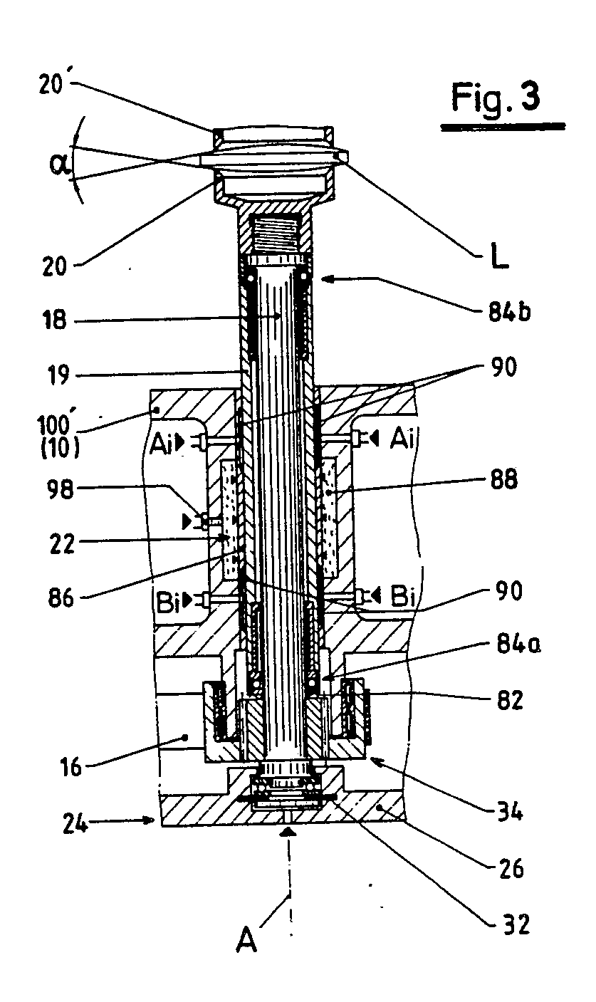
Description
Die vorliegende Erfindung betrifft eine Vorrichtung zum Zentrieren von optischen Linsen für die mechanische Halterung insbesondere beim Randschleifen und Facettieren gemäß dem Oberbegriff von Anspruch 1.The present invention relates to a device for centering optical lenses for mechanical mounting, in particular for edge grinding and faceting, according to the preamble of claim 1.
Gemäß der DE-PS 1 004 516 hat man hierzu die Linse mit hohem Druck zwischen zwei Glocken eingespannt, damit sich ihre Lage nicht mehr selbsttätig ändert. Zum Zentrieren der Linse wurden während des Spannvorganges die Spannglocken durch Ultraschall in Schwingungen versetzt, um die ruhende Reibung zwischen Glocke und Linse in eine niedrigere Gleitreibung umzuwandeln. Dieser Übergang erfolgte jedoch sprunghaft, wodurch häufig Beschädigungen der Linse mit unerwünschtem Materialabtrag auftraten.According to DE-PS 1 004 516, the lens has been clamped at high pressure between two bells so that its position no longer changes automatically. To center the lens, the clamping bells were vibrated by ultrasound during the clamping process in order to convert the static friction between the bell and the lens into a lower sliding friction. However, this transition took place by leaps and bounds, which often resulted in damage to the lens with undesired material removal.
Man hat ferner versucht, die Spannglocken beim Einspannen der Linse mit entgegengesetztem Drehsinn anzutreiben. Auch hierbei besteht ein hohes Beschädigungsrisiko, so daß sich Schleifspuren in Form von in die Linsenoberfläche eingeschnittenen Ringen kaum vermeiden lassen.Attempts have also been made to drive the clamping bells with the opposite direction of rotation when clamping the lens. There is also a high risk of damage here, so that grinding marks in the form of rings cut into the lens surface can hardly be avoided.
In der DE-AS 21 48 102 wurde vorgeschlagen, auf der höhenunveränderlichen Spannglocke einen piezokeramischen Rohrschwinger anzuordnen, der elektrisch über Schwellenwertschalter so gesteuert wird, daß die Spannglocke bei Erreichen eines vorgegebenen Druckes absinkt, wodurch der Schwingungsgenerator abgeschaltet wird. Der Piezoschwinger dient gleichzeitig zum Prüfen des Spanndruckes, dem die Schwingungsamplitude geregelt angepaßt wird. Bei dieser Anordnung sind Elektronik-Unsicherheiten nachteilig. Ferner hat der Schwinger eine nicht unbeachtliche Axialdruckempfindlichkeit. Durch die Druckbelastung beim Einspannen entsteht eine Vorspannung; die Abstützung des Schwingers ist daher problematisch.In DE-AS 21 48 102 it has been proposed to arrange a piezoceramic tube oscillator on the height-adjustable clamping bell, which is controlled electrically via threshold switches so that the clamping bell drops when a predetermined pressure is reached, as a result of which the vibration generator is switched off. The piezo oscillator is also used to check the clamping pressure to which the vibration amplitude is adjusted in a controlled manner. With this arrangement, electronics uncertainties are disadvantageous. Furthermore, the transducer has a not inconsiderable sensitivity to axial pressure. The pressure load during clamping creates a preload; the support of the transducer is therefore problematic.
Aus der DE-OS 31 39 873 ist eine Vorrichtung bekannt, bei der Unregelmäßigkeiten eines Zahnradantriebes ausgenutzt werden, um Relativbewegungen zwischen Linse und Spannglocken zu erzeugen. Als Ausgleichseinrichtung ist ein Waagebalken-Differential in einem Kegelrad-Getriebezug zwischen den beiden Teilen einer zweiteiligen Zentrierspindel und Antriebswelle vorgesehen. Für eine Druckplatte der oberen, axialbeweglichen Spindel ist ein hydraulischer Spannzylinder vorhanden. Infolge der hohen Reibung der Spannspindel in ihrer Gleitlagerung ist jedoch eine feine Regulierung des Einspanndruckes schwer zu realisieren, so daß auch diese Vorrichtung nur begrenzt anwendbar ist.From DE-OS 31 39 873 a device is known in which irregularities of a gear drive are exploited to generate relative movements between the lens and the clamping bell. As a compensation device, a balance beam differential is provided in a bevel gear train between the two parts of a two-part centering spindle and drive shaft. A hydraulic clamping cylinder is available for a pressure plate of the upper, axially movable spindle. Due to the high friction of the clamping spindle in its slide bearing, however, it is difficult to achieve fine regulation of the clamping pressure, so that this device can also be used only to a limited extent.
Aufgabe der Erfindung ist es, unter Überwindung der Nachteile des Standes der Tecknik die zentrische Lagerung und Einspannung optischer Linsen auf wirtschaftlicher Weise so zu verbessern, daß das Einrichten für die Schleifbearbeitung sowie diese selbst in kurzer Zeit, genau und bequem mit geringsmöglicher Druckbeanspruchung der Linse durchgeführt werden kann.The object of the invention is, while overcoming the disadvantages of the prior art of Tecknik, to improve the central mounting and clamping of optical lenses in an economical manner in such a way that the setting up for grinding processing as well as this can be carried out in a short time, precisely and conveniently with minimal pressure on the lens.
Das Hauptmerkmal der Erfindung ist im kennzeichnenden Teil von Anspruch 1 angegeben. Ausgestaltungen sind Gegenstand der Ansprüche 2 bis 10. Indem zumindest für die untere Zentrierspindel ein mit Luft beaufschlagbares Führungslager vorhanden ist, erzielt man erfindungsgemäß in überaus einfacher Weise bei der Axialbewegung der Zentrierspindel einen Übergang zur Gleitreibung, wobei die Reibungskräfte auf etwa ein Zehntel der ruhenden Reibung herabgesetzt werden. Die überaus weich ansprechende Anordnung ermöglicht es, daß der ganze Zentriervorgang während der Phase des leichten Anpressens erfolgt.The main feature of the invention is specified in the characterizing part of claim 1. Refinements are the subject of claims 2 to 10. In that at least for the lower centering spindle an air-bearing guide bearing is available, according to the invention a transition to sliding friction is achieved in an extremely simple manner in the axial movement of the centering spindle, the frictional forces being approximately one tenth of the static friction be reduced. The extremely soft, responsive arrangement enables the entire centering process to take place during the light pressing phase.
Gemäß Anspruch 2 kann auch für die obere Zentrierspindel ein Luftlager vorhanden sein.According to claim 2, an air bearing can also be provided for the upper centering spindle.
Laut Anspruch 3 weist das bzw. jedes Luftlager eine dünne Führungshülse auf, welche die betreffende Zentrierspindel bzw. deren Außenhülse anliegend umschließt und ihrerseits von einem druckbeaufschlagbaren Hohlraum umgeben ist. Diese Anordnung ist konstruktiv einfach und gestattet es, den Klemmdruck nach Bedarf einzustellen bzw. zu regeln um so Spindeln für die Bearbeitung festzuklemmen.According to claim 3, the or each air bearing has a thin guide sleeve, which encloses the centering spindle in question or its outer sleeve and is in turn surrounded by a pressurizable cavity. This arrangement is structurally simple and allows the clamping pressure to be adjusted or regulated as required in order to clamp spindles for machining.
Die Spannlager sind gemäß Anspruch 4 in geschlossenen Kammern des Gehäuses fluchtend angeordnet. Dieses ist dank eines wabenförmigen Aufbaues mit allgemein C-förmiger Ge stalt verwindungssteif, so daß die Spannlager ihre Ausrichtung auch bei hoher Beanspruchung behalten.The radial insert ball bearings are arranged in alignment in closed chambers of the housing. This is thanks to a honeycomb structure with a generally C-shaped Ge stiff torsion-resistant, so that the radial insert bearings keep their orientation even under high loads.
Im oberen Spannlager kann der Druck mittels einer Stelleinrichtung gemäß Anspruch 5 ein- oder nachstellbar sein. Zumindest für das untere Spannlager ist nach Anspruch 6 ein Anschluß zur Druckmittelzufuhr mit steuer- oder einstellbarem Druck vorgesehen. Dadurch lassen sich die gewünschten Druckverhältnisse übersichtlich und genau herstellen.In the upper clamping bearing, the pressure can be set or adjusted by means of an adjusting device. At least for the lower clamping bearing, a connection for supplying pressure medium with controllable or adjustable pressure is provided according to claim 6. This allows the desired pressure conditions to be established clearly and precisely.
Eine wichtige Ausgestaltung der Erfindung, für die selbständiger Schutz in Anspruch genommen wird, besteht gemäß Anspruch 7 darin, daß die einander gegenüberliegenden Luftlager wechselseitig mit höherem und niedrigerem Druck beaufschlagbar sind. Frequenz und Druck der Luftbeaufschlagung können dabei nach Anspruch 8 pneumatisch und/oder elektrisch regel- bzw. einstellbar sein. Die Spannspindel wird also in ihrer Luftlagerung zum Schwingen gebracht, indem zwei sich gegenüberliegende Luftpolster wechselseitig unter erhöhten Druck gesetzt werden. Die Schwingungen können in an sich bekannter Weise mit einem Vibrator erzeugt werden. Durch die über die Luftpolster auf die Spannspindel eingeleitete translatorische Schwingung wird auch die Spannglocke und die Linse in eine translatorische Bewegung versetzt. Da die Linse mit der Spannglocke nicht fest verbunden ist und nur mit dem eigenen Gewicht aufliegt, entstehen durch ihre Massenträgheit kleine Schiebebewegungen zwischen Linse und Spannglocke. Hierdurch wird die ruhende Reibung zu einer gleitenden Reibung und damit auch der Reibungskoeffizient heruntergesetzt. Trifft nun die sich bewegende Linse beim Ausrichten auf die obere Spannglocke werden durch den klei neren Reibungskoeffizienten auch die Ausrichtkräfte wesentlich verringert. Der durch die ruhende Reibung festgelegte minimale Einspannwinkel von 16° kann dadurch wesentlich verkleinert und damit der Bereich der sich selbst zentrierenden Linse vergrößert werden. Speziell können die Luftlager laut Anspruch 9 so gestaltet sein, daß die Innenwand der bzw. jeder Führungshülse Kanäle und/oder Taschen aufweist, insbesondere in Form von je vier Luftpolsterfeldern. In weiterer Spezialisierung sieht Anspruch 10 vor, daß die Kanäle bzw. Taschen als achsparallele und/oder teilringförmige Nuten ausgebildet sind. Die sehr einfache Konstruktion gewährleistet eine genaue Führung mit geringstmöglicher Reibung während der Beaufschlagung mit Druckluft, die auch während der Schleifbearbeitung vorteilhaft ist, um Kühl- und Schmiermittel sowie Materialabrieb von der Spindellagerung fernzuhalten.An important embodiment of the invention, for which independent protection is claimed, according to claim 7, is that the opposing air bearings can be acted upon alternately with higher and lower pressure. The frequency and pressure of the air supply can be pneumatically and / or electrically adjustable or adjustable. The tensioning spindle is therefore made to vibrate in its air bearing by mutually placing two opposing air cushions under increased pressure. The vibrations can be generated in a manner known per se using a vibrator. Due to the translational vibration introduced via the air cushions onto the clamping spindle, the clamping bell and the lens are also set into a translational movement. Since the lens is not firmly connected to the clamping bell and only rests with its own weight, its inertia creates small sliding movements between the lens and the clamping bell. This reduces the static friction to a sliding friction and thus the coefficient of friction. If the moving lens hits the upper clamping bell when aligning it, the small clasp neren friction coefficient also significantly reduced the alignment forces. The minimum clamping angle of 16 ° determined by the static friction can thereby be significantly reduced and thus the area of the self-centering lens can be enlarged. Specifically, the air bearings can be designed so that the inner wall of the or each guide sleeve has channels and / or pockets, in particular in the form of four air cushion fields. In a further specialization,
Weitere Merkmale, Einzelheiten und Vorteile der Erfindung ergeben sich aus dem Wortlaut der Ansprüche sowie aus der folgenden Beschreibung eines Ausführungsbeispiels anhand der Zeichnung. Darin zeigen:
- Fig. 1 eine Axialschnitt-Gesamtansicht einer Zentriervorrichtung,
- Fig. 2 eine vergrößerte Axialschnittansicht einer oberen Zentrierspindel-Lagerung
- Fig. 3 eine vergrößerte Axialschnittansicht einer unteren Zentrierspindel-Lagerung,
- Fig. 4 eine weitere vergrößerte Querschnittsansicht entsprechend der Ebene Ai-Ai in Fig. 3 und
- Fig. 5 eine schematische Darstellung der Druckmittel-Steuerung für die Anordnung gemäß Fig. 3 und 4.
- 1 is an overall axial section view of a centering device,
- Fig. 2 is an enlarged axial sectional view of an upper center spindle bearing
- 3 is an enlarged axial sectional view of a lower centering spindle bearing,
- Fig. 4 is another enlarged cross-sectional view corresponding to the plane A i -A i in Fig. 3 and
- 5 shows a schematic illustration of the pressure medium control for the arrangement according to FIGS. 3 and 4.
Die in Fig. 1 veranschaulichte Vorrichtung hat ein Gehäuse 10 mit einer Lagerung 12 für Antriebswellen 14, 14′, die über Getriebeelemente 16, 16′ auf Zentrierspindeln 18, 18′ wirken, die in Achsrichtung A miteinander fluchten. Sie tragen an ihren freien Enden Spannglocken 20, 20′, zwischen denen eine Linse L ausricht- und einspannbar ist.The device illustrated in Fig. 1 has a
Ein Motor M treibt über einen Riementrieb R und einen Drehmomentteiler 50 die beiden Antriebswellen 14, 14′ synchron an. Die Getriebeelemente 16 wirken auf ein Kupplungsstück 34 am unteren Ende der unteren Zentrierspindel 18, die auch Spannspindel genannt wird. Sie ist mittels einer Spanneinrichtung 24 in Achsrichtung A zustellbar, um eine Linse L auszurichten und während der Schleifbearbeitung mechanisch zu haltern.A motor M drives the two
Die Spanneinrichtung 24 weist ein als Platte ausgebildetes Joch 26 auf, in dem zentrisch ein Membrankolben 32 zur Abstützung des unteren Endes der Spannspindel 18 angeordnet ist. Die Spanneinrichtung 24 befindet sich im unteren, vorragenden Teil 100 des Gehäuses 10, das ein Führungslager 22 für die Spannspindel 18 aufweist. Ein Spannlager 22′ für die obere Zentrierspindel 18′, die auch als Festspindel bezeichnet wird, ist in einem vorragenden Arm 100′ des Gehäuses angeordnet.The
Diese Anordnung ist insbesondere aus Fig. 2 ersichtlich. Man erkennt, daß im Tragteil 100′ des Gehäuses 10 das Spannlager 22′ einen Hohlraum 78 aufweist, der eine Hülse 76 umgibt, welche an der Festspindel 18′ bzw. ihrer Führungshülse 19′ konzentrisch anliegt. Mittels einer als Kolben wirkenden Stellschraube 80 kann der Druck im Hohlraum 78 wahlweise herabgesetzt oder erhöht werden. Durch Lösen der Stellschraube 80 ist es möglich, die Höhenlage der Zentrierspindel 18′ beim Einrichten der Maschine nach Bedarf einzustellen. Sodann wird die obere Zentrierspindel 18′ durch Zudrehen der Stellschraube 80 in ihrer Höhenposition fixiert. Damit ist die obere Spannglocke 20′ höhenunveränderlich festgelegt.This arrangement is particularly evident from FIG. 2. It can be seen that in the support part 100 'of the
Die Zustellung der Linse L, welche auf der unteren Spannglocke 20 ruht, erfolgt nun durch Aufwärtsbewegung der unteren Zentrierspindel 18. Deren Luftlagerung geht aus Fig. 3 hervor. Dieses Luftlager ist im unteren Tragteil 100 des Gehäuses 10 oberhalb der Spanneinrichtung 24 angeordnet. Das Luftlager weist eine Hülse 86 auf, welche die Spannspindel 18 bzw. ihre Führungshülse 19 eng umschließt.The delivery of the lens L, which rests on the
An den Enden der Hülse 86 sind Kanäle 90 vorgesehen, die vorzugsweise achsparallel und/oder teilringförmig angeordnet sind, um insbesondere einander diametral gegenüberliegende Luftpolsterfelder zu bilden. Diese können über Steueröffnungen A und B mit Druckluft beaufschlagt bzw. entlüftet werden, vorzugsweise wechselseitig mit einem pneumatisch oder elektrisch gesteuerten (nicht dargestellten) Vibrator. Durch Frequenz- und Druckregelung können die Schwingungen im Luftlager nach Bedarf eingestellt und optimiert werden. Die leichtgängige Axialbewegung des Zentrierspindel 18 wird dann durch Druckbeaufschlagung des Membrankolbens 32 des Spanneinrichtung 24 bewirkt.At the ends of the
Zum Festspannen der Spannspindel 18 dient ein Spannlager 22, das durch die Hülse 86 und einen die Hülse 86 umgebenden Hohlraum 88 gebildet wird, der über einen Anschluß mit einer Druckmittelzufuhrleitung verbunden ist. Bei Erhöhung des Druckes im Hohlraum 88 verformt sich die Hülse allseitig gleichmäßig und klemmt die Spannspindel exakt axial ausgerichtet fest.A clamping
Die Zentrierspindeln 18, 18′ können einteilig sein. Bevorzugt wird jedoch der Aufbau gemäß Fig. 2 und 3, wonach die Festspindel 18′ eine Führungshülse 19′ hat, die über Stützlager 74a, 74b gegenüber der inneren, eigentlichen Drehspindel 18′ axial und radial abgestützt ist. Entsprechende Stützlager 84a, 84b sind für eine Außenhülse 19 vorgesehen, welche die innere eigentliche Spannspindel 18 umschließt. Im festgeklemmten Zustand sind die beiden Zentrierspindeln ein geringes Stück bedingt durch Wellfedern 82, 82′ axial verschiebbar, so daß der geforderte Einspanndruck eingestellt werden kann.The centering
Sämtliche aus den Ansprüchen, der Beschreibung und der Zeichnung hervorgehenden Merkmale und Vorteile, einschließlich konstruktiver Einzelheiten, räumlicher Anordnungen und Verfahrensschritten, können sowohl für sich als auch in den verschiedenstens Kombinationen erfindungswesentlich sein.All of the features and advantages arising from the claims, the description and the drawing, including structural details, spatial arrangements and method steps, can be essential to the invention both individually and in various combinations.
Claims (10)
Applications Claiming Priority (2)
| Application Number | Priority Date | Filing Date | Title |
|---|---|---|---|
| DE3744116A DE3744116C2 (en) | 1987-12-24 | 1987-12-24 | Machine for centering edge grinding and faceting optical lenses for mechanical mounting |
| DE3744116 | 1987-12-24 |
Publications (3)
| Publication Number | Publication Date |
|---|---|
| EP0322580A2 true EP0322580A2 (en) | 1989-07-05 |
| EP0322580A3 EP0322580A3 (en) | 1990-08-29 |
| EP0322580B1 EP0322580B1 (en) | 1993-05-05 |
Family
ID=6343616
Family Applications (1)
| Application Number | Title | Priority Date | Filing Date |
|---|---|---|---|
| EP88119935A Expired - Lifetime EP0322580B1 (en) | 1987-12-24 | 1988-11-30 | Device for centering optical lenses for mechanical clamping, especially during bevelling and facetting |
Country Status (3)
| Country | Link |
|---|---|
| US (1) | US4941291A (en) |
| EP (1) | EP0322580B1 (en) |
| DE (1) | DE3744116C2 (en) |
Families Citing this family (10)
| Publication number | Priority date | Publication date | Assignee | Title |
|---|---|---|---|---|
| DE4214326A1 (en) * | 1992-04-30 | 1993-11-04 | Wernicke & Co Gmbh | DEVICE FOR EDGE PROCESSING OF EYE GLASSES |
| US6257968B1 (en) | 1998-12-16 | 2001-07-10 | National Optronics, Incorporated | Quick-release lens clamp pad assembly for use in eyeglass lens processing |
| US6243960B1 (en) | 1999-03-16 | 2001-06-12 | National Optronics, Incorporated | Tracer, clamp and object engager for holding and tracing a lens mount of an eyeglass frame, a lens, and/or a lens pattern, to reliably detect a shape thereof even when the shape includes high wrap |
| USD435053S (en) * | 1999-03-16 | 2000-12-12 | National Optronics, Incorporated | Eyeglass frame tracer |
| US6249991B1 (en) | 1999-03-17 | 2001-06-26 | National Optronics, Incorporated | Control system for eyeglass tracer |
| US6283825B1 (en) * | 1999-12-21 | 2001-09-04 | Johnson & Johnson Vision Products, Inc. | Automatic trimmer machine |
| DE10008710C2 (en) | 2000-02-24 | 2002-01-10 | Loh Optikmaschinen Ag | Device for centering clamping of optical lenses for their edge processing |
| US6519861B1 (en) * | 2000-05-04 | 2003-02-18 | Raytheon Company | Mechanical centering apparatus and method |
| DE102004049951A1 (en) * | 2004-10-13 | 2006-04-20 | Schneider Gmbh + Co. Kg | Highly dynamic lens processing machine |
| CN100592125C (en) * | 2006-12-20 | 2010-02-24 | 鸿富锦精密工业(深圳)有限公司 | Lens pressing fixture |
Family Cites Families (14)
| Publication number | Priority date | Publication date | Assignee | Title |
|---|---|---|---|---|
| US2508009A (en) * | 1946-09-11 | 1950-05-16 | Simonds Machine Co Inc | Edging machine |
| BE498786A (en) * | 1950-01-24 | |||
| NL152774A (en) * | 1950-01-24 | |||
| DE1004516B (en) * | 1956-03-02 | 1957-03-14 | Voigtlaender Ag | Method and machine for centering optical lenses |
| US3143382A (en) * | 1961-06-06 | 1964-08-04 | Commissariat Energie Atomique | Aerodynamic bearing |
| US3359045A (en) * | 1966-05-20 | 1967-12-19 | Bendix Corp | Squeeze film bearing |
| US3599377A (en) * | 1968-07-22 | 1971-08-17 | Bausch & Lomb | Lens alignment using gas bearings |
| GB1310135A (en) * | 1970-07-22 | 1973-03-14 | Raphael O P | Method of and apparatus for filling spectacle lenses |
| DE2148102C3 (en) * | 1971-09-27 | 1979-07-05 | Ernst Leitz Wetzlar Gmbh, 6300 Lahn- Wetzlar | Method for centering lenses |
| DK338978A (en) * | 1977-08-02 | 1979-02-03 | Automated Optics | CONTACT LENS AND METHOD AND MACHINE FOR MANUFACTURE OF SUCH LENSES |
| DE2756407A1 (en) * | 1977-12-17 | 1979-06-21 | Prontor Werk Gauthier Gmbh | Lens grinding machine securing spindle bearing system - uses stack of bushes each end, compressed around spindle by adjusting screws |
| DE3139873C2 (en) * | 1981-10-07 | 1983-11-10 | Prontor-Werk Alfred Gauthier Gmbh, 7547 Wildbad | Machine for edge grinding and faceting of optical lenses |
| FR2553323B1 (en) * | 1983-10-18 | 1986-07-25 | Essilor Int | METHOD AND MACHINE FOR BEVELING OR SLOTTING AN OPHTHALMIC LENS |
| DE3526539C1 (en) * | 1985-07-24 | 1986-11-13 | Erwin 7611 Nordrach Junker | Process for precision quick clamping of rotationally symmetrical workpieces and precision quick clamping device for carrying out the process |
-
1987
- 1987-12-24 DE DE3744116A patent/DE3744116C2/en not_active Expired - Fee Related
-
1988
- 1988-11-30 EP EP88119935A patent/EP0322580B1/en not_active Expired - Lifetime
- 1988-12-23 US US07/289,903 patent/US4941291A/en not_active Expired - Fee Related
Also Published As
| Publication number | Publication date |
|---|---|
| DE3744116C2 (en) | 1994-10-13 |
| EP0322580B1 (en) | 1993-05-05 |
| EP0322580A3 (en) | 1990-08-29 |
| DE3744116A1 (en) | 1989-07-06 |
| US4941291A (en) | 1990-07-17 |
Similar Documents
| Publication | Publication Date | Title |
|---|---|---|
| DE3430499C2 (en) | Method and device for lapping or polishing optical workpieces | |
| DE10008710C2 (en) | Device for centering clamping of optical lenses for their edge processing | |
| DE102009006797B4 (en) | Lens processing device | |
| DE19825698B4 (en) | belt sander | |
| EP0322580B1 (en) | Device for centering optical lenses for mechanical clamping, especially during bevelling and facetting | |
| DE3315948C2 (en) | ||
| EP1742762B1 (en) | Device for the production of microstructures | |
| EP0411346A2 (en) | Precision grinding machine for lapping, precision grinding or polishing | |
| EP0278037A1 (en) | Balance centering machine for rotating bodies | |
| EP0322579B1 (en) | Device for centering optical lenses for mechanical clamping, especially during bevelling and facetting | |
| DE2223213B2 (en) | Frame for a measuring or machine tool | |
| DE3533185C2 (en) | ||
| EP0323572B1 (en) | Device for centering optical lenses for mechanical clamping, espcially during bevelling and facetting | |
| DE4306162C2 (en) | Internal taper grinding machine | |
| DE3744117A1 (en) | DEVICE FOR CENTERING OPTICAL LENSES FOR MECHANICAL MOUNTING, IN PARTICULAR WHILE GRINDING AND FACETTING | |
| DE3918365A1 (en) | ULTRA PRECISION GRINDING MACHINE | |
| DE19531506C1 (en) | Grinding machine, in particular cylindrical grinding machine | |
| DE4137071A1 (en) | Guidance system for axial transport of round bars - has housing supporting guide rollers which are divided into pairs around circumference | |
| DE3239720T1 (en) | INTERNAL GRINDING MACHINE | |
| DE3918847C2 (en) | ||
| DE3617790A1 (en) | Ultrasonic machine tool | |
| DE906782C (en) | Device for the drive of vibrating systems with several masses for the fine machining of surfaces | |
| DE3401086A1 (en) | PRECISION BEVEL GRINDERS | |
| DE19543184A1 (en) | Device for mechanical polishing of conical surfaces e.g. optical glass | |
| DE3632403C2 (en) |
Legal Events
| Date | Code | Title | Description |
|---|---|---|---|
| PUAI | Public reference made under article 153(3) epc to a published international application that has entered the european phase |
Free format text: ORIGINAL CODE: 0009012 |
|
| AK | Designated contracting states |
Kind code of ref document: A2 Designated state(s): CH ES FR GB IT LI |
|
| PUAL | Search report despatched |
Free format text: ORIGINAL CODE: 0009013 |
|
| AK | Designated contracting states |
Kind code of ref document: A3 Designated state(s): CH ES FR GB IT LI |
|
| 17P | Request for examination filed |
Effective date: 19901002 |
|
| 17Q | First examination report despatched |
Effective date: 19920318 |
|
| GRAA | (expected) grant |
Free format text: ORIGINAL CODE: 0009210 |
|
| AK | Designated contracting states |
Kind code of ref document: B1 Designated state(s): CH ES FR GB IT LI |
|
| PG25 | Lapsed in a contracting state [announced via postgrant information from national office to epo] |
Ref country code: ES Free format text: THE PATENT HAS BEEN ANNULLED BY A DECISION OF A NATIONAL AUTHORITY Effective date: 19930505 |
|
| ITF | It: translation for a ep patent filed | ||
| ET | Fr: translation filed | ||
| GBT | Gb: translation of ep patent filed (gb section 77(6)(a)/1977) |
Effective date: 19930809 |
|
| PLBE | No opposition filed within time limit |
Free format text: ORIGINAL CODE: 0009261 |
|
| STAA | Information on the status of an ep patent application or granted ep patent |
Free format text: STATUS: NO OPPOSITION FILED WITHIN TIME LIMIT |
|
| 26N | No opposition filed | ||
| PGFP | Annual fee paid to national office [announced via postgrant information from national office to epo] |
Ref country code: GB Payment date: 19941122 Year of fee payment: 7 |
|
| PGFP | Annual fee paid to national office [announced via postgrant information from national office to epo] |
Ref country code: CH Payment date: 19951013 Year of fee payment: 8 |
|
| PGFP | Annual fee paid to national office [announced via postgrant information from national office to epo] |
Ref country code: FR Payment date: 19951020 Year of fee payment: 8 |
|
| PG25 | Lapsed in a contracting state [announced via postgrant information from national office to epo] |
Ref country code: GB Effective date: 19951130 |
|
| GBPC | Gb: european patent ceased through non-payment of renewal fee |
Effective date: 19951130 |
|
| PG25 | Lapsed in a contracting state [announced via postgrant information from national office to epo] |
Ref country code: LI Effective date: 19961130 Ref country code: CH Effective date: 19961130 |
|
| REG | Reference to a national code |
Ref country code: CH Ref legal event code: PL |
|
| PG25 | Lapsed in a contracting state [announced via postgrant information from national office to epo] |
Ref country code: FR Effective date: 19970731 |
|
| REG | Reference to a national code |
Ref country code: FR Ref legal event code: ST |
|
| PG25 | Lapsed in a contracting state [announced via postgrant information from national office to epo] |
Ref country code: IT Free format text: LAPSE BECAUSE OF NON-PAYMENT OF DUE FEES;WARNING: LAPSES OF ITALIAN PATENTS WITH EFFECTIVE DATE BEFORE 2007 MAY HAVE OCCURRED AT ANY TIME BEFORE 2007. THE CORRECT EFFECTIVE DATE MAY BE DIFFERENT FROM THE ONE RECORDED. Effective date: 20051130 |