EP0322588A1 - Dichtung. - Google Patents
Dichtung. Download PDFInfo
- Publication number
- EP0322588A1 EP0322588A1 EP88120021A EP88120021A EP0322588A1 EP 0322588 A1 EP0322588 A1 EP 0322588A1 EP 88120021 A EP88120021 A EP 88120021A EP 88120021 A EP88120021 A EP 88120021A EP 0322588 A1 EP0322588 A1 EP 0322588A1
- Authority
- EP
- European Patent Office
- Prior art keywords
- seal according
- seal
- thin
- shaft pipe
- angle profile
- Prior art date
- Legal status (The legal status is an assumption and is not a legal conclusion. Google has not performed a legal analysis and makes no representation as to the accuracy of the status listed.)
- Granted
Links
- 239000004567 concrete Substances 0.000 claims abstract description 27
- 229920001971 elastomer Polymers 0.000 claims abstract description 3
- 239000000806 elastomer Substances 0.000 claims abstract description 3
- 239000004033 plastic Substances 0.000 claims abstract description 3
- 229920003023 plastic Polymers 0.000 claims abstract description 3
- 239000004568 cement Substances 0.000 claims description 10
- 239000000835 fiber Substances 0.000 claims description 10
- 238000007789 sealing Methods 0.000 claims description 9
- 239000013536 elastomeric material Substances 0.000 claims description 8
- 229920003048 styrene butadiene rubber Polymers 0.000 claims description 8
- 239000000203 mixture Substances 0.000 claims description 5
- 244000043261 Hevea brasiliensis Species 0.000 claims description 3
- 229920003052 natural elastomer Polymers 0.000 claims description 3
- 229920001194 natural rubber Polymers 0.000 claims description 3
- 238000004073 vulcanization Methods 0.000 claims description 3
- 230000007704 transition Effects 0.000 claims description 2
- 239000000463 material Substances 0.000 abstract description 4
- 239000011518 fibre cement Substances 0.000 abstract 1
- 241000196324 Embryophyta Species 0.000 description 3
- 239000000565 sealant Substances 0.000 description 3
- 239000002174 Styrene-butadiene Substances 0.000 description 2
- 239000011083 cement mortar Substances 0.000 description 2
- 238000010276 construction Methods 0.000 description 2
- 238000007373 indentation Methods 0.000 description 2
- 239000011150 reinforced concrete Substances 0.000 description 2
- 229920002430 Fibre-reinforced plastic Polymers 0.000 description 1
- 230000006978 adaptation Effects 0.000 description 1
- 230000006835 compression Effects 0.000 description 1
- 238000007906 compression Methods 0.000 description 1
- 239000011151 fibre-reinforced plastic Substances 0.000 description 1
- 239000011499 joint compound Substances 0.000 description 1
- 239000007788 liquid Substances 0.000 description 1
- 230000004048 modification Effects 0.000 description 1
- 238000012986 modification Methods 0.000 description 1
- 239000004570 mortar (masonry) Substances 0.000 description 1
- 239000007858 starting material Substances 0.000 description 1
- XLYOFNOQVPJJNP-UHFFFAOYSA-N water Substances O XLYOFNOQVPJJNP-UHFFFAOYSA-N 0.000 description 1
Images


Classifications
-
- E—FIXED CONSTRUCTIONS
- E03—WATER SUPPLY; SEWERAGE
- E03F—SEWERS; CESSPOOLS
- E03F3/00—Sewer pipe-line systems
- E03F3/04—Pipes or fittings specially adapted to sewers
-
- F—MECHANICAL ENGINEERING; LIGHTING; HEATING; WEAPONS; BLASTING
- F16—ENGINEERING ELEMENTS AND UNITS; GENERAL MEASURES FOR PRODUCING AND MAINTAINING EFFECTIVE FUNCTIONING OF MACHINES OR INSTALLATIONS; THERMAL INSULATION IN GENERAL
- F16L—PIPES; JOINTS OR FITTINGS FOR PIPES; SUPPORTS FOR PIPES, CABLES OR PROTECTIVE TUBING; MEANS FOR THERMAL INSULATION IN GENERAL
- F16L55/00—Devices or appurtenances for use in, or in connection with, pipes or pipe systems
- F16L55/10—Means for stopping flow in pipes or hoses
- F16L55/115—Caps
Definitions
- the invention relates to a seal for the interface between a thin-walled shaft pipe and a concrete body.
- a concrete body must be placed on the upper end of such a thin-walled shaft pipe, for example made of fiber cement, namely either a horizontal cover plate made of concrete or a concrete ring, namely a cylindrical ring or a cone ring.
- a horizontal concrete cover plate usually contains an annular groove in its underside, in which the upper end of the thin-walled shaft pipe is received.
- the interface between the thin-walled shaft pipe and the relative heavy concrete bodies, the weight of which is of the order of at least 500 kg, must be sealed in order to prevent the liquid from entering and exiting at this point. At the same time, it must be ensured that plant roots cannot grow through the gap between the thin-walled shaft pipe and the concrete body.
- the invention is therefore based on the object of providing a seal for the separating surface between a thin-walled shaft pipe and a concrete body, in which the disadvantages mentioned above do not occur.
- a seal should be proposed that can be easily installed on site.
- the advantages achieved with the invention are based on the use of extruded angle profile cords made of elastomeric material, which are cut to the desired length and then joined together by hot vulcanization to form the finished, ring-shaped seals. It is an elastomeric material based on a vulcanized mixture of a styrene-butadiene rubber and natural rubber (SBR / NR), whereby at least 60% of this mixture consists of styrene-butadiene rubber.
- SBR / NR natural rubber
- the angular profile cords are cut to the desired length taking into account the respective intended use, so that suitable ring seals can be produced for all diameters in question.
- the usual diameters for such thin-walled manhole pipes are between 800 and 1400 mm, the majority of which have a diameter in the range from 1000 to 1200 mm.
- the individual sealing rings which are matched to the desired diameter, are delivered loose and are simply clamped on the construction site by simply pulling them out onto the thin-walled shaft pipe.
- This "clamping pressure" is sufficient for the required internal pressure security of at least 0.1 bar, as specified by the draft to DIN 19549, which prescribes the filling of a pipe shaft up to its upper edge.
- the resistance to external pressures is considerably higher, since the outer lip of the seal is additionally pressed by a bevelled wall, namely either the concrete ring or the groove of the concrete cover plate, and a significantly higher external pressure can be achieved as a result.
- the seal can perform two essential functions; First, the horizontal, about 5 mm thick leg is used to compensate for the slight unevenness in the contact area between the concrete body and the thin-walled shaft pipe, which is inevitable for all materials, so that no point loads can arise. In addition, the highly deformable outer lip is used for additional sealing, whereby it must be taken into account that the horizontal leg alone provides a considerable sealing function due to the weight of the superimposed concrete body. At the same time, it is reliably excluded that plant roots can grow through this gap.
- the horizontal about 5 mm thick leg is used to compensate for the slight unevenness in the contact area between the concrete body and the thin-walled shaft pipe, which is inevitable for all materials, so that no point loads can arise.
- the highly deformable outer lip is used for additional sealing, whereby it must be taken into account that the horizontal leg alone provides a considerable sealing function due to the weight of the superimposed concrete body. At the same time, it is reliably excluded that plant roots can grow through this gap.
- This seal meets both the previous requirements of the ATV and the future DIN standards, which on the one hand require a support between the individual elements made of mortar as compensation for any unevenness and on the other hand a permanently elastic seal against the ingress of water and the growth through root plants .
- the elastomeric material used meets the requirements set out in DIN 4060 for sealing rings made of elastomeric material for pipe connections in drainage channels and pipes.
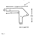
- the seal shown in FIG. 1, generally indicated by the reference numeral 10, is extruded as an endless angle profile cord, cut to the desired length and then assembled into a ring by hot vulcanization.
- An elastomer based on a vulcanized mixture of styrene-butadiene rubber and natural rubber (SBR / NR) with at least 60% styrene-butadiene rubber is used as the starting material.
- This material has the following physical values: ⁇ Hardness: approx. 45 ° shore A Strength: 15 N / mm2 Strain: 650% Compression set at 24 hours at 70 ° C and 40% deformation: 16%
- the seal 10 has the shape of an angle profile with a horizontal leg 12 and a vertical leg 14.
- the vertical leg 14 is provided with a nose-shaped outer lip 16, the beveled upper edge of which is approximately at an angle of 45 ° extends downward from the upper edge of the horizontal leg 12 and merges into the approximately horizontal underside of the outer lip 16 via a rounded edge.
- the horizontal leg 12 has a height of 9 mm, while the vertical leg 14 has a width of 6 mm.
- the overall width of the seal 10 including the outer lip 16 is 42.5 mm and its total height is 22 mm.
- the width between the left edge of the vertical leg 14 and the tip of the outer lip 16 is 17.5 mm, which results in a width of the horizontal leg 12 of 25 mm.
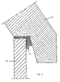
- FIG. 2 shows the upper edge region of a thin-walled shaft pipe 18 made of fiber cement with the seal 10, the legs 12 and 14 of which rest on the upper edge and on the outer surface of the shaft pipe 18.
- a conical concrete ring 20 is placed on the upper end of the shaft pipe 18 and thus on the seal 10, the horizontal leg 12 of the seal 10 is compressed by the weight of the conical concrete ring 20;
- the conical concrete ring 20 has a bevelled, downwardly projecting overhang which compresses the outer lip of the seal 10, as can be seen from a comparison between FIGS. 2 and 3.
- the deformation of the seal 10 in connection with the load caused by the conical concrete ring 20 causes the sealing in this area which meets all requirements.
- FIG. 4 shows the upper edge region of the thin-walled shaft pipe 18 made of fiber cement with the seal 10, the legs 12 and 14 of which rest on the upper edge and on the outer surface of the shaft pipe 18.
- a horizontal cover plate 22 made of reinforced concrete, which is provided on its underside with a circumferential, annular groove 24 with bevelled side walls.
- the width of the groove 24 is somewhat larger than the thickness of the wall of the shaft pipe 18, as can be seen from FIG. 4.
- Fig. 6 shows a modification 10 'of the seal, which differs from the embodiment 10 of FIG. 1 only in that the transition between the outer lip 16 and the vertical leg 14 is designed as a pronounced indentation 36 with an approximately semicircular shape. From its tip, the lower part of the outer lip 16 therefore initially extends parallel to the horizontal leg 12, that is to say at right angles to the vertical leg 14, towards the vertical leg 14 and then on a curved line in the direction of the horizontal leg 12 ends in the semicircular indentation 36 and merges into the wall of the vertical leg 14.
- the semicircular bulge has a radius of approximately 1.5 mm.
Landscapes
- Engineering & Computer Science (AREA)
- General Engineering & Computer Science (AREA)
- Mechanical Engineering (AREA)
- Health & Medical Sciences (AREA)
- Life Sciences & Earth Sciences (AREA)
- Hydrology & Water Resources (AREA)
- Public Health (AREA)
- Water Supply & Treatment (AREA)
- Gasket Seals (AREA)
Abstract
Description
- Die Erfindung betrifft eine Dichtung für die Trennfläche zwischen einem dünnwandigen Schachtrohr und einem Beton-Körper.
- Während sich Beton-Schachtrohre nur mit relativ dicken Wänden fertigen lassen, werden dünnwandige Schachtrohre aus Spezialmaterialien, nämlich Faserzement oder Kunststoff, insbesondere faserverstärktem Kunststoff (GFK), hergestellt.
- Auf das obere Ende eines solchen dünnwandigen Schachtrohres, bspw. aus Faserzement, muß in aller Regel ein Beton-Körper aufgesetzt werden, nämlich entweder eine horizontale Abdeckplatte aus Beton oder ein Beton-Ring, nämlich ein zylindrischer Ring oder ein Konus-Ring. Eine horizontale Abdeckplatte aus Beton enthält in aller Regel in ihrer Unterseite eine ringförmige Nut, in der das obere Ende des dünnwandigem Schachtrohres aufgenommen wird.
- Die Trennfläche zwischen dem dünnwandigem Schachtrohr und dem relativ schweren Beton-Körper, dessen Gewicht in der Größenordnung von mindestens 500 kg liegt, muß abgedichtet werden, um an dieser Stelle den Flüssigkeits-Ein- bzw. Austritt auszuschließen. Gleichzeitig muß gewährleistet sein, daß Pflanzenwurzeln nicht den Spalt zwischen dem dünnwandigen Schachtrohr und dem Beton-Körper durchwachsen können.
- In dem Entwurf zur DIN 19549 wird deshalb die Verwendung spezieller Dichtmittel vorgeschlagen, nämlich Zementmörtel in Verbindung mit Fugenkitt oder einem elastomeren Material. Als Basis-Abdichtung ist dabei die Einfüllung von Zementmörtel in den Spalt zwischen dem Beton-Körper und dem dünnwandigen Schachtrohr erforderlich, so daß sich diese Dichtung nur bei spezieller Ausgestaltung der Trennfläche einsetzen läßt. Außerdem sind die mit der Einbringung dieser Dichtmittel verbundenen Arbeitsgänge aufwendig und lassen sich auf der Baustelle nicht ohne weiteres ausführen. Dies beruht insbesondere auf der Verwendung der zusätzlichen Dichtmittel wie Fugenkitt oder einem elastomeren Material, wie es zur flüssigkeitsdichten Abdichtung erforderlich ist.
- Eine weitere Schwierigkeit liegt darin, daß die auf dem Markt erhältlichen dünnwandigen Schachtrohre, insbesondere Schachtrohre aus Faserzement, große Maßtoleranzen zeigen, wodurch eine entsprechende Anpassung der Abdichtung erforderlich wird.
- Der Erfindung liegt deshalb die Aufgabe zugrunde, eine Dichtung für die Trennfläche zwischen einem dünnwandigen Schachtrohr und einem Beton-Körper zu schaffen, bei der die oben erwähnten Nachteile nicht auftreten. Insbesondere soll eine Dichtung vorgeschlagen werden, die sich auf der Baustelle problemlos montieren läßt.
- Dies wird erfindungsgemäß durch die im kennzeichnenden Teil des Anspruchs 1 angegebenen Merkmale erreicht.
- Zweckmäßige Ausführungsformen werden durch die Merkmale der Unteransprüche definiert.
- Die mit der Erfindung erzielten Vorteile beruhen auf der Verwendung von extrudierten Winkelprofil-Schnüren aus elastomerem Material, die auf die gewünschte Länge geschnitten und dann durch Heißvulkanisation zu den fertigen, ringförmigen Dichtungen zusammengefügt werden. Es handelt sich dabei um ein elastomeren Material auf der Basis eines vulkanisierten Gemisches aus einem Styrol-Butadien-Kautschuk und Naturkautschuk (SBR/NR), wobei mindestens 60 % dieses Gemisches aus Styrol-Butadien-Kautschuk besteht.
- Die Ablängung der Winkelprofil-Schnüre auf die gewünschte Länge erfolgt unter Berücksichtigung des jeweiligen Einsatzzweckes, so daß für alle in Frage kommenden Durchmesser geeignete Ringdichtungen hergestellt werden können. Die üblichen Durchmesser für solche dünnwandigen Schachtrohre liegen zwischen 800 und 1400 mm, wobei der überwiegende Teil einen Durchmesser im Bereich von 1000 bis 1200 mm hat.
- Die einzelnen, auf den gewünschten Durchmesser abgestimmten Dichtungsringe werden lose angeliefert und auf der Baustelle nur einfach durch entsprechendes Ausziehen auf das dünnwandige Schachtrohr aufgespannt. Dieser "Spanndruck" reicht für die erforderliche Innendrucksicherheit von mindestens 0,1 bar aus, wie sie von dem Entwurf zur DIN 19549 festgelegt wird, die das Füllen eines Rohrschachtes bis zu seiner Oberkante vorschreibt.
- Die Widerstandsfähigkeit gegen Außendrücke ist erheblich höher, da die Außenlippe der Dichtung durch eine abgeschrägte Wand, nämlich entweder des Beton-Rings oder der Nut der Beton-Abdeckplatte, zusätzlich angepreßt wird und sich dadurch ein wesentlich höhere Außendruck erzeilen läßt.
- Aufgrund ihrer Form kann die Dichtung zwei wesentliche Funktionen erfüllen; zunächst dient der waagerechte, etwa 5 mm dicke Schenkel dazu, die geringfügigen Unebenheiten im Auflagebereich zwischen dem Beton-Körper und dem dünnwandigen Schachtrohr, die bei allen Materialien zwangläufig vorhanden sind, auszugleichen, so daß keine punktförmigen Auflasten entstehen können. Außerdem dient die stark verformbare Außenlippe zur zusätzlichen Abdichtung, wobei berücksichtigt werden muß, daß der horizontale Schenkel allein aufgrund des Eigengewichtes der aufgelagerten Beton-Körper eine erhebliche Dichtfunktion liefert. Gleichzeitig wird zuverlässig ausgeschlossen, daß Pflanzenwurzeln diesen Spalt durchwachsen können.
- Diese Dichtung genügt sowohl den bisherigen Anforderungen der ATV als auch den zukünftigen DIN-Normen, die zum einen ein Auflager zwischen den einzelnen Elementen aus Mörtel als Ausgleich für etwaige Unebenheiten und zum anderen eine dauerelastische Abdichtung gegen das Eindringen von Wasser sowie die Durchwachsung durch Wurzelpflanzen verlangen.
- Das verwendete elastomere Material entspricht den Anforderungen, die in der DIN 4060 für Dichtungsringe aus elastomeren Material für Rohrverbindungen in Entwässerungskanälen und- Leitungen zusammengestellt sind.
- Die Erfindung wird im folgenden anhand eines Ausführungsbeispieles unter Bezugnahme auf die beiliegenden, schematischen Zeichnungen näher erläutert. Es zeigen
- Fig. 1 einen Querschnitt durch eine Dichtung mit Maßangaben,
- Fig. 2 einen Querschnitt durch den Oberteil einer Wand eines dünnwandigen Schachtrohres aus Faserzement mit der aufgesetzten Dichtung,
- Fig. 3 einen Schnitt durch den Oberteil einer Wand eines dünnwandigen Schachtrohres aus Faserzement mit aufgesetztem, konischem Beton-Ring und verformter Dichtung,
- Fig. 4 einen Querschnitt durch den Oberteil einer Wand eines dünnwandigen Schachtrohrs aus Faserzement mit der aufgesetzten Dichtung und einer darüber angeordneten horizontalen Abdeckplatte aus Stahlbeton,
- Fig. 5 einen Schnitt durch den Oberteil einer Wand eines dünnwandigen Schachtrohres aus Faserzement mit aufgesetzater, horizontaler Abdeckplatte und verformter Dichtung, und
- Fig. 6 einen Querschnitt durch eine abgewandelte Ausführungsform der Dichtung.
- Die aus Figur 1 ersichtliche, allgemein durch das Bezugszeichen 10 angedeutete Dichtung wird als endlose Winkelprofil-Schnur extrudiert, auf die gewünschte Länge geschnitten und dann durch Heißvulkanisation zu einem Ring zusammengefügt. Als Ausgangsmaterial wird ein Elastomer auf der Basis eines vulkanisierten Gemisches von Styrol-Butadien-Kautschuk und Naturkautschuk (SBR/NR) mit mindestens 60 % Styrol-Butadien-Kautschuk eingesetzt.
- Dieses Material hat die folgenden physikalischen Werte:`
Härte: ca. 45° Shore A Festigkeit: 15 N/mm² Dehnung: 650 % Druckverformungsrest bei 24 Std. 70° C und 40 % Verformung: 16 % - Wie man aus Figur 1 entnehmen kann, hat die Dichtung 10 die Form eines Winkelprofils mit einem horizontalen Schenkel 12 und einem vertikalen Schenkel 14. Der vertikale Schenkel 14 ist mit einer nasenförmigen Außenlippe 16 versehen, deren abgeschrägte Oberkante sich etwa unter einem Winkel von 45° von der Oberkante des horizontalen Schenkels 12 nach unten erstreckt und über eine abgerundete Kante in die etwa horizontale Unterseite der Außenlippe 16 übergeht.
- Bei der dargestellten Ausführungsform hat der horizontale Schenkel 12 eine Höhe von 9 mm, während der vertikale Schenkel 14 eine Breite von 6 mm hat.
- Die Gesamtbreite der Dichtung 10 einschließlich der Außenlippe 16 beträgt 42,5 mm und ihre Gesamthöhe 22 mm.
- Die Breite zwischen der linken Kante des vertikalen Schenkels 14 und der Spitze der Außenlippe 16 beträgt 17,5mm, wodurch sich eine Breite des horizontalen Schenkels 12 von 25 mm ergibt.
- Bei Bedarf können jedoch diese Abmessungen noch variiert und an die räum lichen Gegebenheiten der Trennfläche dünnwandigen Schachtrohr/Beton-Ring oder -Platte angepaßt werden.
- Figur 2 zeigt den oberen Randbereich eines dünnwandigen Schachtrohres 18 aus Faserzement mit der Dichtung 10, deren Schenkel 12 bzw. 14 an der Oberkante bzw. an der Außenfläche des Schachtrohres 18 anliegen.
- Wird nun entsprechend Figur 3 ein konischer Beton-Ring 20 auf das obere Ende des Schachtrohrs 18 und damit auf die Dichtung 10 aufgesetzt, so wird der horizontale Schenkel 12 der Dichtung 10 durch das Gewicht des konischen Beton-Rings 20 zusammengedrückt; bei der dargestellten Ausführungsform hat der konische Beton-Ring 20 einen abgeschrägten, nach unten ragenden Überhang, der die Außenlippe der Dichtung 10 zusammendrückt, wie man aus einem Vergleich zwischen den Figuren 2 und 3 erkennt. Die Verformung der Dichtung 10 in Verbindung mit der Belastung durch den konischen Beton-Ring 20 bewirkt die allen Anforderungen genügende Abdichtung in diesem Bereich.
- Wird ein zylindrischer Beton-Ring 20 ohne Überhang verwendet, so wird nur die Unterkante dieses Beton-Rings auf die Dichtung 10 aufgelegt und führt ebenfalls unter Ausnutzung des Auflagedruckes zu einer ausreichenden Abdichtung in diesem Bereich. Die aus Figur 3 ersichtliche Verformung der Außenlippe 16 entfällt hierbei.
- Figur 4 zeigt den oberen Randbereich des dünnwandigen Schachtrohres 18 aus Faserzement mit der Dichtung 10, deren Schenkel 12 bzw. 14 an der Oberkante bzw. an der Außenfläche des Schachtrohres 18 anliegen.
- Über dem Schachtrohr 18 befindet sich eine horizontale Abdeckplatte 22 aus Stahlbeton, die an ihrer Unterseite mit einer umlaufenden, ringförmigen Nut 24 mit abgeschrägten Seitenwänden versehen ist. Die Breite der Nut 24 ist etwas größer als die Dicke der Wand des Schachtrohres 18, wie man aus Figur 4 erkennt.
- Wird nun entsprechend Figur 5 die Abdeckplatte 22 auf das obere Ende des Schachtrohres 18 und damit auf die Dichtung 10 aufgesetzt, so wird der horizontale Schenkel 12 der Dichtung 10 durch das Gewicht der Abdeckplatte 22 zusammengedrückt; gleichzeitig drückt die gemäß der Darstellung in Figur 5 rechte, abgeschrägte Wand der Nut 24 die Außenlippe 16 der Dichtung 10 zusammen, wie man aus einem Vergleich zwischen den Figuren 4 und 5 erkennt. Die Verformung der Dichtung 10 in Verbindung mit der Belastung durch die Abdeckplatte 22 bewirkt die allen Anforderungen genügende Abdichtung in diesem Bereich.
- Fig. 6 zeigt eine Modifikation 10′ der Dichtung, die sich von der Ausführungsform 10 nach Fig. 1 nur dadurch unterscheidet, daß der Übergang zwischen der Außenlippe 16 und dem vertikalen Schenkel 14 als ausgeprägte Einbuchtung 36 mit etwa Halbkreis-Form ausgestaltet ist. Von ihrer Spitze erstreckt sich also der untere Teil der Außenlippe 16 zunächst parallel zum horizontalen Schenkel 12, also im rechten Winkel zum vertikalen Schenkel 14, auf den vertikalen Schenkel 14 zu und dann auf einer gekrümmten Linie in Richtung auf den horizontalen Schenkel 12 zu, die in der halbkreisförmigen Einbuchtung 36 endet und in die Wand des vertikalen Schenkels 14 übergeht. Die halbkreisförmige Ausbuchtung hat einen Radius von etwa 1,5 mm.
- Beim Zusammenpressen dieser Dichtung zwischen dem dünnwandigen Schachtrohr und dem Betonkörper ergibt sich eine Verformung der Außenlippe 16, die zu einer besonders guten Abdichtung führt.
Claims (11)
ein endloses Winkelprofil (10) aus einem elastomeren Material zu einem Ring zusammengefügt ist, und daß die Außenseite des vertikalen Schenkels (14) des Winkelprofils (10) mit einer Außenlippe (16) versehen ist.
Priority Applications (1)
| Application Number | Priority Date | Filing Date | Title |
|---|---|---|---|
| AT88120021T ATE86367T1 (de) | 1987-12-02 | 1988-11-30 | Dichtung. |
Applications Claiming Priority (4)
| Application Number | Priority Date | Filing Date | Title |
|---|---|---|---|
| DE3740861 | 1987-12-02 | ||
| DE3740861 | 1987-12-02 | ||
| DE3806784 | 1988-03-02 | ||
| DE3806784A DE3806784C2 (de) | 1987-12-02 | 1988-03-02 | Abdeckeinrichtung für ein dünnwandiges Schachtrohr |
Publications (2)
| Publication Number | Publication Date |
|---|---|
| EP0322588A1 true EP0322588A1 (de) | 1989-07-05 |
| EP0322588B1 EP0322588B1 (de) | 1993-03-03 |
Family
ID=25862366
Family Applications (1)
| Application Number | Title | Priority Date | Filing Date |
|---|---|---|---|
| EP88120021A Expired - Lifetime EP0322588B1 (de) | 1987-12-02 | 1988-11-30 | Dichtung. |
Country Status (1)
| Country | Link |
|---|---|
| EP (1) | EP0322588B1 (de) |
Cited By (1)
| Publication number | Priority date | Publication date | Assignee | Title |
|---|---|---|---|---|
| EP2312064A1 (de) * | 2009-10-09 | 2011-04-20 | Furnes-Hamjern SCC AS | Verschluss für eine Einstiegsöffnung |
Citations (4)
| Publication number | Priority date | Publication date | Assignee | Title |
|---|---|---|---|---|
| DE1484860A1 (de) * | 1963-05-16 | 1969-05-29 | Vallbo Cement & Byggnadsvaror | Betonring und Vorrichtung fuer dessen Zusammensetzung mit anderen Betonringen |
| DE3406505A1 (de) * | 1984-02-23 | 1985-08-29 | Phoenix Ag, 2100 Hamburg | Steckverbindung fuer muffe und spitzende von beton- und steinzeugrohren |
| DE3539595A1 (de) * | 1985-11-08 | 1987-05-14 | Hanseatische Isoliermittel Gmb | Dichtungsringe mit einlage aus wasserquellbarem kunststoff |
| DE3542427A1 (de) * | 1985-11-30 | 1987-06-04 | Muecher Hermann Gmbh | Muffenrohrverbindung |
Family Cites Families (2)
| Publication number | Priority date | Publication date | Assignee | Title |
|---|---|---|---|---|
| FR2508953A1 (fr) * | 1981-07-06 | 1983-01-07 | Pont A Mousson | Regard de chaussee |
| DE3414180A1 (de) * | 1984-04-14 | 1985-10-24 | Georg Prinzing GmbH & Co KG Betonformen- und Maschinenfabrik, 7902 Blaubeuren | Dichtungseinrichtung fuer aneinanderstossende, zumindest etwa rohrfoermige bauteile, insbesondere fuer betonformteile |
-
1988
- 1988-11-30 EP EP88120021A patent/EP0322588B1/de not_active Expired - Lifetime
Patent Citations (4)
| Publication number | Priority date | Publication date | Assignee | Title |
|---|---|---|---|---|
| DE1484860A1 (de) * | 1963-05-16 | 1969-05-29 | Vallbo Cement & Byggnadsvaror | Betonring und Vorrichtung fuer dessen Zusammensetzung mit anderen Betonringen |
| DE3406505A1 (de) * | 1984-02-23 | 1985-08-29 | Phoenix Ag, 2100 Hamburg | Steckverbindung fuer muffe und spitzende von beton- und steinzeugrohren |
| DE3539595A1 (de) * | 1985-11-08 | 1987-05-14 | Hanseatische Isoliermittel Gmb | Dichtungsringe mit einlage aus wasserquellbarem kunststoff |
| DE3542427A1 (de) * | 1985-11-30 | 1987-06-04 | Muecher Hermann Gmbh | Muffenrohrverbindung |
Cited By (1)
| Publication number | Priority date | Publication date | Assignee | Title |
|---|---|---|---|---|
| EP2312064A1 (de) * | 2009-10-09 | 2011-04-20 | Furnes-Hamjern SCC AS | Verschluss für eine Einstiegsöffnung |
Also Published As
| Publication number | Publication date |
|---|---|
| EP0322588B1 (de) | 1993-03-03 |
Similar Documents
| Publication | Publication Date | Title |
|---|---|---|
| EP0807204B1 (de) | Dichtanordnung für insbesondere tunnelrohrsegmente | |
| DE2518001A1 (de) | Elastische dichtung fuer rohrverbindungen | |
| EP0532459B1 (de) | Muffe zum Verbinden zweier Kunststoffrohre. | |
| EP0213359A1 (de) | Kompensator | |
| EP0634532A2 (de) | Dichtungseinrichtung an einem Bauteil | |
| EP1151220B1 (de) | Rohrkupplung für kunststoffrohre | |
| DE3806784C2 (de) | Abdeckeinrichtung für ein dünnwandiges Schachtrohr | |
| EP0348870B1 (de) | Aus mehreren Stahlbetonfertigteilen zusammengefügter Baukörper in einer Spannbetonbauweise | |
| EP0322588B1 (de) | Dichtung. | |
| DE2630814C3 (de) | Rohrverbindung für unvorbereitete Enden mit einer Dichtungshülse | |
| DE3506104C2 (de) | ||
| EP3927987B1 (de) | Dichtung für grosswälzlager | |
| DE2513982B2 (de) | Rohrdichtung | |
| DE102009036513A1 (de) | Dichtung mit verschiebbarem Dichtungsteil | |
| DE9217222U1 (de) | Abdichtung an zusammensteckbaren Betonfertigteilen | |
| DE8234849U1 (de) | Dichtungsprofil fuer fertigbauteile | |
| AT403392B (de) | Verbindungskörper zum verbinden von zwei im wesentlichen u-förmigen rinnenelementen | |
| DE956806C (de) | Fluessigkeitsbehaelter aus Stahlbeton mit schlaffer oder vorgespannter Bewehrung | |
| CH493769A (de) | Elastischer Dichtungsring | |
| DE2705554A1 (de) | Quetschverschraubung | |
| DE3601756A1 (de) | Dichtungsanordnung fuer bauteile | |
| EP0001046B1 (de) | Anordnung zur Abdichtung von Bauteilen im Hochbau und im Tiefbau, vorzugsweise für Stahlbetontübbinge | |
| EP0347608A1 (de) | Dichtring | |
| EP4703525A1 (de) | Siphonabdichtung | |
| DE2607128B2 (de) | Elastische Profildichtung für axial schließende, symmetrische Kupplungen |
Legal Events
| Date | Code | Title | Description |
|---|---|---|---|
| PUAI | Public reference made under article 153(3) epc to a published international application that has entered the european phase |
Free format text: ORIGINAL CODE: 0009012 |
|
| AK | Designated contracting states |
Kind code of ref document: A1 Designated state(s): AT CH DE ES FR IT LI |
|
| 17P | Request for examination filed |
Effective date: 19891219 |
|
| 17Q | First examination report despatched |
Effective date: 19910104 |
|
| GRAA | (expected) grant |
Free format text: ORIGINAL CODE: 0009210 |
|
| AK | Designated contracting states |
Kind code of ref document: B1 Designated state(s): AT CH DE ES FR IT LI |
|
| REF | Corresponds to: |
Ref document number: 86367 Country of ref document: AT Date of ref document: 19930315 Kind code of ref document: T |
|
| ITF | It: translation for a ep patent filed | ||
| REF | Corresponds to: |
Ref document number: 3878870 Country of ref document: DE Date of ref document: 19930408 |
|
| ET | Fr: translation filed | ||
| PG25 | Lapsed in a contracting state [announced via postgrant information from national office to epo] |
Ref country code: ES Free format text: LAPSE BECAUSE OF FAILURE TO SUBMIT A TRANSLATION OF THE DESCRIPTION OR TO PAY THE FEE WITHIN THE PRESCRIBED TIME-LIMIT Effective date: 19930614 |
|
| RAP2 | Party data changed (patent owner data changed or rights of a patent transferred) |
Owner name: ENSSLE, GERHARD |
|
| REG | Reference to a national code |
Ref country code: FR Ref legal event code: TP |
|
| PLBE | No opposition filed within time limit |
Free format text: ORIGINAL CODE: 0009261 |
|
| STAA | Information on the status of an ep patent application or granted ep patent |
Free format text: STATUS: NO OPPOSITION FILED WITHIN TIME LIMIT |
|
| 26N | No opposition filed | ||
| PGFP | Annual fee paid to national office [announced via postgrant information from national office to epo] |
Ref country code: FR Payment date: 19950116 Year of fee payment: 7 |
|
| PGFP | Annual fee paid to national office [announced via postgrant information from national office to epo] |
Ref country code: CH Payment date: 19950118 Year of fee payment: 7 |
|
| PGFP | Annual fee paid to national office [announced via postgrant information from national office to epo] |
Ref country code: AT Payment date: 19950120 Year of fee payment: 7 |
|
| PGFP | Annual fee paid to national office [announced via postgrant information from national office to epo] |
Ref country code: ES Payment date: 19950130 Year of fee payment: 7 Ref country code: DE Payment date: 19950130 Year of fee payment: 7 |
|
| PG25 | Lapsed in a contracting state [announced via postgrant information from national office to epo] |
Ref country code: LI Effective date: 19951130 Ref country code: CH Effective date: 19951130 Ref country code: AT Effective date: 19951130 |
|
| REG | Reference to a national code |
Ref country code: CH Ref legal event code: PL |
|
| PG25 | Lapsed in a contracting state [announced via postgrant information from national office to epo] |
Ref country code: FR Effective date: 19960731 |
|
| PG25 | Lapsed in a contracting state [announced via postgrant information from national office to epo] |
Ref country code: DE Effective date: 19960801 |
|
| REG | Reference to a national code |
Ref country code: FR Ref legal event code: ST |
|
| PG25 | Lapsed in a contracting state [announced via postgrant information from national office to epo] |
Ref country code: IT Free format text: LAPSE BECAUSE OF NON-PAYMENT OF DUE FEES;WARNING: LAPSES OF ITALIAN PATENTS WITH EFFECTIVE DATE BEFORE 2007 MAY HAVE OCCURRED AT ANY TIME BEFORE 2007. THE CORRECT EFFECTIVE DATE MAY BE DIFFERENT FROM THE ONE RECORDED. Effective date: 20051130 |