EP0322593A2 - Cylindre d'actionnement de freinage à accumulateur à ressort - Google Patents
Cylindre d'actionnement de freinage à accumulateur à ressort Download PDFInfo
- Publication number
- EP0322593A2 EP0322593A2 EP88120107A EP88120107A EP0322593A2 EP 0322593 A2 EP0322593 A2 EP 0322593A2 EP 88120107 A EP88120107 A EP 88120107A EP 88120107 A EP88120107 A EP 88120107A EP 0322593 A2 EP0322593 A2 EP 0322593A2
- Authority
- EP
- European Patent Office
- Prior art keywords
- brake
- spring
- actuating cylinder
- piston
- loaded spring
- Prior art date
- Legal status (The legal status is an assumption and is not a legal conclusion. Google has not performed a legal analysis and makes no representation as to the accuracy of the status listed.)
- Withdrawn
Links
Images
Classifications
-
- B—PERFORMING OPERATIONS; TRANSPORTING
- B60—VEHICLES IN GENERAL
- B60T—VEHICLE BRAKE CONTROL SYSTEMS OR PARTS THEREOF; BRAKE CONTROL SYSTEMS OR PARTS THEREOF, IN GENERAL; ARRANGEMENT OF BRAKING ELEMENTS ON VEHICLES IN GENERAL; PORTABLE DEVICES FOR PREVENTING UNWANTED MOVEMENT OF VEHICLES; VEHICLE MODIFICATIONS TO FACILITATE COOLING OF BRAKES
- B60T17/00—Component parts, details, or accessories of power brake systems not covered by groups B60T8/00, B60T13/00 or B60T15/00, or presenting other characteristic features
- B60T17/08—Brake cylinders other than ultimate actuators
- B60T17/085—Spring loaded brake actuators
Definitions
- the invention relates to a brake actuating cylinder with a spring accumulator, in which the storage spring is connected to the driven head via intermediate members.
- Spring brake cylinders with which the brake is actuated automatically when the operating pressure for normal braking fails have a major disadvantage. Complicated devices must be provided to switch off the spring pressure in the event that the vehicle has to be maneuvered with the spring-loaded brake applied. This is always the case if the brake pressure fails due to a fault in the brake cylinder and not due to the pressure coming from the locomotive.
- the present invention is therefore based on the object to solve the sunken spring accumulator with simple means to the extent that the braking effect is canceled.
- a releasable coupling for example a ball coupling, is arranged between the storage spring and the driven head.
- the advantage of this invention lies in the fact that the clutch can be released without great effort and then the braking effect of the storage spring is already released, so that the vehicle is then maneuverable.
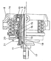
- an example embodiment of the invention is shown on a memory spring brake with automatic play adjustment, the service brake cylinder, not shown, on the with the brake shoes or brake levers connected output head 11 acts when the brake pressure is given in the operating cylinder. Since the operating pressure is also always present in the space 12, the annular piston 13 is held in the position shown in the drawing, in which the storage spring 14 is tensioned by the stop 15 connected to the piston 13. A ball coupling 18 is arranged between an intermediate piece 16 arranged on the rear part of the piston 13 and the pipe 17 connected to the driven head 11.
- This coupling 18 consists of several balls, which partially rest in axially parallel grooves 19 of the piston 13 and the other part on the tube 17 and are held by the closure disc 20 in the position shown in the drawing, in which the balls are a fixed connection of the tube 17 effect with the intermediate piece 16 or the piston 13.
- the closure disc 2o has radially outwardly extending recesses 21 in the same number as the balls, rotation of the closure disc 2o making it possible for the balls to move radially outward from the closed position and thus the connection between the tube 17 and the piston 13 or the intermediate piece 16 is canceled.
- the space 12 is also depressurized and the storage spring 14 presses via the stop 15, the piston 13 or the intermediate piece 16, via the balls 18 on the tube 17, which in turn is not shown here Way (because outside the drawing section) is connected to the output head 11, firmly on the braking surfaces and brakes the vehicle to a standstill.
Landscapes
- Engineering & Computer Science (AREA)
- Transportation (AREA)
- Mechanical Engineering (AREA)
- Braking Arrangements (AREA)
Applications Claiming Priority (2)
| Application Number | Priority Date | Filing Date | Title |
|---|---|---|---|
| DE3744202 | 1987-12-24 | ||
| DE19873744202 DE3744202A1 (de) | 1987-12-24 | 1987-12-24 | Bremsbetaetigungszylinder mit federspeicher |
Publications (2)
| Publication Number | Publication Date |
|---|---|
| EP0322593A2 true EP0322593A2 (fr) | 1989-07-05 |
| EP0322593A3 EP0322593A3 (fr) | 1989-10-04 |
Family
ID=6343678
Family Applications (1)
| Application Number | Title | Priority Date | Filing Date |
|---|---|---|---|
| EP88120107A Withdrawn EP0322593A3 (fr) | 1987-12-24 | 1988-12-02 | Cylindre d'actionnement de freinage à accumulateur à ressort |
Country Status (2)
| Country | Link |
|---|---|
| EP (1) | EP0322593A3 (fr) |
| DE (1) | DE3744202A1 (fr) |
Family Cites Families (8)
| Publication number | Priority date | Publication date | Assignee | Title |
|---|---|---|---|---|
| DE7204850U (de) * | 1973-08-09 | Westinghouse Bremsen Und Apparatebau Gmbh | Mechanische Löseeinrichtung an Federspeicherbremszylindern | |
| DE2542122C3 (de) * | 1975-09-22 | 1979-08-16 | Knorr-Bremse Gmbh, 8000 Muenchen | Mechanische Hilfslöseeinrichtung für Federspeicher- oder Kombizylinder |
| GB1572812A (en) * | 1976-04-02 | 1980-08-06 | Girling Ltd | Brake actuators |
| DE2840836A1 (de) * | 1978-09-20 | 1980-04-03 | Teves Gmbh Alfred | Federspeicher, insbesondere zur bremsbetaetigung |
| IT1126619B (it) * | 1979-12-19 | 1986-05-21 | Magneti Marelli Spa | Cilindro pneu-meccanico di frenatura di veicoli provvisto di meccanismo di sbloccaggio manuale della frenatura meccanica |
| DE3046669A1 (de) * | 1980-12-11 | 1982-07-22 | Wabco Fahrzeugbremsen Gmbh, 3000 Hannover | Mechanische schnell-loeseeinrichtung fuer federspeicher-bremszylinder |
| JPS62227847A (ja) * | 1986-03-28 | 1987-10-06 | Nippon Air Brake Co Ltd | ばねブレ−キシリンダ |
| IT1203566B (it) * | 1986-05-29 | 1989-02-15 | Wabco Westinghouse Spa | Attuatore per freni di veicoli ferroviari e simili |
-
1987
- 1987-12-24 DE DE19873744202 patent/DE3744202A1/de not_active Ceased
-
1988
- 1988-12-02 EP EP88120107A patent/EP0322593A3/fr not_active Withdrawn
Also Published As
| Publication number | Publication date |
|---|---|
| DE3744202A1 (de) | 1989-07-06 |
| EP0322593A3 (fr) | 1989-10-04 |
Similar Documents
| Publication | Publication Date | Title |
|---|---|---|
| DE68906627T2 (de) | Selbstverstaerkende scheibenbremsen. | |
| DE112015004418T5 (de) | Elektrische Feststellbremse mit zwei unabhängigen Aktuatoren | |
| DE2301595A1 (de) | Teilbelagscheibenbremse, insbesondere fuer kraftfahrzeuge | |
| EP0392388A2 (fr) | Cylindre de frein pour véhicules, notamment véhicules ferroviaires | |
| DE1923973A1 (de) | Scheibenbremse | |
| EP2586671A1 (fr) | Frein à étrier fixe avec frein de stationnement électrique | |
| DE2164542B2 (de) | Selbsttätige Nachstellvorrichtung zum Ausgleich des Abriebs der Reibscheibe einer elektromagnetisch lüftbaren Federdruckbremse bzw. -Kupplung | |
| DE2346828A1 (de) | Nachstellvorrichtung fuer bremsen | |
| DE714644C (de) | Lamellenbremse fuer Fahrzeuge, insbesondere Eisenbahnwagen | |
| DE2650490C2 (de) | Pneumatisch oder hydraulisch gesteuerte Scheibenbremse | |
| DE2248143B2 (de) | Bremsbackenaufhängung für Scheibenbremsen | |
| EP0322593A2 (fr) | Cylindre d'actionnement de freinage à accumulateur à ressort | |
| DE2105043A1 (de) | Anpreßeinrichtung für Bremsklötze einer Scheibenbremse | |
| DE2049822C3 (de) | Hydraulisch und mechanisch wirkende Betätigungsvorrichtung für eine Scheibenbremse | |
| DE1750255B2 (de) | Schwimmrahmenscheibenbremse für Kraftfahrzeuge | |
| EP0150052A2 (fr) | Frein à disque à garniture partielle pour véhicules | |
| DE953857C (de) | Lenkkupplung mit Lenkbremse fuer Kraftfahrzeuge, insbesondere Gleiskettenfahrzeuge | |
| AT148221B (de) | Bremse, insbesondere für Schienenfahrzeuge. | |
| DE1201629B (de) | Selbsttaetige, mechanische Nachstellvorrichtung fuer eine Reibungsbremse, insbesondere Scheiben-bremse | |
| AT258148B (de) | Feststellbremse für Kraftfahrzeuge | |
| DE1600126C3 (de) | Teilbelagscheibenbremse | |
| DE3518716C2 (de) | Feststell-Bremseinrichtung für ein Kraftfahrzeug | |
| DE2122505A1 (de) | Scheibenbremse für Kraftfahrzeuge | |
| DE2314719C3 (de) | Teilbelagscheibenbremse, insbesondere für Kraftfahrzeuge | |
| DE1575902C3 (de) | Teilbelagscheibenbremse, insbesondere für Kraftfahrzeuge |
Legal Events
| Date | Code | Title | Description |
|---|---|---|---|
| PUAI | Public reference made under article 153(3) epc to a published international application that has entered the european phase |
Free format text: ORIGINAL CODE: 0009012 |
|
| AK | Designated contracting states |
Kind code of ref document: A2 Designated state(s): AT CH DE ES FR GB IT LI SE |
|
| PUAL | Search report despatched |
Free format text: ORIGINAL CODE: 0009013 |
|
| AK | Designated contracting states |
Kind code of ref document: A3 Designated state(s): AT CH DE ES FR GB IT LI SE |
|
| 17P | Request for examination filed |
Effective date: 19900309 |
|
| 17Q | First examination report despatched |
Effective date: 19901121 |
|
| STAA | Information on the status of an ep patent application or granted ep patent |
Free format text: STATUS: THE APPLICATION IS DEEMED TO BE WITHDRAWN |
|
| 18D | Application deemed to be withdrawn |
Effective date: 19910406 |