EP0322735A2 - Four de boulangerie avec un dispositif d'extraction de la buée - Google Patents
Four de boulangerie avec un dispositif d'extraction de la buée Download PDFInfo
- Publication number
- EP0322735A2 EP0322735A2 EP88121387A EP88121387A EP0322735A2 EP 0322735 A2 EP0322735 A2 EP 0322735A2 EP 88121387 A EP88121387 A EP 88121387A EP 88121387 A EP88121387 A EP 88121387A EP 0322735 A2 EP0322735 A2 EP 0322735A2
- Authority
- EP
- European Patent Office
- Prior art keywords
- oven according
- flow channel
- vapor
- filter
- fat filter
- Prior art date
- Legal status (The legal status is an assumption and is not a legal conclusion. Google has not performed a legal analysis and makes no representation as to the accuracy of the status listed.)
- Granted
Links
Images
Classifications
-
- F—MECHANICAL ENGINEERING; LIGHTING; HEATING; WEAPONS; BLASTING
- F24—HEATING; RANGES; VENTILATING
- F24C—DOMESTIC STOVES OR RANGES ; DETAILS OF DOMESTIC STOVES OR RANGES, OF GENERAL APPLICATION
- F24C15/00—Details
- F24C15/20—Removing cooking fumes
- F24C15/2007—Removing cooking fumes from oven cavities
Definitions
- the innovation relates to an oven according to the preamble of claim 1.
- the innovation is based on the object of designing an oven of the type mentioned in the preamble of protection claim 1 in such a way that the effectiveness and handling of the device for treating the fumes is improved.
- the vapors emerging from the cooking chamber are passed through a large-area grease filter which, because of the large area, has a large absorption capacity for the grease to be separated out and therefore has a long service life.
- a grease filter can consist of paper filter, paper fleece or of expanded metal, plastic or the like and e.g. be mat-like.
- the grease filter preferably extends essentially along the flow channel and is adapted to this flow channel in width and length. In this way, there is a very large filter area, which corresponds at least approximately to the horizontal cross section of the oven housing.
- the grease filter can be easily replaced in the housing section above the cooking chamber, where it can be pulled out from the front of the oven housing in a horizontal arrangement and replaced as a retrofit part.
- the vapors are mixed with cooler secondary air from the surroundings of the cooking space, whereby a mixing ratio is set in which the dew point is as low as possible below the room temperature. Mixing takes place via a fan, which can also serve as a cooling fan for reducing the outside temperature on the oven housing.
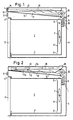
- FIG. 1 denotes an oven muffle, which can be closed by an oven door 2 and which surrounds a cooking space 3.
- the oven muffle 1 is installed in an oven housing 4, which is provided on the front above the oven muffle 1 with controls 5 and corresponding display elements.
- On the back of the oven muffle 1 there is an upwardly directed vapor discharge channel 9, through which the hot and fatty vapors which arise when the oven is in operation can flow upward.
- a cooling fan 10 is arranged in the interior of the oven housing 4 and is driven by a motor, also not shown. While the vapor discharge duct 9 is located on the suction side of the cooling fan 10, a flow duct 11 adjoins the pressure side of the cooling fan 10, delimited by duct walls 12.
- the flow channel 11 is traversed approximately horizontally by a large-area grease filter 13, which is designed in a manner known per se so that it allows a flow through a mixture of vapors and normal ambient air and thereby causes a grease separation.
- the flow conditions are illustrated in the figure by arrows.
- the hot vapors and a certain amount of secondary air 14 from the housing space or from the surroundings of the oven housing 4 is sucked in by the cooling fan 10, mixed and preferably cooled below the dew point of the room temperature, after which this air mixture is pressed against the underside of the large-area grease filter 13, is cleaned there and is discharged to the outside through a front outlet opening 15.
- the blow-out opening 15 has flow guide surfaces 16 inclined upwards, as a result of which the escaping air flow is directed upwards and, for example, does not bother the person standing in front of the oven.
- the flow channel 11 can extend at least approximately over the entire width of the oven housing 4, as a result of which a very large area of the fat filter 13 is obtained.
- the grease filter is designed so that it can be pulled out and exchanged from the front of the oven housing 4 as such or as a detachable component of a support frame, not shown, without the need for tools.
- the amount of secondary air sucked in by the cooling fan 10 and mixed with the vapor 18 can be adjusted or adjusted, for example, by a controllable flap 17.
- the vapor / air mixture is discharged upwards at the rear of the oven housing.
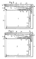
- the flow channel is divided into two substantially horizontal sections 11a and 11b by means of an intermediate wall 19.
- the mixture pressed and cleaned by the cooling fan 10 through the grease filter 13 ' is deflected by essentially 180 ° on the front of the housing and in the second section 11b towards the rear passed where it exits at an air outlet 20 obliquely upwards.
- the function of the intermediate wall 19 can also be performed by the grease filter by appropriate design. In this embodiment, too, it is provided that the grease filter can be removed towards the front.
- the grease filter 13 and 13 divides the flow channel 11 into a lower vapor feed chamber and an upper vapor discharge chamber.
- the grease filters 13 are located on the suction side of the blower 10 in the exemplary embodiments according to FIGS. These exemplary embodiments, longer vapor discharge ducts 9 'are provided, which extend approximately to the middle of the cavity above the furnace muffle 1.
- the fan 10 is arranged above the respective vapor discharge duct 9 'on the back of the oven housing 4.
- the grease filter 13 extends obliquely inclined from a duct wall 20 of the blower 10 to the front outlet opening 15.
- the flow duct 11 is divided into two essentially horizontal sections, namely a section 11c which is delimited by the grease filter 13 downwards and through an intermediate wall 19 upwards and which is on the suction side of the blower 10, and in an upper section 11d which is on the pressure side of the blower 10 and leads to the blow-out opening 15.
Landscapes
- Engineering & Computer Science (AREA)
- Chemical & Material Sciences (AREA)
- Combustion & Propulsion (AREA)
- Mechanical Engineering (AREA)
- General Engineering & Computer Science (AREA)
- Electric Ovens (AREA)
- Ventilation (AREA)
- Filtering Of Dispersed Particles In Gases (AREA)
- Cold Air Circulating Systems And Constructional Details In Refrigerators (AREA)
Applications Claiming Priority (2)
| Application Number | Priority Date | Filing Date | Title |
|---|---|---|---|
| DE8716911U | 1987-12-23 | ||
| DE8716911U DE8716911U1 (de) | 1987-12-23 | 1987-12-23 | Backofen |
Publications (3)
| Publication Number | Publication Date |
|---|---|
| EP0322735A2 true EP0322735A2 (fr) | 1989-07-05 |
| EP0322735A3 EP0322735A3 (en) | 1989-09-20 |
| EP0322735B1 EP0322735B1 (fr) | 1992-03-04 |
Family
ID=6815428
Family Applications (1)
| Application Number | Title | Priority Date | Filing Date |
|---|---|---|---|
| EP88121387A Expired - Lifetime EP0322735B1 (fr) | 1987-12-23 | 1988-12-21 | Four de boulangerie avec un dispositif d'extraction de la buée |
Country Status (2)
| Country | Link |
|---|---|
| EP (1) | EP0322735B1 (fr) |
| DE (2) | DE8716911U1 (fr) |
Cited By (5)
| Publication number | Priority date | Publication date | Assignee | Title |
|---|---|---|---|---|
| FR2797682A1 (fr) * | 1999-08-20 | 2001-02-23 | Aeg Hausgeraete Gmbh | Four de cuisson avec phase d'evacuation et procede de fonctionnement d'un tel four de cuisson |
| EP1156282A1 (fr) * | 2000-05-17 | 2001-11-21 | V-Zug AG | Four de cuisson à dispositif de purge |
| WO2002046662A1 (fr) * | 2000-12-04 | 2002-06-13 | BSH Bosch und Siemens Hausgeräte GmbH | Dispositif de cuisson |
| US20130152913A1 (en) * | 2011-12-16 | 2013-06-20 | J.K. Raghavan | Combination Oven with Catalytic Converter |
| EP3438553A1 (fr) * | 2017-07-31 | 2019-02-06 | Miele & Cie. KG | Appareil de cuisson et procédé |
Families Citing this family (6)
| Publication number | Priority date | Publication date | Assignee | Title |
|---|---|---|---|---|
| IT1234689B (it) * | 1989-03-21 | 1992-05-26 | Zanussi Grandi Impianti Spa | Forno di cottura a convezione forzata |
| DE4322360A1 (de) * | 1993-07-05 | 1995-01-12 | Bosch Siemens Hausgeraete | Einbauherd |
| DE19829651A1 (de) * | 1998-07-02 | 2000-01-05 | Bsh Bosch Siemens Hausgeraete | Herd mit Wrasenfilter |
| DE102005034303B4 (de) * | 2005-07-22 | 2011-04-28 | Electrolux Home Products Corporation N.V. | Garofen |
| DE202015104361U1 (de) * | 2015-08-18 | 2016-11-21 | MKN Maschinenfabrik Kurt Neubauer GmbH & Co. KG | Dunstabzugshaube für ein Gargerät sowie Gargerät mit einer solchen Dunstabzugshaube |
| DE102017117259A1 (de) * | 2017-07-31 | 2019-01-31 | Miele & Cie. Kg | Gargerät und Verfahren |
Family Cites Families (6)
| Publication number | Priority date | Publication date | Assignee | Title |
|---|---|---|---|---|
| US3328560A (en) * | 1964-12-02 | 1967-06-27 | Gen Electric | Recirculating venting system for domestic oven |
| US3514577A (en) * | 1968-12-18 | 1970-05-26 | Gen Electric | Combined expansible broiler oven and kitchen ventilating hood |
| US3587555A (en) * | 1969-05-13 | 1971-06-28 | Jenn Air Corp | Ventilated range |
| GB1452266A (en) * | 1972-10-09 | 1976-10-13 | Still & Sons Ltd W M | Cookers |
| US3858568A (en) * | 1973-12-12 | 1975-01-07 | Raytheon Co | Oven vent hood |
| FR2519121B1 (fr) * | 1981-12-30 | 1986-09-12 | Moulinex Sa | Appareil de cuisine comprenant une table de cuisson, un four et un extracteur des vapeurs de cuisson |
-
1987
- 1987-12-23 DE DE8716911U patent/DE8716911U1/de not_active Expired
-
1988
- 1988-12-21 EP EP88121387A patent/EP0322735B1/fr not_active Expired - Lifetime
- 1988-12-21 DE DE8888121387T patent/DE3868900D1/de not_active Expired - Lifetime
Cited By (7)
| Publication number | Priority date | Publication date | Assignee | Title |
|---|---|---|---|---|
| FR2797682A1 (fr) * | 1999-08-20 | 2001-02-23 | Aeg Hausgeraete Gmbh | Four de cuisson avec phase d'evacuation et procede de fonctionnement d'un tel four de cuisson |
| EP1156282A1 (fr) * | 2000-05-17 | 2001-11-21 | V-Zug AG | Four de cuisson à dispositif de purge |
| WO2002046662A1 (fr) * | 2000-12-04 | 2002-06-13 | BSH Bosch und Siemens Hausgeräte GmbH | Dispositif de cuisson |
| US6817282B2 (en) | 2000-12-04 | 2004-11-16 | Bsh Bosch Und Siemens Hausgeraete Gmbh | Cooker |
| US20130152913A1 (en) * | 2011-12-16 | 2013-06-20 | J.K. Raghavan | Combination Oven with Catalytic Converter |
| US9683747B2 (en) * | 2011-12-16 | 2017-06-20 | Alto-Shaam, Inc. | Combination oven with catalytic converter |
| EP3438553A1 (fr) * | 2017-07-31 | 2019-02-06 | Miele & Cie. KG | Appareil de cuisson et procédé |
Also Published As
| Publication number | Publication date |
|---|---|
| DE8716911U1 (de) | 1988-02-25 |
| EP0322735A3 (en) | 1989-09-20 |
| DE3868900D1 (de) | 1992-04-09 |
| EP0322735B1 (fr) | 1992-03-04 |
Similar Documents
| Publication | Publication Date | Title |
|---|---|---|
| EP1194721B1 (fr) | Dispositif d'aspiration d'air pour poste de travail | |
| DE102008014283B4 (de) | Wrasenabzugsvorrichtung und eine solche umfassende Aufnahmevorrichtung für mindestens eine Speisenzubereitungseinheit | |
| EP0118570B1 (fr) | Hotte d'évacuation à circulation d'air | |
| DE2323596A1 (de) | Verfahren zur filterung von fetthaltigen daempfen und filtereinsatz fuer wrasenabzug | |
| DE10325007A1 (de) | Abzugshaube für einen Küchenherd | |
| DE2206904A1 (de) | Dunstabzugshaube | |
| EP3133350B1 (fr) | Unite combinee comprenant une zone de cuisson et un dispositif d'aspiration de fumees comprenant une unite de filtration | |
| DE102019135258B4 (de) | Kombidämpfer mit wenigstens zwei Gareinheiten und einer Dunstabzugshaube | |
| WO2004090425A2 (fr) | Dispositif servant a aspirer et a fournir de l'air, conçu pour un point de cuisson | |
| EP0322735A2 (fr) | Four de boulangerie avec un dispositif d'extraction de la buée | |
| EP0671591B1 (fr) | Dispositif pour éliminer les buées d'un four | |
| DE102020114719B4 (de) | Kochwrasenabzug | |
| EP0915299B1 (fr) | Unité pour la préparation d'aliments | |
| EP0942235B1 (fr) | Feu de boulanger avec boíte d'aspiration | |
| EP2829808B1 (fr) | Hotte aspirante | |
| DE2531862A1 (de) | Umluft-dunstabzugshaube | |
| EP1094278A2 (fr) | Dispositif d'évacuation des fumées | |
| DE2654170B2 (de) | Dunstabzugshaube zur Anordnung über Küchenherden | |
| EP2677242A1 (fr) | Dispositif de déviation d'air | |
| CH631802A5 (en) | Baking, roasting and grilling oven | |
| DE9416271U1 (de) | Dunstabzugsvorrichtung | |
| CH656942A5 (en) | Baking oven | |
| DE1273162B (de) | Kuechendunstabzugsvorrichtung | |
| DE3545421A1 (de) | In kuechenoberschrank integrierte dunstabzugshaube | |
| DE102010017126A1 (de) | Gargerät |
Legal Events
| Date | Code | Title | Description |
|---|---|---|---|
| PUAI | Public reference made under article 153(3) epc to a published international application that has entered the european phase |
Free format text: ORIGINAL CODE: 0009012 |
|
| AK | Designated contracting states |
Kind code of ref document: A2 Designated state(s): CH DE FR GB IT LI |
|
| PUAL | Search report despatched |
Free format text: ORIGINAL CODE: 0009013 |
|
| RHK1 | Main classification (correction) |
Ipc: F24C 15/20 |
|
| AK | Designated contracting states |
Kind code of ref document: A3 Designated state(s): CH DE FR GB IT LI |
|
| 17P | Request for examination filed |
Effective date: 19891004 |
|
| 17Q | First examination report despatched |
Effective date: 19900417 |
|
| GRAA | (expected) grant |
Free format text: ORIGINAL CODE: 0009210 |
|
| AK | Designated contracting states |
Kind code of ref document: B1 Designated state(s): CH DE FR GB IT LI |
|
| REF | Corresponds to: |
Ref document number: 3868900 Country of ref document: DE Date of ref document: 19920409 |
|
| ITF | It: translation for a ep patent filed | ||
| GBT | Gb: translation of ep patent filed (gb section 77(6)(a)/1977) | ||
| ET | Fr: translation filed | ||
| PLBE | No opposition filed within time limit |
Free format text: ORIGINAL CODE: 0009261 |
|
| STAA | Information on the status of an ep patent application or granted ep patent |
Free format text: STATUS: NO OPPOSITION FILED WITHIN TIME LIMIT |
|
| 26N | No opposition filed | ||
| PGFP | Annual fee paid to national office [announced via postgrant information from national office to epo] |
Ref country code: FR Payment date: 19961113 Year of fee payment: 9 |
|
| PGFP | Annual fee paid to national office [announced via postgrant information from national office to epo] |
Ref country code: GB Payment date: 19961213 Year of fee payment: 9 |
|
| PGFP | Annual fee paid to national office [announced via postgrant information from national office to epo] |
Ref country code: CH Payment date: 19970218 Year of fee payment: 9 |
|
| PG25 | Lapsed in a contracting state [announced via postgrant information from national office to epo] |
Ref country code: GB Free format text: LAPSE BECAUSE OF NON-PAYMENT OF DUE FEES Effective date: 19971221 |
|
| PG25 | Lapsed in a contracting state [announced via postgrant information from national office to epo] |
Ref country code: LI Free format text: LAPSE BECAUSE OF NON-PAYMENT OF DUE FEES Effective date: 19971231 Ref country code: FR Free format text: THE PATENT HAS BEEN ANNULLED BY A DECISION OF A NATIONAL AUTHORITY Effective date: 19971231 Ref country code: CH Free format text: LAPSE BECAUSE OF NON-PAYMENT OF DUE FEES Effective date: 19971231 |
|
| GBPC | Gb: european patent ceased through non-payment of renewal fee |
Effective date: 19971221 |
|
| REG | Reference to a national code |
Ref country code: CH Ref legal event code: PL |
|
| REG | Reference to a national code |
Ref country code: FR Ref legal event code: ST |
|
| PGFP | Annual fee paid to national office [announced via postgrant information from national office to epo] |
Ref country code: DE Payment date: 20021217 Year of fee payment: 15 |
|
| PG25 | Lapsed in a contracting state [announced via postgrant information from national office to epo] |
Ref country code: DE Free format text: LAPSE BECAUSE OF NON-PAYMENT OF DUE FEES Effective date: 20040701 |
|
| PG25 | Lapsed in a contracting state [announced via postgrant information from national office to epo] |
Ref country code: IT Free format text: LAPSE BECAUSE OF NON-PAYMENT OF DUE FEES;WARNING: LAPSES OF ITALIAN PATENTS WITH EFFECTIVE DATE BEFORE 2007 MAY HAVE OCCURRED AT ANY TIME BEFORE 2007. THE CORRECT EFFECTIVE DATE MAY BE DIFFERENT FROM THE ONE RECORDED. Effective date: 20051221 |