EP0323039A2 - Air cooling system in an internal combustion engine - Google Patents
Air cooling system in an internal combustion engine Download PDFInfo
- Publication number
- EP0323039A2 EP0323039A2 EP88311384A EP88311384A EP0323039A2 EP 0323039 A2 EP0323039 A2 EP 0323039A2 EP 88311384 A EP88311384 A EP 88311384A EP 88311384 A EP88311384 A EP 88311384A EP 0323039 A2 EP0323039 A2 EP 0323039A2
- Authority
- EP
- European Patent Office
- Prior art keywords
- exhaust gas
- air
- gas stream
- internal combustion
- acceleration unit
- Prior art date
- Legal status (The legal status is an assumption and is not a legal conclusion. Google has not performed a legal analysis and makes no representation as to the accuracy of the status listed.)
- Granted
Links
Images



Classifications
-
- F—MECHANICAL ENGINEERING; LIGHTING; HEATING; WEAPONS; BLASTING
- F01—MACHINES OR ENGINES IN GENERAL; ENGINE PLANTS IN GENERAL; STEAM ENGINES
- F01N—GAS-FLOW SILENCERS OR EXHAUST APPARATUS FOR MACHINES OR ENGINES IN GENERAL; GAS-FLOW SILENCERS OR EXHAUST APPARATUS FOR INTERNAL-COMBUSTION ENGINES
- F01N9/00—Electrical control of exhaust gas treating apparatus
-
- F—MECHANICAL ENGINEERING; LIGHTING; HEATING; WEAPONS; BLASTING
- F01—MACHINES OR ENGINES IN GENERAL; ENGINE PLANTS IN GENERAL; STEAM ENGINES
- F01P—COOLING OF MACHINES OR ENGINES IN GENERAL; COOLING OF INTERNAL-COMBUSTION ENGINES
- F01P5/00—Pumping cooling-air or liquid coolants
- F01P5/02—Pumping cooling-air; Arrangements of cooling-air pumps, e.g. fans or blowers
- F01P5/08—Use of engine exhaust gases for pumping cooling-air
-
- F—MECHANICAL ENGINEERING; LIGHTING; HEATING; WEAPONS; BLASTING
- F01—MACHINES OR ENGINES IN GENERAL; ENGINE PLANTS IN GENERAL; STEAM ENGINES
- F01N—GAS-FLOW SILENCERS OR EXHAUST APPARATUS FOR MACHINES OR ENGINES IN GENERAL; GAS-FLOW SILENCERS OR EXHAUST APPARATUS FOR INTERNAL-COMBUSTION ENGINES
- F01N1/00—Silencing apparatus characterised by method of silencing
- F01N1/08—Silencing apparatus characterised by method of silencing by reducing exhaust energy by throttling or whirling
-
- F—MECHANICAL ENGINEERING; LIGHTING; HEATING; WEAPONS; BLASTING
- F01—MACHINES OR ENGINES IN GENERAL; ENGINE PLANTS IN GENERAL; STEAM ENGINES
- F01N—GAS-FLOW SILENCERS OR EXHAUST APPARATUS FOR MACHINES OR ENGINES IN GENERAL; GAS-FLOW SILENCERS OR EXHAUST APPARATUS FOR INTERNAL-COMBUSTION ENGINES
- F01N1/00—Silencing apparatus characterised by method of silencing
- F01N1/08—Silencing apparatus characterised by method of silencing by reducing exhaust energy by throttling or whirling
- F01N1/085—Silencing apparatus characterised by method of silencing by reducing exhaust energy by throttling or whirling throttling exhaust gas flow using a central core in a flow passage
-
- F—MECHANICAL ENGINEERING; LIGHTING; HEATING; WEAPONS; BLASTING
- F01—MACHINES OR ENGINES IN GENERAL; ENGINE PLANTS IN GENERAL; STEAM ENGINES
- F01N—GAS-FLOW SILENCERS OR EXHAUST APPARATUS FOR MACHINES OR ENGINES IN GENERAL; GAS-FLOW SILENCERS OR EXHAUST APPARATUS FOR INTERNAL-COMBUSTION ENGINES
- F01N5/00—Exhaust or silencing apparatus combined or associated with devices profiting by exhaust energy
- F01N5/04—Exhaust or silencing apparatus combined or associated with devices profiting by exhaust energy the devices using kinetic energy
-
- F—MECHANICAL ENGINEERING; LIGHTING; HEATING; WEAPONS; BLASTING
- F02—COMBUSTION ENGINES; HOT-GAS OR COMBUSTION-PRODUCT ENGINE PLANTS
- F02B—INTERNAL-COMBUSTION PISTON ENGINES; COMBUSTION ENGINES IN GENERAL
- F02B1/00—Engines characterised by fuel-air mixture compression
- F02B1/02—Engines characterised by fuel-air mixture compression with positive ignition
- F02B1/04—Engines characterised by fuel-air mixture compression with positive ignition with fuel-air mixture admission into cylinder
-
- F—MECHANICAL ENGINEERING; LIGHTING; HEATING; WEAPONS; BLASTING
- F02—COMBUSTION ENGINES; HOT-GAS OR COMBUSTION-PRODUCT ENGINE PLANTS
- F02B—INTERNAL-COMBUSTION PISTON ENGINES; COMBUSTION ENGINES IN GENERAL
- F02B75/00—Other engines
- F02B75/02—Engines characterised by their cycles, e.g. six-stroke
- F02B2075/022—Engines characterised by their cycles, e.g. six-stroke having less than six strokes per cycle
- F02B2075/027—Engines characterised by their cycles, e.g. six-stroke having less than six strokes per cycle four
-
- F—MECHANICAL ENGINEERING; LIGHTING; HEATING; WEAPONS; BLASTING
- F02—COMBUSTION ENGINES; HOT-GAS OR COMBUSTION-PRODUCT ENGINE PLANTS
- F02B—INTERNAL-COMBUSTION PISTON ENGINES; COMBUSTION ENGINES IN GENERAL
- F02B3/00—Engines characterised by air compression and subsequent fuel addition
- F02B3/06—Engines characterised by air compression and subsequent fuel addition with compression ignition
-
- Y—GENERAL TAGGING OF NEW TECHNOLOGICAL DEVELOPMENTS; GENERAL TAGGING OF CROSS-SECTIONAL TECHNOLOGIES SPANNING OVER SEVERAL SECTIONS OF THE IPC; TECHNICAL SUBJECTS COVERED BY FORMER USPC CROSS-REFERENCE ART COLLECTIONS [XRACs] AND DIGESTS
- Y02—TECHNOLOGIES OR APPLICATIONS FOR MITIGATION OR ADAPTATION AGAINST CLIMATE CHANGE
- Y02T—CLIMATE CHANGE MITIGATION TECHNOLOGIES RELATED TO TRANSPORTATION
- Y02T10/00—Road transport of goods or passengers
- Y02T10/10—Internal combustion engine [ICE] based vehicles
- Y02T10/12—Improving ICE efficiencies
Definitions
- This invention relates to an accelerator for accelerating an exhaust gas stream in an internal combustion engine and an air cooling mechanism for forcibly cooling an inner core directly with suction atmospheric air by means of said accelerator.
- Gas produced by combustion in an internal combustion engine is exhausted into the atmosphere through an exhaust gas conduit.
- the velocity of an exhaust gas stream is high over a sonic velocity, such as 650 to 800 m/sec. immediately after the exhaust gas is exhausted from a cylinder, but rapidly attenuated and stabilized at approx. 200 m/sec.
- a catalyst, a silencer and the like are provided in necessity for an exhaust gas pollution remedy and a noise countermeasure, and an exhaust gas stream is exhausted by thereby decelerating the velocity.
- the present inventor has studies to except solutions of the above-described problems and further several problems of an internal combustion engine in terms of controlling an exhaust gas stream.
- the several problems include an instability of rotation of a high speed engine for a conventional automobile at the time of low speed rotation, exhaust of high temperature exhaust gas stream, a decrease in charging efficiency due to the resistance of a catalyst and a silencer, and a remarkable increase in exhaust of detrimental components at the time of real traveling even if the exhaust of the detriments is restricted at an idling time, etc.
- the suitable method contains, for example, a contrivance of directly accelerating an exhaust gas stream without depending upon a motor drive for consuming an engine output or an elimination of a decrease again in the velocity of the accelerated exhaust gas stream.
- An internal combustion engine which employs an air cooling type is known, and frequently used for small size and small heat generation.
- a liquid cooling type engine using coolant such as water
- the boiling temperature of the liquid is lower than the heating temperature of the engine. Since the heating temperature of the engine has small difference from the ambient temperature when the engine is rotated, if a load is increased or the engine is continuously rotated at a high speed, the coolant immediately arrives at the boiling point to cause the engine to feasibly overheat.
- Other disadvantages of the liquid cooling type engine include a complicated structure, necessity of sealing for preventing liquid from leaking at temperature change of approx. 100 degrees C, necessity of managing coolant quantity, and components to be complicated for maintenance.
- means for lowering the coolant liquid temperature in the liquid cooling type engine is a radiator, in which heat exchange from the air occurs.
- the mean atmospheric temperature is approx. 20°C, or approx. 50°C under the most severe condition. This is much lower than the boiling point of the coolant in the conventional cooling type, and there is a possibility of infinitive availability.
- the present inventor has advanced studies and developments of technique from this standpoint by air cooling directly the inner core of an engine.
- the present invention has discovered in the progress of studies and tests for the suction type forcibly air cooling system of the present invention the fact that, in order to efficiently and effectively form the negative pressure, the mounting position of a negative pressure generator, the structure of the negative pressure generator and the process of negative pressure air stream are important, thereby necessarily enhancing remarkably the velocity of negative pressure air stream. More specifically, suction energy is extremely increased by accelerating extremely the negative pressure air stream. According to the experiments, it is accelerated to the stage of obtaining a velocity exceeding a sonic velocity at the time of operating an engine at a high speed.
- a primary object of this invention is to provide an exhaust gas stream accelerator for an internal combustion engine in which the exhaust gas stream is self-accelerated to accelerate the exhaust gas stream at a velocity faster than a normal velocity, thereby reducing a back pressure, controlling a load to solve the above-mentioned various problems.
- Another object of this invention is to provide a suction type air cooling mechanism for sufficiently forcibly air cooling by negative pressure air stream accelerated at a high velocity by using said accelerator.
- an exhaust gas stream accelerator for an internal combustion engine having an exhaust gas conduit for exhausting exhaust gas stream exhausted from the combustion chamber of the internal combustion engine into the atmosphere comprising one or more stages of acceleration units for self-accelerating the velocity of an exhaust gas stream at the downstream of the exhaust gas conduit applied with resistance of f the exhaust gas conduit itself and/or load resistance of a catalyst, a silencer or the like provided in the exhaust gas conduit.
- the exhaust gas conduit includes an exhaust pipe called in an automotive engine, an acceleration unit provided at the lowermost downstream of the exhaust system to self-accelerate the exhaust gas stream by passing it through the acceleration unit even without aid of power.
- the other object of the invention can be also achieved by a suction type air cooling mechanism for an internal combustion engine composed to air cool an engine body by introducing the atmospheric air sucked by a negative pressure generator provided in an exhaust gas system to the engine body comprising at least one stage of acceleration unit reduced in its passage sectional area and provided in the flowing direction of exhaust gas stream in the exhaust gas system, an air inlet port provided in the vicinity of each acceleration unit, in such a manner that the rear volume from the acceleration unit is increased, and a duct provided in a casing covered thereon to be connected at the rear end thereof to the casing for exhausting the engine cooled atmospheric air.
- the air inlet is provided at the rear of one or more stages of acceleration units, and it is most preferable to uniformly provide a plurality of openings circumferentially.
- the negative pressure generator is provided in the engine exhaust gas system, and positioned generally at the downstream having small rear resistance, and at the downstream from a muffler, if the muffler is provided, and particularly at the lowermost downstream at the belt. This is because it prevents the accelerated negative pressure air stream from again receiving resistance by the muffler to decelerate the velocity of the negative air stream to decrease the suction energy.
- the negative pressure generators are composed of multiple stages. For example, in case of three stages, first, second and third negative pressure generators are sequentially disposed longitudinally from the upstream side. Since the volume of the suction atmospheric air introduced through the duct is added immediately after the respective acceleration units, the volumes of the first acceleration unit is larger than the second acceleration unit, the third acceleration unit is sequentially larger in volume than the second acceleration unit, thereby setting a plurality of stages of suction acceleration streams.
- the acceleration units described above are formed by providing throats in the exhaust gas passage.
- the throat may be formed, for example, in a venturi tube structure in which the sectional area of the exhaust gas stream passage is altered, a structure in which the passage sectional area is not altered, but acceleration is generated in accordance with the shape of an intermediate, or a combination of them.
- One or more throats are formed along the exhaust gas stream.
- Fig. 1 shows an internal combustion engine having an accelerator of this invention.
- Numeral 1 denotes an internal combustion engine body
- numeral 2 denotes an exhaust gas conduit
- numeral 3 denotes an acceleration unit in which loads 4, such as a catalyst 41, a silencer 42 are provided in the exhaust gas conduit 2, and provided at the rear of the loads. It avoids the defect that, when the accelerator is disposed before the load of an intermediate stream, accelerated exhaust gas stream is again decelerated by the loads.
- the accelerator is schematically shown in Fig. 2, and selected in various structures as shown in detail in Figs. 3 to 7
- First type is an acceleration unit 3 having a sole throat 5 in a direction of an exhaust gas stream line, the throat 5 is gradually reduced in the sectional area of an exhaust gas passage 6, and formed of a throttle tube 7 for converting kinetic energy of the exhaust gas stream into a velocity.
- a structure for sucking in vacuum the air is also formed in the acceleration unit 3
- air inlets 81, 82, 83 are formed immediately after first, second and third throats 51, 52, 53.
- the throats are increased in volumes sequentially by double, and so formed that the exhaust gas stream is exhausted smoothly together with the sucked air stream from a tail tube 9.
- the inlets 81 to 83 are preferably formed with an angle ⁇ so as to accelerate the introduction of the air.
- Numeral 10 denotes a casing.
- the air stream introduced by means of the negative pressure may be utilized for various utilities.
- detrimental components such as CO, NOx contained in the exhaust gas can be significantly reduced. This is considered from the result that vigorous turbulence is generated by the collision so that the components in the exhaust gas are chemically reacted with the air. In this case, it is recognized a phenomenon that a large quantity of water is produced.
- the other utility includes the use of suction air stream, for example, to air cool an engine or to drive a turbo-supercharger.
- An acceleration unit 3 shown in Fig. 4 is of type in which suitable number of acceleration units 11 of blade sectional shape are interposed in parallel with the exhaust gas stream line and a plurality of throats 131, 132,.. are formed in a passage 12. In this case, the sectional area of passing the exhaust gas stream of the passage is reduced, but the acceleration by the blade type acceleration unit 11 utilizes a phenomenon that the exhaust gas is passed along the surface of the acceleration unit to be accelerated.
- the blade sectional shape may include a high speed type, or a type adapted for acceleration, but, in order to avoid the adverse influence of generating a shock wave, the acceleration units 11 may be optionally disposed by longitudinally displacing them.
- An acceleration unit duct 14 for forming a passage is formed in a circular section, or in a rectangular section as shown in Fig. 5, and an acceleration curved surface 15 is formed on the inner wall (Fig. 2).
- Figs. 6 to 8 show the type in which an acceleration unit 3 is composed in combination with a throttle tube 17 and a spinning acceleration unit 16, a throat 18 is formed between the throttle tube 17 and the acceleration unit 16, and the acceleration unit 16 is set to the center by a supporting blade 19.
- the acceleration units 3 described above may be provided in multiple stages in a flowing direction.
- numeral 20 denotes a combustion chamber
- numeral 21 denotes a suction port
- numeral 22 denotes an exhaust port
- numeral 23 denotes a cylinder
- numeral 24 denotes a jacket.
- coolant liquid is circulated.
- Numeral 25 denotes a piston.
- the accelerator of this invention When the accelerator of this invention is associated in the exhaust gas conduit 2 of the internal combustion engine, the exhaust gas stream exhausted from the combustion engine is remarkably accelerated by the passage through throats 5 and 11 in the acceleration unit 3 to again recover the velocity of the exhaust gas stream decelerated by the resistances of the loads, such as a catalyst, a silencer provided in the exhaust gas system and the exhaust gas conduit itself, and further accelerated.
- the loads such as a catalyst, a silencer provided in the exhaust gas system and the exhaust gas conduit itself
- the exhaust gas stream accelerator of this invention performs an effect of remarkably accelerating the velocity of the exhaust gas stream, it can stably accelerate the exhaust of the exhaust gas into the atmosphere, stabilizes the operation by applying a torque at the time of low speed rotation to prevent the back pressure from becoming excessive, thereby improving its charging efficiency, almost eliminates detrimental components of the exhaust gas by the collision with the air at high speed, thereby remarkably improving the performance of the internal combustion engine.
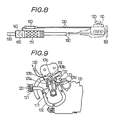
- numeral 110 denotes an engine body in which the air cooling mechanism of this invention is executed
- numeral 120 denotes an atmospheric air inlet
- numeral 130 denotes a duct for discharging heated air after heat exchanging
- numeral 140 denotes a negative pressure generator, provided at the downstream of the muffler 151 of an exhaust gas conduit 150.
- Numeral 160 denotes a reverse silencer.
- An air jacket 101a, 101b, 101c, 101d,.., are so provided in the engine body 110 as to surrounded the periphery of heat generators, such as a cylinder 111, a piston 112, a cylinder head 113, etc.
- the air fed from the atmospheric air inlet 120 and purified by a filter 121 is introduced through an air inlet tube 122 and one or more ports 123 into all air jackets 101a,...
- a conduct, i.e., an air discharge duct 130 for discharging the air after heat exchanging is connected to the air jackets 101a, ....
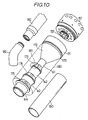
- the accelerator is shown in Figs. 10 to 12, and has an acceleration cylinder 170 and a casing 180.
- the acceleration cylinder 170 has a tapered tube 172 throttled in diameter at minimum from the large diameter section of the front end connected by a connector 171 to the muffler 151, a first acceleration unit 141, a first air inlet 173, a second acceleration unit 142, a second air inlet 172, a third acceleration unit 143, a third air inlet 175, and a connector 144 disposed longitudinally sequentially, and a tail tube 190 connected at the tail.
- Numeral 181 denotes an opening formed at the casing 180, connected through a connector pipe 182 to a reverse flow preventing silencer 160.
- the volume V1 of the first acceleration unit 141 is set to the necessary volume to throttle the exhaust gas stream velocity to the minimum by a tapered tube 172 to obtain a first acceleration stream.
- the coefficients A, B may, of course, take another arbitrary numeric values.
- the inner diameter of the tail tube 190 is larger than that of the third acceleration unit 143.
- the first to third air inlets 173, 174, 174 are preferably formed with forwarding angle ⁇ , which is large than "0" to be less than 90°, and preferably 10 to 30°.
- the numbers of the openings and the diameter of the opening of the inlets 173 to 175 are so set as to introduce the external air stream from the air discharge duct 130 at a high speed.
- the muffler 151 and the reverse silencer 160 have a type in which triple and single bypass passages are provided at the periphery of the main passage to expansion silence it.
- the reverse silencer 160 has a check valve 161 for preventing the reverse flow of exhaust gas sound from the negative pressure generator 140 from occurring and momentary pressure from pulsating.
- Numeral 152 denotes a low speed torque generator provided at the rear end of the muffler 151 to throttle the exhaust gas passage in the muffler 151 to obtain a torque at a low speed.
- a cooling fan 153 is originally eliminated, but if it is provided, it serves to cool the exterior of the engine.
- the negative pressure generator 140 quickly accelerates at first stage in the first acceleration unit 141 continued to the tapered tube 172, then sequentially accelerates at high speed over three stages in the second and third acceleration units 142, 143. Accordingly, it is accelerated at high speed exceeding sonic velocity in the state accelerated at the maximum to increase the exhaust gas flow rate, and the negative pressure arrives at approx. 3 bar. More specifically, in case of experiments, an energy of penetrating 40 to 80 sheets of tissue paper is obtained at the connection port of the connector pipe 182 to the reverse silencer 160. This strong suction action is obtained by highly accelerating by utilizing the exhaust gas stream.
- the purpose of accelerating the negative air stream in the suction type air cooling mechanism to an ultrahigh speed is performed to form a necessary negative pressure by the high speed air stream. Accordingly, the atmospheric air suction effect is remarkably enhanced. As a result, the cooled air is remarkably smoothly exhausted, low temperature cooling air can be efficiently introduced against it to prove the cooling effect by this invention.
- the negative pressure necessary to suck the cooling air is obtained by utilizing the exhaust gas stream to improve the efficiency of the entire engine at the maximum. Because the decrease in the utility efficiency of the engine output by producing the power and the rotary force from the engine to rotate the fan and forming the negative pressure is eliminated.
- the exhaust gas energy is utilized to extremely accelerate the exhaust gas stream in the acceleration unit to form the negative pressure energy. Accordingly, if the formation of the negative pressure is conducted by the rotation output of the engine, it is affected by the rotation of the engine, but the exhaust energy at the time of operating the loads is converted to the suction energy as it is by the negative pressure generator, and air cooling effect responsive to the actual operating state can be obtained. Further, the exhaust gas temperature is extremely effectively lowered by this invention, resulting in mixture of large quantity of the air, thereby remarkably reducing the detrimental substance concentration in the exhaust gas.
Landscapes
- Engineering & Computer Science (AREA)
- Chemical & Material Sciences (AREA)
- Combustion & Propulsion (AREA)
- Mechanical Engineering (AREA)
- General Engineering & Computer Science (AREA)
- Exhaust Silencers (AREA)
- Exhaust Gas After Treatment (AREA)
Abstract
Description
- This invention relates to an accelerator for accelerating an exhaust gas stream in an internal combustion engine and an air cooling mechanism for forcibly cooling an inner core directly with suction atmospheric air by means of said accelerator.
- Gas produced by combustion in an internal combustion engine is exhausted into the atmosphere through an exhaust gas conduit. The velocity of an exhaust gas stream is high over a sonic velocity, such as 650 to 800 m/sec. immediately after the exhaust gas is exhausted from a cylinder, but rapidly attenuated and stabilized at approx. 200 m/sec.
- In a gasoline engine for an automobile, for example, a catalyst, a silencer and the like are provided in necessity for an exhaust gas pollution remedy and a noise countermeasure, and an exhaust gas stream is exhausted by thereby decelerating the velocity.
- As a result, a back pressure becomes excessive in an exhaust gas conduit, resulting in a decrease in an engine efficiency, a rise in exhaust gas temperature, thereby damaging the exhaust gas conduit or affecting adverse influence of high temperature to the periphery of an exhaust section.
- The present inventor has studies to except solutions of the above-described problems and further several problems of an internal combustion engine in terms of controlling an exhaust gas stream. The several problems include an instability of rotation of a high speed engine for a conventional automobile at the time of low speed rotation, exhaust of high temperature exhaust gas stream, a decrease in charging efficiency due to the resistance of a catalyst and a silencer, and a remarkable increase in exhaust of detrimental components at the time of real traveling even if the exhaust of the detriments is restricted at an idling time, etc.
- As a result of the above-mentioned studies, it has been confirmed that significant effects are presented in various fields by accelerating the velocity of exhaust gas by a suitable method. The suitable method contains, for example, a contrivance of directly accelerating an exhaust gas stream without depending upon a motor drive for consuming an engine output or an elimination of a decrease again in the velocity of the accelerated exhaust gas stream.
- An internal combustion engine which employs an air cooling type is known, and frequently used for small size and small heat generation. As the size of the engine is increased, a liquid cooling type engine using coolant, such as water is mostly employed. However, the boiling temperature of the liquid is lower than the heating temperature of the engine. Since the heating temperature of the engine has small difference from the ambient temperature when the engine is rotated, if a load is increased or the engine is continuously rotated at a high speed, the coolant immediately arrives at the boiling point to cause the engine to feasibly overheat. Other disadvantages of the liquid cooling type engine include a complicated structure, necessity of sealing for preventing liquid from leaking at temperature change of approx. 100 degrees C, necessity of managing coolant quantity, and components to be complicated for maintenance.
- However, means for lowering the coolant liquid temperature in the liquid cooling type engine is a radiator, in which heat exchange from the air occurs. The mean atmospheric temperature is approx. 20°C, or approx. 50°C under the most severe condition. This is much lower than the boiling point of the coolant in the conventional cooling type, and there is a possibility of infinitive availability. The present inventor has advanced studies and developments of technique from this standpoint by air cooling directly the inner core of an engine.
- As a result, it is discovered that the system of directly cooling the inner core of an engine not by natural cooling type like a conventional air cooling but forcibly air cooling is excellent, thereby completing a suction type air cooling system. This system has a feature of directly introducing atmospheric air to a section corresponding to the jacket of a liquid cooling engine to air cool the engine to form negative pressure or vacuum by the energy of exhaust gas stream. Therefore, when the exhaust gas energy is low, suction negative pressure is low, and the suction negative pressure is increased by following to the increase in the exhaust gas energy.
- Further, the present invention has discovered in the progress of studies and tests for the suction type forcibly air cooling system of the present invention the fact that, in order to efficiently and effectively form the negative pressure, the mounting position of a negative pressure generator, the structure of the negative pressure generator and the process of negative pressure air stream are important, thereby necessarily enhancing remarkably the velocity of negative pressure air stream. More specifically, suction energy is extremely increased by accelerating extremely the negative pressure air stream. According to the experiments, it is accelerated to the stage of obtaining a velocity exceeding a sonic velocity at the time of operating an engine at a high speed.
- Accordingly, a primary object of this invention is to provide an exhaust gas stream accelerator for an internal combustion engine in which the exhaust gas stream is self-accelerated to accelerate the exhaust gas stream at a velocity faster than a normal velocity, thereby reducing a back pressure, controlling a load to solve the above-mentioned various problems.
- Further, another object of this invention is to provide a suction type air cooling mechanism for sufficiently forcibly air cooling by negative pressure air stream accelerated at a high velocity by using said accelerator.
- The above object of the invention can be achieved by an exhaust gas stream accelerator for an internal combustion engine having an exhaust gas conduit for exhausting exhaust gas stream exhausted from the combustion chamber of the internal combustion engine into the atmosphere comprising one or more stages of acceleration units for self-accelerating the velocity of an exhaust gas stream at the downstream of the exhaust gas conduit applied with resistance of f the exhaust gas conduit itself and/or load resistance of a catalyst, a silencer or the like provided in the exhaust gas conduit.
- The exhaust gas conduit includes an exhaust pipe called in an automotive engine, an acceleration unit provided at the lowermost downstream of the exhaust system to self-accelerate the exhaust gas stream by passing it through the acceleration unit even without aid of power.
- The other object of the invention can be also achieved by a suction type air cooling mechanism for an internal combustion engine composed to air cool an engine body by introducing the atmospheric air sucked by a negative pressure generator provided in an exhaust gas system to the engine body comprising at least one stage of acceleration unit reduced in its passage sectional area and provided in the flowing direction of exhaust gas stream in the exhaust gas system, an air inlet port provided in the vicinity of each acceleration unit, in such a manner that the rear volume from the acceleration unit is increased, and a duct provided in a casing covered thereon to be connected at the rear end thereof to the casing for exhausting the engine cooled atmospheric air.
- The air inlet is provided at the rear of one or more stages of acceleration units, and it is most preferable to uniformly provide a plurality of openings circumferentially.
- The negative pressure generator is provided in the engine exhaust gas system, and positioned generally at the downstream having small rear resistance, and at the downstream from a muffler, if the muffler is provided, and particularly at the lowermost downstream at the belt. This is because it prevents the accelerated negative pressure air stream from again receiving resistance by the muffler to decelerate the velocity of the negative air stream to decrease the suction energy.
- The negative pressure generators are composed of multiple stages. For example, in case of three stages, first, second and third negative pressure generators are sequentially disposed longitudinally from the upstream side. Since the volume of the suction atmospheric air introduced through the duct is added immediately after the respective acceleration units, the volumes of the first acceleration unit is larger than the second acceleration unit, the third acceleration unit is sequentially larger in volume than the second acceleration unit, thereby setting a plurality of stages of suction acceleration streams.
- The acceleration units described above are formed by providing throats in the exhaust gas passage. The throat may be formed, for example, in a venturi tube structure in which the sectional area of the exhaust gas stream passage is altered, a structure in which the passage sectional area is not altered, but acceleration is generated in accordance with the shape of an intermediate, or a combination of them. One or more throats are formed along the exhaust gas stream.
-
- Fig. 1 is an explanatory view of an entire internal combustion engine having an exhaust gas stream accelerator for an internal combustion engine;
- Fig. 2 is a schematic view showing an internal combustion engine and two types of accelerators selectively combined with the internal combustion engine;
- Fig. 3 is a partial sectional view of first example of an acceleration unit throat;
- Fig. 4 is a sectional view of a second example of an acceleration unit throat;
- Fig. 5 is a partial front view of Fig. 4;
- Fig. 6 is a partial sectional view of third example of an acceleration unit;
- Fig. 7 is a partial front view of the third example;
- Fig. 8 is a concept view of an entire suction type air cooling mechanism;
- Fig. 9 is a sectional view of an engine body;
- Fig. 10 is an exploded perspective view of an accelerator;
- Fig. 11 is a side explanatory view of the accelerator
- Fig. 12 is a longitudinal sectional view of the accelerator.
- This invention will be described in detail with reference to the drawings. Fig. 1 shows an internal combustion engine having an accelerator of this invention. Numeral 1 denotes an internal combustion engine body,
numeral 2 denotes an exhaust gas conduit,numeral 3 denotes an acceleration unit in which loads 4, such as acatalyst 4₁, asilencer 4₂ are provided in theexhaust gas conduit 2, and provided at the rear of the loads. It avoids the defect that, when the accelerator is disposed before the load of an intermediate stream, accelerated exhaust gas stream is again decelerated by the loads. - The accelerator is schematically shown in Fig. 2, and selected in various structures as shown in detail in Figs. 3 to 7
- First type is an
acceleration unit 3 having asole throat 5 in a direction of an exhaust gas stream line, thethroat 5 is gradually reduced in the sectional area of anexhaust gas passage 6, and formed of athrottle tube 7 for converting kinetic energy of the exhaust gas stream into a velocity. - As shown in detail in Fig. 3, a structure for sucking in vacuum the air is also formed in the
acceleration unit 3,air inlets third throats tail tube 9. The inlets 8₁ to 8₃ are preferably formed with an angle ϑ so as to accelerate the introduction of the air.Numeral 10 denotes a casing. - The air stream introduced by means of the negative pressure may be utilized for various utilities. For example, when the accelerated exhaust gas stream and the air stream are collided at an extremely high speed, detrimental components, such as CO, NOx contained in the exhaust gas can be significantly reduced. This is considered from the result that vigorous turbulence is generated by the collision so that the components in the exhaust gas are chemically reacted with the air. In this case, it is recognized a phenomenon that a large quantity of water is produced. The other utility includes the use of suction air stream, for example, to air cool an engine or to drive a turbo-supercharger.
- An
acceleration unit 3 shown in Fig. 4 is of type in which suitable number ofacceleration units 11 of blade sectional shape are interposed in parallel with the exhaust gas stream line and a plurality ofthroats passage 12. In this case, the sectional area of passing the exhaust gas stream of the passage is reduced, but the acceleration by the bladetype acceleration unit 11 utilizes a phenomenon that the exhaust gas is passed along the surface of the acceleration unit to be accelerated. The blade sectional shape may include a high speed type, or a type adapted for acceleration, but, in order to avoid the adverse influence of generating a shock wave, theacceleration units 11 may be optionally disposed by longitudinally displacing them. - An
acceleration unit duct 14 for forming a passage is formed in a circular section, or in a rectangular section as shown in Fig. 5, and an accelerationcurved surface 15 is formed on the inner wall (Fig. 2). - Figs. 6 to 8 show the type in which an
acceleration unit 3 is composed in combination with athrottle tube 17 and a spinningacceleration unit 16, athroat 18 is formed between thethrottle tube 17 and theacceleration unit 16, and theacceleration unit 16 is set to the center by a supportingblade 19. - The
acceleration units 3 described above may be provided in multiple stages in a flowing direction. In Fig. 2, numeral 20 denotes a combustion chamber, numeral 21 denotes a suction port, numeral 22 denotes an exhaust port, numeral 23 denotes a cylinder, and numeral 24 denotes a jacket. In the case of liquid cooling type, coolant liquid is circulated. However, when the air is forcibly sucked by the negative pressure into the jacket 24 in the example of Fig. 3, it becomes an air jacket.Numeral 25 denotes a piston. - When the accelerator of this invention is associated in the
exhaust gas conduit 2 of the internal combustion engine, the exhaust gas stream exhausted from the combustion engine is remarkably accelerated by the passage throughthroats acceleration unit 3 to again recover the velocity of the exhaust gas stream decelerated by the resistances of the loads, such as a catalyst, a silencer provided in the exhaust gas system and the exhaust gas conduit itself, and further accelerated. - Since the exhaust gas stream is accelerated at the lowermost downstream of the
exhaust gas conduit 2 as described above, the stream of the upstream area is sucked toward the downstream. As a result, the velocity of the exhaust gas stream steadily fed from the combustion chamber is always accelerated toward the direction for accelerating the exhaust into the atmosphere. - Therefore, its back pressure does not become excessive, it becomes a load at the time of low speed rotation to introduce a torque, and the acceleration of deceleration is increased proportionally to the increase in the kinetic energy of the exhaust gas stream.
- Since the exhaust gas stream accelerator of this invention performs an effect of remarkably accelerating the velocity of the exhaust gas stream, it can stably accelerate the exhaust of the exhaust gas into the atmosphere, stabilizes the operation by applying a torque at the time of low speed rotation to prevent the back pressure from becoming excessive, thereby improving its charging efficiency, almost eliminates detrimental components of the exhaust gas by the collision with the air at high speed, thereby remarkably improving the performance of the internal combustion engine.
- Then, an embodiment of a suction type air cooling mechanism for an internal combustion engine using the above-described exhaust gas stream accelerator will be described in detail. In Figs. 8 to 12, numeral 110 denotes an engine body in which the air cooling mechanism of this invention is executed, numeral 120 denotes an atmospheric air inlet, numeral 130 denotes a duct for discharging heated air after heat exchanging, numeral 140 denotes a negative pressure generator, provided at the downstream of the
muffler 151 of anexhaust gas conduit 150.Numeral 160 denotes a reverse silencer. Anair jacket engine body 110 as to surrounded the periphery of heat generators, such as acylinder 111, apiston 112, acylinder head 113, etc. The air fed from theatmospheric air inlet 120 and purified by afilter 121 is introduced through anair inlet tube 122 and one ormore ports 123 into allair jackets 101a,... A conduct, i.e., anair discharge duct 130 for discharging the air after heat exchanging is connected to theair jackets 101a, .... - The accelerator is shown in Figs. 10 to 12, and has an
acceleration cylinder 170 and acasing 180. Theacceleration cylinder 170 has a taperedtube 172 throttled in diameter at minimum from the large diameter section of the front end connected by aconnector 171 to themuffler 151, afirst acceleration unit 141, afirst air inlet 173, asecond acceleration unit 142, asecond air inlet 172, athird acceleration unit 143, athird air inlet 175, and aconnector 144 disposed longitudinally sequentially, and atail tube 190 connected at the tail.Numeral 181 denotes an opening formed at thecasing 180, connected through aconnector pipe 182 to a reverseflow preventing silencer 160. - The volume V₁ of the
first acceleration unit 141 is set to the necessary volume to throttle the exhaust gas stream velocity to the minimum by atapered tube 172 to obtain a first acceleration stream. The volumes of the second and third acceleration units of the embodiment are increased in a relations of V₂ = AV₁, V₃ = BV₂ (A=B=2). The coefficients A, B may, of course, take another arbitrary numeric values. The inner diameter of thetail tube 190 is larger than that of thethird acceleration unit 143. The first tothird air inlets inlets 173 to 175 are so set as to introduce the external air stream from theair discharge duct 130 at a high speed. - In the case of a 4-cycle gasoline engine for a motor cycle having 750cc of displacement, preferable results are obtained by 10 to 40mm of the diameter of the first acceleration unit, 50 to 300mm of the tail tube length. In the case of 3 stage acceleration as shown, the velocities of the air stream in the
connector pipe 182 and theair inlets 173 to 175 exceeded sonic velocity. - The
muffler 151 and thereverse silencer 160 have a type in which triple and single bypass passages are provided at the periphery of the main passage to expansion silence it. Thereverse silencer 160 has acheck valve 161 for preventing the reverse flow of exhaust gas sound from thenegative pressure generator 140 from occurring and momentary pressure from pulsating.Numeral 152 denotes a low speed torque generator provided at the rear end of themuffler 151 to throttle the exhaust gas passage in themuffler 151 to obtain a torque at a low speed. A coolingfan 153 is originally eliminated, but if it is provided, it serves to cool the exterior of the engine. - In the above-described air cooling mechanism, when the
engine body 110 is operated, the exhaust gas stream exhausted from theexhaust gas conduit 150 is accelerated, negative pressure of the magnitude responsive to the velocity is formed in thenegative pressure generator 140. As a result, the flow of cooling air directed from theatmospheric air inlet 120 through thejackets 101a,.., and thedischarge duct 130 toward thenegative pressure generator 140 is forcibly generated, thereby air cooling the engine as predetermined. - In this case, the
negative pressure generator 140 quickly accelerates at first stage in thefirst acceleration unit 141 continued to the taperedtube 172, then sequentially accelerates at high speed over three stages in the second andthird acceleration units connector pipe 182 to thereverse silencer 160. This strong suction action is obtained by highly accelerating by utilizing the exhaust gas stream. - According to this invention as described above, the purpose of accelerating the negative air stream in the suction type air cooling mechanism to an ultrahigh speed is performed to form a necessary negative pressure by the high speed air stream. Accordingly, the atmospheric air suction effect is remarkably enhanced. As a result, the cooled air is remarkably smoothly exhausted, low temperature cooling air can be efficiently introduced against it to prove the cooling effect by this invention. The negative pressure necessary to suck the cooling air is obtained by utilizing the exhaust gas stream to improve the efficiency of the entire engine at the maximum. Because the decrease in the utility efficiency of the engine output by producing the power and the rotary force from the engine to rotate the fan and forming the negative pressure is eliminated.
- In the accelerator of this invention, the exhaust gas energy is utilized to extremely accelerate the exhaust gas stream in the acceleration unit to form the negative pressure energy. Accordingly, if the formation of the negative pressure is conducted by the rotation output of the engine, it is affected by the rotation of the engine, but the exhaust energy at the time of operating the loads is converted to the suction energy as it is by the negative pressure generator, and air cooling effect responsive to the actual operating state can be obtained. Further, the exhaust gas temperature is extremely effectively lowered by this invention, resulting in mixture of large quantity of the air, thereby remarkably reducing the detrimental substance concentration in the exhaust gas.
Claims (9)
Applications Claiming Priority (4)
| Application Number | Priority Date | Filing Date | Title |
|---|---|---|---|
| JP306684/87 | 1987-12-03 | ||
| JP87306684A JPH01147110A (en) | 1987-12-03 | 1987-12-03 | Accelerator for negative pressure air flow in suction type air-cooling mechanism |
| JP63276926A JPH02125906A (en) | 1988-11-01 | 1988-11-01 | Exhaust gas flow acceleration device for internal combustion engine |
| JP276926/88 | 1988-11-01 |
Publications (3)
| Publication Number | Publication Date |
|---|---|
| EP0323039A2 true EP0323039A2 (en) | 1989-07-05 |
| EP0323039A3 EP0323039A3 (en) | 1989-09-13 |
| EP0323039B1 EP0323039B1 (en) | 1992-05-13 |
Family
ID=26552165
Family Applications (1)
| Application Number | Title | Priority Date | Filing Date |
|---|---|---|---|
| EP88311384A Expired - Lifetime EP0323039B1 (en) | 1987-12-03 | 1988-12-01 | Air cooling system in an internal combustion engine |
Country Status (6)
| Country | Link |
|---|---|
| EP (1) | EP0323039B1 (en) |
| KR (1) | KR890010403A (en) |
| AU (1) | AU604586B2 (en) |
| BR (1) | BR8806462A (en) |
| CA (1) | CA1338429C (en) |
| DE (1) | DE3871110D1 (en) |
Cited By (5)
| Publication number | Priority date | Publication date | Assignee | Title |
|---|---|---|---|---|
| EP0418909A1 (en) * | 1989-09-21 | 1991-03-27 | Yoshiaki Kakuta | Method of and apparatus for driving turbosupercharger |
| EP0445805B1 (en) * | 1990-03-07 | 1994-10-26 | Yoshiaki Kakuta | Apparatus for driving a turbosupercharger |
| EP1012453A1 (en) * | 1997-02-25 | 2000-06-28 | Equilibrium I Söderhamn AB | Device and method for purifying exhaust gases |
| CN114622979A (en) * | 2021-05-28 | 2022-06-14 | 米建军 | A kind of internal combustion engine heat dissipation method and device |
| CN115370447A (en) * | 2022-08-17 | 2022-11-22 | 重庆市璧山区宗辉机械有限公司 | Motorcycle silencer and manufacturing method thereof |
Family Cites Families (14)
| Publication number | Priority date | Publication date | Assignee | Title |
|---|---|---|---|---|
| FR556947A (en) * | 1922-01-23 | 1923-07-31 | Anciens Ets Sautter Harle | Method and device for ensuring the circulation of air in heat engine radiators |
| DE400345C (en) * | 1923-12-09 | 1925-01-26 | Roman Jamorkin | Silencer for internal combustion engines of vehicles |
| US1704297A (en) * | 1927-04-06 | 1929-03-05 | Int Motor Co | Eductor for ventilating internal-combustion engines |
| CH145225A (en) * | 1929-10-29 | 1931-02-15 | Barringhaus Paul | Silencers for automobiles. |
| GB386901A (en) * | 1931-08-03 | 1933-01-26 | Eugene Henri Perrier | Improvements in means for facilitating evacuation of exhaust gases from internal-combustion engines of vehicles |
| FR758570A (en) * | 1933-05-04 | 1934-01-19 | Trico Products Corp | Improvements to exhaust pipes for internal combustion engines |
| GB448878A (en) * | 1934-12-18 | 1936-06-17 | Joseph Blanchard | Improvements in means for silencing gaseous currents |
| FR796853A (en) * | 1935-01-16 | 1936-04-16 | Silent improvements | |
| US2083515A (en) * | 1935-04-12 | 1937-06-08 | Trico Products Corp | Muffler |
| FR1200477A (en) * | 1958-06-25 | 1959-12-22 | Exhaust | |
| GB986576A (en) * | 1961-09-07 | 1965-03-17 | Gruenzweig & Hartmann | Silencer |
| FR1384058A (en) * | 1963-11-20 | 1965-01-04 | Improvement in the process and cooling devices for internal combustion engines | |
| AU1604583A (en) * | 1983-05-27 | 1984-12-18 | Bagge Af Berga, H.G. | Satt och anordning for okning av effekten hos forbrannings- motorer |
| JPH0791975B2 (en) * | 1987-10-16 | 1995-10-09 | 義明 角田 | Internal air cooling mechanism for internal combustion engine |
-
1988
- 1988-11-29 AU AU26349/88A patent/AU604586B2/en not_active Ceased
- 1988-11-30 CA CA000584560A patent/CA1338429C/en not_active Expired - Fee Related
- 1988-12-01 EP EP88311384A patent/EP0323039B1/en not_active Expired - Lifetime
- 1988-12-01 DE DE8888311384T patent/DE3871110D1/en not_active Expired - Lifetime
- 1988-12-03 KR KR1019880016088A patent/KR890010403A/en not_active Ceased
- 1988-12-05 BR BR888806462A patent/BR8806462A/en not_active IP Right Cessation
Cited By (5)
| Publication number | Priority date | Publication date | Assignee | Title |
|---|---|---|---|---|
| EP0418909A1 (en) * | 1989-09-21 | 1991-03-27 | Yoshiaki Kakuta | Method of and apparatus for driving turbosupercharger |
| EP0445805B1 (en) * | 1990-03-07 | 1994-10-26 | Yoshiaki Kakuta | Apparatus for driving a turbosupercharger |
| EP1012453A1 (en) * | 1997-02-25 | 2000-06-28 | Equilibrium I Söderhamn AB | Device and method for purifying exhaust gases |
| CN114622979A (en) * | 2021-05-28 | 2022-06-14 | 米建军 | A kind of internal combustion engine heat dissipation method and device |
| CN115370447A (en) * | 2022-08-17 | 2022-11-22 | 重庆市璧山区宗辉机械有限公司 | Motorcycle silencer and manufacturing method thereof |
Also Published As
| Publication number | Publication date |
|---|---|
| DE3871110D1 (en) | 1992-06-17 |
| EP0323039B1 (en) | 1992-05-13 |
| CA1338429C (en) | 1996-07-02 |
| EP0323039A3 (en) | 1989-09-13 |
| AU604586B2 (en) | 1990-12-20 |
| BR8806462A (en) | 1989-08-22 |
| KR890010403A (en) | 1989-08-08 |
| AU2634988A (en) | 1989-07-20 |
Similar Documents
| Publication | Publication Date | Title |
|---|---|---|
| US4912927A (en) | Engine exhaust control system and method | |
| US3712065A (en) | Antipollution exhaust system for an internal combustion engine | |
| JP2007528956A (en) | Compressor surge control system | |
| JPS58500210A (en) | A method for improving heat flux density using a heat exchanger in which at least one gas medium is passed through at a high velocity, and a heat exchange device implementing this method | |
| CN101415916B (en) | Exhaust gas-discharging device of vehicle | |
| US4926638A (en) | Negative pressure air stream accelerator of suction type air cooling mechanism for internal combustion engine | |
| US20070289809A1 (en) | Exhaust Gas-Discharging Device of Vehicle | |
| US4864825A (en) | Suction type turbo-supercharger | |
| EP0323039A2 (en) | Air cooling system in an internal combustion engine | |
| US5014512A (en) | Acceleration device of exhaust gas stream for an internal combustion engine | |
| EP0438804B1 (en) | Apparatus for driving turbo supercharger | |
| US2899797A (en) | Turbocharger for internal combustion engines | |
| US4905633A (en) | Air cooling mechanism for internal center of internal combustion engine | |
| CN112065560A (en) | A cooling structure for a hybrid power system using a venturi tube in a shroud | |
| US5115641A (en) | Method of and apparatus for driving turbosupercharger | |
| CN113638797A (en) | Exhaust emission reduction device for internal combustion engine | |
| US5165234A (en) | Apparatus for driving a turbosupercharger | |
| JPH08326547A (en) | Negative pressure suction energy generating device for internal combustion engine | |
| JPH0668245B2 (en) | Exhaust gas flow accelerator | |
| JPS63309714A (en) | Absorption type cooling method | |
| JPH0436246B2 (en) | ||
| WO2019186873A1 (en) | Exhaust gas suction flow force device, automobile provided with exhaust gas suction flow force device, and motorcycle provided with exhaust gas suction flow force device |
Legal Events
| Date | Code | Title | Description |
|---|---|---|---|
| PUAI | Public reference made under article 153(3) epc to a published international application that has entered the european phase |
Free format text: ORIGINAL CODE: 0009012 |
|
| AK | Designated contracting states |
Kind code of ref document: A2 Designated state(s): DE FR GB IT SE |
|
| PUAL | Search report despatched |
Free format text: ORIGINAL CODE: 0009013 |
|
| AK | Designated contracting states |
Kind code of ref document: A3 Designated state(s): DE FR GB IT SE |
|
| 17P | Request for examination filed |
Effective date: 19900312 |
|
| 17Q | First examination report despatched |
Effective date: 19900905 |
|
| GRAA | (expected) grant |
Free format text: ORIGINAL CODE: 0009210 |
|
| AK | Designated contracting states |
Kind code of ref document: B1 Designated state(s): DE FR GB IT SE |
|
| PG25 | Lapsed in a contracting state [announced via postgrant information from national office to epo] |
Ref country code: SE Effective date: 19920513 Ref country code: FR Effective date: 19920513 |
|
| REF | Corresponds to: |
Ref document number: 3871110 Country of ref document: DE Date of ref document: 19920617 |
|
| ITF | It: translation for a ep patent filed | ||
| EN | Fr: translation not filed | ||
| PG25 | Lapsed in a contracting state [announced via postgrant information from national office to epo] |
Ref country code: GB Effective date: 19921201 |
|
| PLBE | No opposition filed within time limit |
Free format text: ORIGINAL CODE: 0009261 |
|
| STAA | Information on the status of an ep patent application or granted ep patent |
Free format text: STATUS: NO OPPOSITION FILED WITHIN TIME LIMIT |
|
| 26N | No opposition filed | ||
| GBPC | Gb: european patent ceased through non-payment of renewal fee |
Effective date: 19921201 |
|
| PGFP | Annual fee paid to national office [announced via postgrant information from national office to epo] |
Ref country code: DE Payment date: 19971205 Year of fee payment: 10 |
|
| PG25 | Lapsed in a contracting state [announced via postgrant information from national office to epo] |
Ref country code: DE Free format text: LAPSE BECAUSE OF NON-PAYMENT OF DUE FEES Effective date: 19991001 |
|
| PG25 | Lapsed in a contracting state [announced via postgrant information from national office to epo] |
Ref country code: IT Free format text: LAPSE BECAUSE OF NON-PAYMENT OF DUE FEES;WARNING: LAPSES OF ITALIAN PATENTS WITH EFFECTIVE DATE BEFORE 2007 MAY HAVE OCCURRED AT ANY TIME BEFORE 2007. THE CORRECT EFFECTIVE DATE MAY BE DIFFERENT FROM THE ONE RECORDED. Effective date: 20051201 |