EP0323265A2 - Verfahren zur Farbbildverarbeitung und Gerät dafür - Google Patents
Verfahren zur Farbbildverarbeitung und Gerät dafür Download PDFInfo
- Publication number
- EP0323265A2 EP0323265A2 EP88312421A EP88312421A EP0323265A2 EP 0323265 A2 EP0323265 A2 EP 0323265A2 EP 88312421 A EP88312421 A EP 88312421A EP 88312421 A EP88312421 A EP 88312421A EP 0323265 A2 EP0323265 A2 EP 0323265A2
- Authority
- EP
- European Patent Office
- Prior art keywords
- signals
- value
- function
- ink
- black
- Prior art date
- Legal status (The legal status is an assumption and is not a legal conclusion. Google has not performed a legal analysis and makes no representation as to the accuracy of the status listed.)
- Granted
Links
Images


Classifications
-
- H—ELECTRICITY
- H04—ELECTRIC COMMUNICATION TECHNIQUE
- H04N—PICTORIAL COMMUNICATION, e.g. TELEVISION
- H04N1/00—Scanning, transmission or reproduction of documents or the like, e.g. facsimile transmission; Details thereof
- H04N1/46—Colour picture communication systems
- H04N1/56—Processing of colour picture signals
- H04N1/60—Colour correction or control
- H04N1/6016—Conversion to subtractive colour signals
- H04N1/6022—Generating a fourth subtractive colour signal, e.g. under colour removal, black masking
Definitions
- the present invention relates to a method of processing a color image and an apparatus therefor.
- primary color signals e.g., Y, M, and C signals obtained by reading a color image are processed, the processed signals are subjected to UCR (Under Color Removal) to obtain Y, M, and C signals for printing colors on a recording medium and the Bk (black) signal obtained by multiplying a minimum value of the Y, M, and C signals with a predetermined ratio, and a color image is formed as a visible image on a recording medium such as paper by using Y, M, C, and Bk inks.
- UCR Under Color Removal
- a journal of the Institute of Electrophotography, vol. 24, PP. 60 -67 describes a technique wherein a threshold value is set for a UCR amount, and UCR and inking operations are not performed until a minimum value K0 of the Y, M, and C signals exceeds a threshold value T. UCR and inking operations are performed only when the minimum value K0 exceeds the threshold value T.
- a gamma correction level of a black signal In processing using such a threshold value T, in order to obtain a maximum black ink amount in a high-density portion and eliminate offset, a gamma correction level of a black signal must be set at a higher level (dotted line (2) in Fig. 4) as compared with a case wherein the threshold value T is not given as indicated by a solid line (1) in Fig. 4.
- a black ink amount is plotted along the ordinate of Fig. 4, while the minimum value K0 is plotted along the abscissa.
- Black has a higher contrast level than those of cyan, magenta, and yellow when these colors are visually observed.
- a start black portion upon printing tends to be typically noticed as compared with the remaining black portion, as if a pseudo edge is present between the start black portion and the remaining black portion. For this reason, the UCR amount and the inking amount cannot be sufficiently increased in this method.
- a method of processing a color image comprising the steps of operating primary color signals obtained by reading the color image to obtain three-color reproduction signals and a black reproduction signal to reproduce the color image by using these reproduction signals, wherein a given value corresponding to a minimum value of the primary color signals and a value obtained by converting the given value by a continuous function having a minimum peak are used as the black reproduction signal.
- a recording medium e.g., a back-print film
- Fig. 1 is a block diagram of a color image processing apparatus according to a first embodiment of the present invention.
- Red, green, and blue input signals 1a, 1b, and 1c are converted into density signals 3a, 3b, and 3c by logarithmic converters 2a, 2b, and 2c, respectively.
- the density signal 3a is a cyan density signal; 3b, a magenta density signal; and 3c, a yellow density signal.
- a minimum value K0 of the cyan, magenta, and yellow signals is extracted by a minimum value extraction circuit 4 and is output as a signal 5.
- the signal 5 is converted into K02 by a square law circuit 26.
- the square law circuit 26 may be a multiplier or a ROM.
- the K02 output is multiplied with ⁇ , ⁇ , and ⁇ by multipliers 6a to 6c.
- Outputs from the multipliers 6a to 6c are input to the inverting input terminals of subtractors 8a to 8c, respectively.
- the signals 3a to 3c are input to the noninverting input terminals of the subtractors 8a to 8c, respectively.
- the outputs (C1, M1, and Y1) from the subtractors 8a to 8c are input to a masking processor 10.
- Signals 11a, 11b, and 11c (i.e., C2, M2, and Y2) output from the masking processor 10 are input to gamma correction circuits 12a to 12c and are multiplied with coefficients A1, A2, and A3, respectively.
- the signal 5 extracted by the minimum value extraction circuit 4 is multiplied with A4 by the gamma correction circuit 12d, and the product is output as a black signal 13d.
- the C3, M3, Y3, and K1 signals serve as cyan, magenta, yellow, and black image signals, respectively, and an image is formed at the ink-jet printer, thereby reproducing a full-color image.
- Fig. 5 is a schematic perspective view of the ink-jet printer 90.
- a recording medium 45 drawn from a roll of recording medium 40 is clamped between feed rollers 43 through convey rollers 41 and 42 and is fed in a direction of an arrow 44.
- Guide rails 46 and 47 are parallel to each other so as to cross the recording medium 40.
- a recording head unit 49 mounted on a carriage 48 is reciprocated. Yellow, magenta, cyan, and black heads 49Y, 49M, 49C, and 49Bk are mounted on the carriage 48. Yellow, magenta, cyan, and black ink tanks are connected to these heads 49Y, 49M, 49C, and 49Bk, respectively.
- the recording medium 45 is intermittently fed by a printing width of each recording head 49.
- the recording heads 49 are moved in a direction of an arrow P, while the recording medium 45 is kept stopped, thereby injecting ink drops corresponding to an image signal.
- the recording medium consists of paper or any other material.
- the recording medium may be a so-called back-print film comprising a transparent substrate 101 and an ink absorbing layer 102.
- An ink is injected from the side of the ink absorbing layer 102, and an image is observed from the side of the transparent substrate 101. Since an image is observed from the transparent substrate side in the back-print film, an image density can be increased, and a portion of the ink absorbing layer which is exposed to outer air can be reduced, thereby preventing bleaching.
- the back-print film has a low ink retaining capacity.
- an image may be degraded in ink-jet recording. According to the image processing method of the present invention, image degradation can be minimized or eliminated.
- the amounts of the cyan (C), magenta (M), and yellow (Y) image recording signals are represented by a curve (1) in Fig. 6A, while the amount of the black image recording signal is represented by a curve (1) in Fig. 6B.
- the Y, M, and C ink amounts are plotted along the abscissa in Fig. 6A, while the minimum value K0 is plotted along the ordinate.
- a UCR amount indicated by a line (2) in Fig. 6A cannot be greatly increased so as to prevent a decrease in saturation level in a low-density portion. Therefore, the color ink amounts can be reduced to only a level G2.
- the minimum value K0 is squared by the square law circuit 26, and therefore, the color ink amounts can be reduced to a level G1 in Fig. 6A.
- the black ink is added up to only a level M2 even for a maximum density.
- the amount of black ink can be increased up to a level M1 in Fig. 6B.
- the amount of black ink is plotted along the ordinate in Fig. 6B, while the minimum value K0 is plotted along the abscissa.
- a characteristic curve for the black ink amount has a small gradient in a low-density portion. When the density of the image is increased, this gradient is increased. An increase in amount of black ink used at the start of printing in a low-density portion can be small, and a pseudo edge tends not to appear.
- the UCR amount and the inking amount are represented by quadratic functions to obtain optimal UCR and inking amounts without causing a decrease in saturation level in the low-density portion and occurrence of a pseudo edge.
- a total amount of ink to be used can be minimized, and high-quality full-color image recording can be performed without causing ink blurring, offset of the ink from the recording medium to a medium convey member, and stripes formed between scanning cycles.
- the back-print film having the structure shown in Fig. 2 has various advantages described above. However, when an amount of ink is increased, “blurring” tends to occur due to a relatively small thickness of the ink absorbing layer. Since a total amount of ink can be reduced in this embodiment, “blurring” can be effectively prevented.
- a back-print film designation signal is input from a manual operation element 100 indicated by a broken block in Fig. 1, and the mode of operation of the gamma correction circuits 12a, 12b, 12c, and 12d may be changed. Alternatively, the mode of operation of the square law circuit 26 may be changed.
- the UCR and inking amounts are represented by quadratic functions.
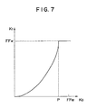
- a gamma correction amount A4 of the black image signal is increased, the gradation of the black components in the high-density portion is undesirably lost, as shown in Fig. 7.
- Gamma-converted minimum values K1 are plotted along the ordinate in Fig. 7, while the minimum values K0 before gamma conversion are plotted along the abscissa.
- Gamma conversion is performed using an 8-bit signal.
- the second embodiment provides an improvement in view of this drawback.
- UCR and inking amounts are represented by cubic functions.
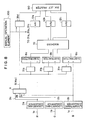
- FIG. 8 A circuit arrangement of the second embodiment is shown in Fig. 8.
- the same reference numerals as in Fig. 1 denote the same parts in Fig. 8.
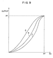
- Condition (1) is required to prevent saturation of the black components in a high-density portion.
- Condition (2) is required to prevent a decrease in saturation level in a low-density portion and generation of a pseudo edge.
- the cubic function generators 31a to 31d in Fig. 8 are replaced with a function generator for generating an arbitrary function g(K0).
- the function g(K0) must satisfy a condition that a dg(K0)/dK0 value linearly increases in the range of 0 ⁇ g ⁇ Q (0 ⁇ Q ⁇ FF).
- the quadratic functions of the first embodiment and the cubic functions of the second embodiment satisfy the above condition. If any function can satisfy this condition, it need not be expressed by a mathematical relation. Examples are given by a function in Fig. 10A or 10B.
- the UCR and black signals pass point (0,0). However, these signals may be shifted to pass point (T,0) in Fig. 11.
- black extraction and UCR are performed prior to masking after logarithmic conversion is completed.
- the present invention is not limited to this sequence. UCR may be performed after masking.
- both black extraction and UCR may be performed after masking.
- the modes of operations of the gamma correction circuits 12a, 12b, and 12c or the cubic function generators 31a, 31b, 31c, and 31d may be changed to reduce a total ink amount.
- a serial scan printer using a multinozzle head shown in Fig. 5 is used.
- the present invention is not limited to this printer.
- a serial scan printer having a single nozzle, a printer having a full multihead, or a printer utilizing electrostatic process may be used. With such a printer, an amount of toner applied to a recording medium can be reduced, and offset (undesirable toner transfer) of the convey roller can be prevented, thereby performing beautiful full-color image recording. Stripes formed between scanning cycles can be prevented in a serial scan printer according to the present invention, and therefore an effect of the present invention can be maximized.
- Figs. 12A and 12B are views for explaining formation of stripes. More specifically, Figs. 12A and 12B show recording patterns on a recording medium which are recorded by a serial scan ink-jet printer for performing image recording by repeating recording every width d in an order of (1), (2), and (3).
- Fig. 12A shows a case wherein printing is performed with one color and an amount of ink used is small.
- the ink can be sufficiently absorbed by the recording material, and the width of a printed image is almost equal to that of the recording width d . For this reason, when the recording head is scanned in the A direction after the recording head is scanned by d in the B direction, the stripes are not formed between the adjacent scanning cycles.
- a total amount of ink injected to the recording medium can be reduced, and therefore formation of stripes between adjacent scanning cycles can be prevented.
- the three color signals input to the image processor of the present invention may be supplied from an external device such as a memory or may be read by a reader having a CCD sensor or the like.
- the recording medium according to the present invention is not limited to a two-layered structure (Fig. 2) consisting of a transparent substrate and an ink absorbing layer.
- the recording medium may comprise a three-layered structure including an ink absorbing layer 102 which consists of an ink transporting layer 103 and an ink retaining layer 104.
- the injected ink can be strongly retained by the ink retaining layer, and an amount of ink left in the ink transporting layer is small. Therefore, an amount of ink in the inner surface of the transparent layer can be increased, thereby obtaining an image having a higher density.
- the effect of the present invention can be maximized in the back-print film since an amount of ink retained by its ink retaining layer is relatively small.
- subtractive primary (Y, M, and C) signals are obtained as the primary color signals.
- a minimum value is directly derived from the Y, M, and C signals as a value corresponding to the minimum value of the primary color signals.
- a maximum value of R, G, and B signals may be obtained as a value corresponding to the minimum value of the primary color signals. It is essential to obtain any value corresponding to the minimum value of the Y, M, and C signals.
- a value transformed by a continuous function having a minimum peak in accordance with a value corresponding to the minimum value of the primary color signals is given as a color reproduction signal. Therefore, a decrease in saturation level in a low-density portion and generation of a pseudo edge can be prevented. Therefore, a good color image can be reproduced.
Landscapes
- Engineering & Computer Science (AREA)
- Multimedia (AREA)
- Signal Processing (AREA)
- Color, Gradation (AREA)
- Color Image Communication Systems (AREA)
- Facsimile Image Signal Circuits (AREA)
- Ink Jet (AREA)
- Dot-Matrix Printers And Others (AREA)
Applications Claiming Priority (2)
| Application Number | Priority Date | Filing Date | Title |
|---|---|---|---|
| JP334791/87 | 1987-12-29 | ||
| JP62334791A JP2713935B2 (ja) | 1987-12-29 | 1987-12-29 | 画像処理方法 |
Publications (3)
| Publication Number | Publication Date |
|---|---|
| EP0323265A2 true EP0323265A2 (de) | 1989-07-05 |
| EP0323265A3 EP0323265A3 (en) | 1990-09-19 |
| EP0323265B1 EP0323265B1 (de) | 1995-08-30 |
Family
ID=18281273
Family Applications (1)
| Application Number | Title | Priority Date | Filing Date |
|---|---|---|---|
| EP19880312421 Expired - Lifetime EP0323265B1 (de) | 1987-12-29 | 1988-12-29 | Verfahren zur Farbbildverarbeitung und Gerät dafür |
Country Status (3)
| Country | Link |
|---|---|
| EP (1) | EP0323265B1 (de) |
| JP (1) | JP2713935B2 (de) |
| DE (1) | DE3854385T2 (de) |
Cited By (5)
| Publication number | Priority date | Publication date | Assignee | Title |
|---|---|---|---|---|
| EP0446019A3 (en) * | 1990-03-06 | 1992-08-26 | Canon Kabushiki Kaisha | Image processing apparatus and method |
| EP0540173A3 (en) * | 1991-10-29 | 1993-06-30 | Hewlett-Packard Company | Color separation in ink jet color graphics printing |
| EP0590852A3 (en) * | 1992-09-30 | 1994-05-18 | Hewlett Packard Co | Color separation in color graphics printing with limited memory |
| WO1996008913A1 (en) * | 1994-09-16 | 1996-03-21 | Linotype-Hell Ag | Black recalculation for arbitrary hsl corrections in cmy color space |
| WO1996008933A1 (en) * | 1994-09-12 | 1996-03-21 | Seiko Communications Systems, Inc. | Acknowledge back pager using secondary transmission source |
Families Citing this family (1)
| Publication number | Priority date | Publication date | Assignee | Title |
|---|---|---|---|---|
| JP5293530B2 (ja) | 2009-09-17 | 2013-09-18 | ブラザー工業株式会社 | 印刷制御装置および印刷制御プログラム |
Family Cites Families (4)
| Publication number | Priority date | Publication date | Assignee | Title |
|---|---|---|---|---|
| DE3313392A1 (de) * | 1982-04-14 | 1983-10-20 | Fuji Photo Film Co., Ltd., Minami Ashigara, Kanagawa | Verfahren und vorrichtung zur digitalen farbkorrektur |
| EP0266186B1 (de) * | 1986-10-29 | 1993-09-29 | Canon Kabushiki Kaisha | Farbbildlesegerät oder Farbbilderzeugungsgerät |
| JPH0738685B2 (ja) * | 1986-11-10 | 1995-04-26 | キヤノン株式会社 | カラ−画像記録装置 |
| GB2202708B (en) * | 1987-03-16 | 1991-05-29 | Mitsubishi Electric Corp | Color converting device |
-
1987
- 1987-12-29 JP JP62334791A patent/JP2713935B2/ja not_active Expired - Fee Related
-
1988
- 1988-12-29 EP EP19880312421 patent/EP0323265B1/de not_active Expired - Lifetime
- 1988-12-29 DE DE19883854385 patent/DE3854385T2/de not_active Expired - Lifetime
Cited By (8)
| Publication number | Priority date | Publication date | Assignee | Title |
|---|---|---|---|---|
| EP0446019A3 (en) * | 1990-03-06 | 1992-08-26 | Canon Kabushiki Kaisha | Image processing apparatus and method |
| US5457549A (en) * | 1990-03-06 | 1995-10-10 | Canon Kabushiki Kaisha | Method and apparatus for enhancing the speed of color image processing |
| EP0720349A1 (de) * | 1990-03-06 | 1996-07-03 | Canon Kabushiki Kaisha | Bildverarbeitungsvorrichtung und Verfahren |
| EP0540173A3 (en) * | 1991-10-29 | 1993-06-30 | Hewlett-Packard Company | Color separation in ink jet color graphics printing |
| US5475800A (en) * | 1991-10-29 | 1995-12-12 | Hewlett-Packard Company | Color separation in color graphics printing with limited memory |
| EP0590852A3 (en) * | 1992-09-30 | 1994-05-18 | Hewlett Packard Co | Color separation in color graphics printing with limited memory |
| WO1996008933A1 (en) * | 1994-09-12 | 1996-03-21 | Seiko Communications Systems, Inc. | Acknowledge back pager using secondary transmission source |
| WO1996008913A1 (en) * | 1994-09-16 | 1996-03-21 | Linotype-Hell Ag | Black recalculation for arbitrary hsl corrections in cmy color space |
Also Published As
| Publication number | Publication date |
|---|---|
| DE3854385T2 (de) | 1996-03-07 |
| JP2713935B2 (ja) | 1998-02-16 |
| DE3854385D1 (de) | 1995-10-05 |
| EP0323265A3 (en) | 1990-09-19 |
| JPH01174455A (ja) | 1989-07-11 |
| EP0323265B1 (de) | 1995-08-30 |
Similar Documents
| Publication | Publication Date | Title |
|---|---|---|
| US5172223A (en) | Method of processing a color image to obtain color and black reproduction signals | |
| EP0401023B1 (de) | Bildaufzeichnungssystem und Gerät dafür | |
| US4682216A (en) | Color image picture forming process and apparatus which improves the quality of the black portions of the picture | |
| US5825377A (en) | Method and apparatus for ink-jet recording with inks having different densities | |
| US5463471A (en) | Method and system of color halftone reproduction | |
| US5425134A (en) | Print color material amount determining method | |
| EP0369778B1 (de) | Bildaufzeichnungsgerät | |
| EP0720351A2 (de) | Verfahren und Gerät zur Erzeugung von Farbprobeabzügen | |
| GB2139450A (en) | Colour Picture Forming Apparatus | |
| US5745145A (en) | Ink jet recording apparatus and method | |
| US20030179410A1 (en) | Multilevel colour error-diffusion providing reduced sensitivity to printing process variability errors | |
| JPH07333822A (ja) | 印刷版画像の作成方法および装置 | |
| EP0449328B1 (de) | Bildverarbeitungsverfahren und -gerät | |
| US5596355A (en) | Color ink jet recording apparatus capable of high-quality printing of black portions | |
| US20070070464A1 (en) | Table creation method, table creation appartus, storage medium, and program | |
| EP0917352B1 (de) | Bildverarbeitungsvorrichtung und -verfahren | |
| US5091734A (en) | Color image recording utilizing color correction in accordance with a predetermined order of recording of multiple color agents | |
| EP0323265B1 (de) | Verfahren zur Farbbildverarbeitung und Gerät dafür | |
| US7443536B2 (en) | Method of generating color separation data and image processing apparatus | |
| JPH0983819A (ja) | 画像処理装置及び方法 | |
| US8098403B2 (en) | Color error diffusion with error signal offset | |
| CA2351238A1 (en) | A colorimetric method of manipulating inking in digital images | |
| US5875036A (en) | Image processing apparatus which separates an image signal according to density level | |
| US6249354B1 (en) | Image processing apparatus and method | |
| JP2556475B2 (ja) | カラ−画像処理装置 |
Legal Events
| Date | Code | Title | Description |
|---|---|---|---|
| PUAI | Public reference made under article 153(3) epc to a published international application that has entered the european phase |
Free format text: ORIGINAL CODE: 0009012 |
|
| AK | Designated contracting states |
Kind code of ref document: A2 Designated state(s): DE FR GB IT NL |
|
| PUAL | Search report despatched |
Free format text: ORIGINAL CODE: 0009013 |
|
| AK | Designated contracting states |
Kind code of ref document: A3 Designated state(s): DE FR GB IT NL |
|
| 17P | Request for examination filed |
Effective date: 19901231 |
|
| 17Q | First examination report despatched |
Effective date: 19930712 |
|
| GRAA | (expected) grant |
Free format text: ORIGINAL CODE: 0009210 |
|
| AK | Designated contracting states |
Kind code of ref document: B1 Designated state(s): DE FR GB IT NL |
|
| REF | Corresponds to: |
Ref document number: 3854385 Country of ref document: DE Date of ref document: 19951005 |
|
| ET | Fr: translation filed | ||
| ITF | It: translation for a ep patent filed | ||
| PLBE | No opposition filed within time limit |
Free format text: ORIGINAL CODE: 0009261 |
|
| STAA | Information on the status of an ep patent application or granted ep patent |
Free format text: STATUS: NO OPPOSITION FILED WITHIN TIME LIMIT |
|
| 26N | No opposition filed | ||
| REG | Reference to a national code |
Ref country code: GB Ref legal event code: IF02 |
|
| PGFP | Annual fee paid to national office [announced via postgrant information from national office to epo] |
Ref country code: NL Payment date: 20071219 Year of fee payment: 20 |
|
| PGFP | Annual fee paid to national office [announced via postgrant information from national office to epo] |
Ref country code: IT Payment date: 20071218 Year of fee payment: 20 |
|
| PGFP | Annual fee paid to national office [announced via postgrant information from national office to epo] |
Ref country code: GB Payment date: 20071228 Year of fee payment: 20 |
|
| PGFP | Annual fee paid to national office [announced via postgrant information from national office to epo] |
Ref country code: DE Payment date: 20071231 Year of fee payment: 20 |
|
| PGFP | Annual fee paid to national office [announced via postgrant information from national office to epo] |
Ref country code: FR Payment date: 20071220 Year of fee payment: 20 |
|
| REG | Reference to a national code |
Ref country code: GB Ref legal event code: PE20 Expiry date: 20081228 |
|
| PG25 | Lapsed in a contracting state [announced via postgrant information from national office to epo] |
Ref country code: NL Free format text: LAPSE BECAUSE OF EXPIRATION OF PROTECTION Effective date: 20081229 |
|
| NLV7 | Nl: ceased due to reaching the maximum lifetime of a patent |
Effective date: 20081229 |
|
| PG25 | Lapsed in a contracting state [announced via postgrant information from national office to epo] |
Ref country code: GB Free format text: LAPSE BECAUSE OF EXPIRATION OF PROTECTION Effective date: 20081228 |