EP0323301A1 - Steuerungsvorrichtung für volumetrische Motoren und Kompressoren - Google Patents
Steuerungsvorrichtung für volumetrische Motoren und Kompressoren Download PDFInfo
- Publication number
- EP0323301A1 EP0323301A1 EP88403173A EP88403173A EP0323301A1 EP 0323301 A1 EP0323301 A1 EP 0323301A1 EP 88403173 A EP88403173 A EP 88403173A EP 88403173 A EP88403173 A EP 88403173A EP 0323301 A1 EP0323301 A1 EP 0323301A1
- Authority
- EP
- European Patent Office
- Prior art keywords
- dead center
- top dead
- piston
- opening
- valve
- Prior art date
- Legal status (The legal status is an assumption and is not a legal conclusion. Google has not performed a legal analysis and makes no representation as to the accuracy of the status listed.)
- Ceased
Links
- 238000007789 sealing Methods 0.000 claims abstract description 44
- 238000009826 distribution Methods 0.000 claims abstract description 27
- 230000006835 compression Effects 0.000 claims abstract description 18
- 238000007906 compression Methods 0.000 claims abstract description 18
- 238000000034 method Methods 0.000 claims abstract description 16
- 239000012530 fluid Substances 0.000 claims abstract description 15
- 239000000919 ceramic Substances 0.000 claims description 14
- 239000000835 fiber Substances 0.000 claims description 12
- MCMNRKCIXSYSNV-UHFFFAOYSA-N Zirconium dioxide Chemical compound O=[Zr]=O MCMNRKCIXSYSNV-UHFFFAOYSA-N 0.000 claims description 8
- 235000001674 Agaricus brunnescens Nutrition 0.000 claims description 7
- 239000000203 mixture Substances 0.000 claims description 7
- HBMJWWWQQXIZIP-UHFFFAOYSA-N silicon carbide Chemical compound [Si+]#[C-] HBMJWWWQQXIZIP-UHFFFAOYSA-N 0.000 claims description 7
- 229910010271 silicon carbide Inorganic materials 0.000 claims description 7
- OKTJSMMVPCPJKN-UHFFFAOYSA-N Carbon Chemical compound [C] OKTJSMMVPCPJKN-UHFFFAOYSA-N 0.000 claims description 6
- 239000002131 composite material Substances 0.000 claims description 6
- 239000011159 matrix material Substances 0.000 claims description 5
- VYPSYNLAJGMNEJ-UHFFFAOYSA-N Silicium dioxide Chemical compound O=[Si]=O VYPSYNLAJGMNEJ-UHFFFAOYSA-N 0.000 claims description 4
- PNEYBMLMFCGWSK-UHFFFAOYSA-N aluminium oxide Inorganic materials [O-2].[O-2].[O-2].[Al+3].[Al+3] PNEYBMLMFCGWSK-UHFFFAOYSA-N 0.000 claims description 4
- 229910052799 carbon Inorganic materials 0.000 claims description 4
- XUIMIQQOPSSXEZ-UHFFFAOYSA-N Silicon Chemical compound [Si] XUIMIQQOPSSXEZ-UHFFFAOYSA-N 0.000 claims description 3
- TWNQGVIAIRXVLR-UHFFFAOYSA-N oxo(oxoalumanyloxy)alumane Chemical compound O=[Al]O[Al]=O TWNQGVIAIRXVLR-UHFFFAOYSA-N 0.000 claims description 3
- 229910052710 silicon Inorganic materials 0.000 claims description 3
- 239000010703 silicon Substances 0.000 claims description 3
- ZOXJGFHDIHLPTG-UHFFFAOYSA-N Boron Chemical compound [B] ZOXJGFHDIHLPTG-UHFFFAOYSA-N 0.000 claims description 2
- RTAQQCXQSZGOHL-UHFFFAOYSA-N Titanium Chemical compound [Ti] RTAQQCXQSZGOHL-UHFFFAOYSA-N 0.000 claims description 2
- 229910052782 aluminium Inorganic materials 0.000 claims description 2
- XAGFODPZIPBFFR-UHFFFAOYSA-N aluminium Chemical compound [Al] XAGFODPZIPBFFR-UHFFFAOYSA-N 0.000 claims description 2
- 229910052796 boron Inorganic materials 0.000 claims description 2
- 229910002804 graphite Inorganic materials 0.000 claims description 2
- 239000010439 graphite Substances 0.000 claims description 2
- 229910052814 silicon oxide Inorganic materials 0.000 claims description 2
- 229910052719 titanium Inorganic materials 0.000 claims description 2
- 239000010936 titanium Substances 0.000 claims description 2
- 238000006073 displacement reaction Methods 0.000 abstract description 4
- 238000002485 combustion reaction Methods 0.000 description 12
- 239000007789 gas Substances 0.000 description 9
- 238000004880 explosion Methods 0.000 description 6
- 230000035939 shock Effects 0.000 description 5
- 238000004891 communication Methods 0.000 description 3
- RVTZCBVAJQQJTK-UHFFFAOYSA-N oxygen(2-);zirconium(4+) Chemical compound [O-2].[O-2].[Zr+4] RVTZCBVAJQQJTK-UHFFFAOYSA-N 0.000 description 3
- 229910001928 zirconium oxide Inorganic materials 0.000 description 3
- 244000027321 Lychnis chalcedonica Species 0.000 description 2
- 229910010293 ceramic material Inorganic materials 0.000 description 2
- 238000003780 insertion Methods 0.000 description 2
- 230000037431 insertion Effects 0.000 description 2
- 238000005461 lubrication Methods 0.000 description 2
- 244000251953 Agaricus brunnescens Species 0.000 description 1
- UGFAIRIUMAVXCW-UHFFFAOYSA-N Carbon monoxide Chemical compound [O+]#[C-] UGFAIRIUMAVXCW-UHFFFAOYSA-N 0.000 description 1
- 240000008042 Zea mays Species 0.000 description 1
- 239000000956 alloy Substances 0.000 description 1
- 229910045601 alloy Inorganic materials 0.000 description 1
- 229910002091 carbon monoxide Inorganic materials 0.000 description 1
- 229910052681 coesite Inorganic materials 0.000 description 1
- 239000002826 coolant Substances 0.000 description 1
- 229910052906 cristobalite Inorganic materials 0.000 description 1
- 230000000593 degrading effect Effects 0.000 description 1
- 230000006866 deterioration Effects 0.000 description 1
- 230000000694 effects Effects 0.000 description 1
- 239000000446 fuel Substances 0.000 description 1
- 239000000314 lubricant Substances 0.000 description 1
- 238000003754 machining Methods 0.000 description 1
- 239000007769 metal material Substances 0.000 description 1
- 229910044991 metal oxide Inorganic materials 0.000 description 1
- 150000004706 metal oxides Chemical class 0.000 description 1
- 230000007935 neutral effect Effects 0.000 description 1
- 239000000377 silicon dioxide Substances 0.000 description 1
- 235000012239 silicon dioxide Nutrition 0.000 description 1
- 235000014347 soups Nutrition 0.000 description 1
- 229910052682 stishovite Inorganic materials 0.000 description 1
- 229910052905 tridymite Inorganic materials 0.000 description 1
Images

Classifications
-
- F—MECHANICAL ENGINEERING; LIGHTING; HEATING; WEAPONS; BLASTING
- F01—MACHINES OR ENGINES IN GENERAL; ENGINE PLANTS IN GENERAL; STEAM ENGINES
- F01L—CYCLICALLY OPERATING VALVES FOR MACHINES OR ENGINES
- F01L7/00—Rotary or oscillatory slide valve-gear or valve arrangements
- F01L7/16—Sealing or packing arrangements specially therefor
-
- F—MECHANICAL ENGINEERING; LIGHTING; HEATING; WEAPONS; BLASTING
- F01—MACHINES OR ENGINES IN GENERAL; ENGINE PLANTS IN GENERAL; STEAM ENGINES
- F01L—CYCLICALLY OPERATING VALVES FOR MACHINES OR ENGINES
- F01L11/00—Valve arrangements in working piston or piston-rod
- F01L11/02—Valve arrangements in working piston or piston-rod in piston
-
- F—MECHANICAL ENGINEERING; LIGHTING; HEATING; WEAPONS; BLASTING
- F02—COMBUSTION ENGINES; HOT-GAS OR COMBUSTION-PRODUCT ENGINE PLANTS
- F02B—INTERNAL-COMBUSTION PISTON ENGINES; COMBUSTION ENGINES IN GENERAL
- F02B75/00—Other engines
- F02B75/02—Engines characterised by their cycles, e.g. six-stroke
- F02B2075/022—Engines characterised by their cycles, e.g. six-stroke having less than six strokes per cycle
- F02B2075/027—Engines characterised by their cycles, e.g. six-stroke having less than six strokes per cycle four
-
- F—MECHANICAL ENGINEERING; LIGHTING; HEATING; WEAPONS; BLASTING
- F02—COMBUSTION ENGINES; HOT-GAS OR COMBUSTION-PRODUCT ENGINE PLANTS
- F02B—INTERNAL-COMBUSTION PISTON ENGINES; COMBUSTION ENGINES IN GENERAL
- F02B3/00—Engines characterised by air compression and subsequent fuel addition
- F02B3/06—Engines characterised by air compression and subsequent fuel addition with compression ignition
Definitions
- the invention relates to a method and a device for a positive displacement motor and compressor.
- the invention essentially relates to a method and a device for forced distribution of a fluid by means of a piston treatment chamber, comprising sealing means ensuring a substantially perfect seal at top dead center, a motor, a compressor and a device operating by pulses comprising application thereof, and sealing means, in particular a soup per se.
- Document FR-A-1 474 890 discloses a device for forced distribution of a fluid from a so-called intake pipe to a so-called exhaust pipe by means of a treatment chamber which may include compression, for example by the presence of a piston 4, comprising a distributor element 8 rotatably mounted in a cylinder head element A which has at least three non-aligned openings communicating with each other, including an intake opening 6 communicating freely with the pipe of intake, an intermediate opening 5 communicating freely with the treatment chamber and an exhaust opening 7 communicating freely with the exhaust pipe.
- the distributor element 8 comprises a lumen 9 giving access to the treatment chamber, during its rotation, to only one pipe at a time (see FIGS. 1 to 5).
- the distributor element 8 is rotated continuously in all circumstances and is placed in the cylinder head so as to ensure by friction the perfect seal between the treatment chamber and the intake and exhaust pipes (page 1, lines 17 to 25).
- the seal can be reinforced by adapting segments 10.
- This device is used in this document for the admission and evacuation of gases from explosion engines, the treatment then constituting an explosion chamber in which is disposed a conventional piston 4 of the internal combustion engines.
- An opening is also provided in the cylinder head for the insertion of an ignition element 11. It is indicated that the device adapts perfectly to the internal combustion, two-stroke, diesel engine, and to any type of fuel ( page 2, lines 7-9).
- Document FR-A-2 090 414 describes a similar distribution device, the cylinder head (7) of which consists of two parts allowing the machining of the whole assembly, plus independent tightening, the cylinder head being made of special aluminum, while that the shaft (1) and the rings (2 and 8) are in a special shape in order to reduce the coefficient of friction to a minimum and to solve the problems of expansion.
- Document FR-A-2 184 209 also relates to a similar distribution device used interchangeably for internal combustion (internal explosion) engines as well as compressors or pumps. It is emphasized that in the device ensuring the same functions, the systems employed (valve or valve controlled by a camshaft, often with several intermediaries) brake the fluids by imposing an obstacle on their path towards the cylinder head chamber, open to outside. In addition, the reciprocating movement of these systems represents significant inertia degrading the performance of the assembly and limiting the operating regime, while repeated shocks offer a risk of deterioration of these elements (page 1, lines 4 to 12).
- Document FR-A-2 417 636 also describes a rotary distribution device used in four-stroke engines quite similar with a distributor element animated by a continuous rotary movement around a horizontal axis perpendicular to that of the engine cylinder.
- Document FR-A-1 573 321 describes an internal combustion engine, a distributor device with discontinuous rotation by the use of a drive system with discontinuous rotation with a Maltese cross. Such a device has not found practical application due to the impossibility of obtaining the necessary seal and a sufficient speed of rotation with the metallic materials or alloys used to make such motors.
- FR-86 13 525, FR-86 17 438, FR-86 17 439 and FR-86 17 440 relate to a rotary distributor device with sealing segments.
- a particularly advantageous application relates to motors, these motors being made of specific ceramic having high characteristics of resistance to high rotational speeds as well as resistance to thermal shock, having a particularly increased service life compared to previous ceramics.
- the major drawback of the prior distribution systems and particularly of the rotary distribution systems lies in a lack of tightness when the piston is in top dead center or in the vicinity of top dead center and in particular at the end of the compression cycle or especially at the time of triggering on ignition at the precise point where a shock wave gives a pressure which can, in certain cases, reach from 100 to 150 times the compression rate, level reached by diesel engines.
- the present invention therefore aims to solve the new technical problem consisting in the supply of a solution which makes it possible to achieve a substantially perfect seal in all types of distribution comprising a treatment chamber which may comprise a compression in which an alternately moves a psiton, when the piston is at or near this top dead center.
- the present invention also aims to solve the new technical problem consisting in providing a solution which makes it possible to provide a substantially perfect seal at the top dead center or in the vicinity of the top dead center of the piston of internal combustion engines, or of the reciprocating compressors, or pulse-operated devices, including pulley-reactors.
- the present invention also aims to solve the new technical problem consisting in providing a solution which makes it possible to ensure a substantially perfect seal at the top dead center or in the vicinity of this top dead center, the piston moving alternately in a treatment chamber, which can be used equally for conventional two- or four-stroke engines, as well as for diesel engines, and which prevents any mixture of fresh gas admitted and exhausted burnt gas, as well as any discharge of exhaust gases into the intake circuit.
- Another object of the present invention is to solve the new technical problem consisting in providing a solution which makes it possible to achieve a substantially perfect seal. at top dead center, at the end of exhaust and before the admission of internal combustion engines which do not require any lubrication or any adjustment and which contain no possibility of time shift, which are therefore foolproof whatever the speeds of rotation and compression ratios and which are also very simple.
- the present invention provides a method of forced distribution of a fluid from at least one so-called intake pipe to at least one so-called exhaust pipe via a treatment chamber which may comprise compression, said treatment chamber comprising at least one opening for selective communication between said chamber with said intake pipe and / or said exhaust pipe; as well as a piston moving alternately in said chamber between a position furthest from said opening commonly called bottom dead center and a position closest to said opening commonly called top dead center, characterized in that means are provided for 'sealing capable of ensuring a substantially perfect seal at the top dead center of said piston or in the vicinity of said top dead center, between said treatment chamber and said opening; these sealing means are activated at an appropriate time to ensure sealing at the top dead center or in the vicinity of said top dead center and these sealing means are deactivated outside the top dead center or in the vicinity of the top dead center, to allow the passage of said fluid in said opening.
- the aforementioned sealing means are activated just before the top dead center and deactivated just after the top dead center.
- the aforementioned sealing means are integral with the piston and are advantageously directed towards said opening.
- a preferred embodiment of the sealing means consists of a valve, preferably a mushroom.
- valve comprises a stem which is mounted in translation in a cavity of the piston head, preferably in translation coaxial with the axis of the piston.
- the present invention also provides a device for forced distribution of a fluid from at least one so-called intake pipe to at least one so-called exhaust pipe via a treatment chamber which may include a compression, said chamber comprising at least one opening selectively communicating with said intake pipe and / or said exhaust pipe; and a piston alternately moving in said chamber between a position furthest from said opening commonly called bottom dead center and a position closest to said opening commonly called top dead center, characterized in that it comprises sealing means selectively activated to ensure a substantially perfect seal at the top dead center of the piston or in the vicinity of said top dead center, or deactivated to allow free passage of said fluid in said opening for entering or leaving said chamber outside top dead center or the near top dead center.
- the sealing means are integral with the piston.
- these sealing means comprise a valve, preferably a mushroom valve.
- this valve comprises a stem which is mounted in translation in a cavity of the head of the piston, preferably in translation coaxial with the axis of the piston.
- Unidirectional pushing means are advantageously arranged in the cavity to permanently push the valve in the direction of said opening.
- the aforementioned valve is made of structural ceramic.
- An exemplary embodiment of this structural ceramic valve consists of a composite structural ceramic comprising a matrix reinforced with fibers which can be oriented two-dimensionally or three-dimensionally.
- this composite ceramic material can be prepared according to a process described in the prior application FR-84-14 800 which is incorporated here by reference.
- these fibers are advantageously chosen from the group consisting of silicon carbide, zirconia, alumina or mixtures of aluminum oxide and silicon oxide (Al2O3 SiO2).
- the matrix in which the fibers are immersed is advantageously chosen from the group consisting of zirconia (ZrO2), alumina (Al2O3) or alternatively mixtures of aluminum oxide and silicon (Al2O3-SiO2).
- the composite ceramic can be prepared according to the process described in prior French application FR-85-19 436.
- the fibers woven in three dimensions are advantageously chosen from silicon carbide, a mixture of carbide of silicon and titanium, boron, carbon, while the matrix can advantageously be made of silicon carbide, graphite or even carbon or even zirconium oxide (ZrO2).
- the piston head has a bulge protruding towards the inside of the piston to allow the housing of the valve stem.
- the aforementioned treatment chamber has an oval section, in which a piston with an oval section is arranged, the aforementioned opening also being of oval section and the aforementioned valves then also being of oval section.
- the present invention covers engines, in particular two- or four-stroke engines, petrol or diesel, and advantageously those with rotary distribution, as well as piston compressors, apparatuses operating with pulses, especially pulso-reactors, equipped with such a distribution device defined above.
- the present invention also relates to the sealing means, in particular a valve, as defined above.
- the invention makes it possible to bring a precise and total sealing moment to the top dead center of the piston, which is essential in particular in internal combustion engines at the maximum of compression and at the time of the birth of the ignition shock.
- valve head and valve stem (s) are never licked by hot and corrosive exhaust gases during the exhaust cycle, which ensures a perfect geometric shape of the valve head throughout the duration of engine life.
- the invention can be used in engines already comprising conventional valves where the valve according to the invention can thus provide additional support on the heads of exhaust valves.
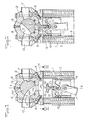
- FIGS. 1 to 5 With reference to FIGS. 1 to 5, and more particularly to FIGS. 1 and 2, one can see the conventional cylinder block of a engine reference 1, comprising an openwork part referenced 2 in which the coolant circulates.
- the inner liners are referenced 3 and define a treatment chamber 30 here constituting an explosion chamber.
- This engine block is capped by the cylinder head advantageously made of ceramic formed by two half-cylinder heads respectively lower 4 and upper 8.
- the spark plugs 5 and 6 are arranged in the lower half-cylinder head 4 in the lower half-cylinder head 4 and an opening 7 for communication with the treatment 30 and with either the intake channel 10 or the exhaust channel 11.
- the upper half-cylinder head 8 defines with the lower half-cylinder head 4 passageways with the conduits d intake 10 and exhaust 11, as well as a circular central cylindrical circular opening 12 in the axis and contained in the plane of symmetry of the treatment chamber 30.
- a distributor element 13 which is advantageously that described in the applicant's prior documents FR-86-13 525 and FR-86-13 438, which are incorporated here by reference.
- This dispensing element 13 thus comprises an opening 32 being selectively in communication with the treatment chamber 30 with the intake pipe 10 as shown in FIG. 1 and with the exhaust pipe 11, an intermediate position being shown in FIG. 2.
- sealing centering segments marked 14A, 14B are advantageously placed. , 14C.
- the distributor element 13 and the cylinder head formed by the two half-cylinder heads 4, 8 are advantageously made of suitable ceramic of the technical structural ceramic type based on metal oxide and reinforced with fibers giving composite ceramics or ceramic-ceramics, such as described in the applicant's prior documents set out above.
- This piston 15 is integral with the connecting rods 17 and is shown at half travel in FIG. 1 and at top dead center in Figure 2, which is the position closest to the opening 7, while the position farthest from the opening 7 is commonly called bottom dead center.
- the distribution device thus defined applied to an internal combustion engine, according to an advantageous embodiment, is characterized in that it comprises sealing means 18 selectively activated to ensure a substantially sealing perfect at the top dead center of the piston 15 or in the vicinity of said top dead center, as shown in FIG. 2, or deactivated to allow free passage of said fluid through said opening 7 to enter or exit said chamber 30 outside of neutral top, as shown in Figure 1.
- these sealing means 18 are integral with the piston 15, as shown.
- these sealing means 18 comprise at least one valve 20 which is shown separately in perspective in FIG. 5.
- This valve 20 comprises at least one shank, here three shanks 22.
- This valve 20 and advantageously mounted in translation in a cavity 24 formed in the head of the piston 15, by being mounted there preferably in translation or axial to the axis XX of the piston 15 and therefore of the treatment chamber 30.
- Unidirectional pushing means 26 are advantageously arranged in the cavity 24 so as to permanently push the valve 20 in the direction of the opening 7.
- the dimension of the opening 7 is shown in dotted lines in FIG. 3, as well as the range of the active surface 21 of the valve 20. It can be seen that, naturally, the range of the active surface 21 occupies an area greater than the surface of the opening 7 so as to be able to ensure a perfect seal when applying the valve 20 against the edges of the opening 7.
- this valve 20 is preferably in the form of a mushroom, as clearly visible in particular in FIG. 4.
- the active surface 21 of the valve 20 is convex.
- This active surface 21 advantageously cooperates with a flat 28 of annular section S formed in the lower part of the cylinder head 4 near the opening 7 so as to ensure a perfect seal between the valve 20 and the edge of the opening 7 preventing any passage of the fluid between the treatment chamber 30 and the opening 7.
- each stem 22 of the valve 20 is provided with an annular groove 36 for housing a conventional segment 38, which is tightened to allow the insertion of the valve 20 into the cavity 24.
- the segment 38 takes its final extension and locks the tail 22 in the cavity 24, this segment 38 being usually pushed permanently by the unidirectional pushing means 26 disposed under the tail 22, against the shoulder stop 34, as shown in FIG. 4. In this position, the valve 20 is capable of carrying out an axial displacement or axial stroke of a distance h in the direction opposite to the opening 7.
- the length of the shank (s) 22 is provided such that the valve 20 is applied against the flat 28 of the lower cylinder head 4 before the piston 15 reaches the top dead center, advantageously, like this is clearly understandable, when the piston 15 is at distance h from the top dead center.
- FIG. 1 where it can be seen that during the intake cycle the piston head 15 is going down and the valve 20 is located in the part furthest from the piston head 15 since '' It is pushed back by the unidirectional pushing means 26, while Figure 2 showing the compression cycle, we see that the piston is in top dead center and that the valve 20 has completely closed the orifice 7 while compressing the unidirectional pushing means 26, the distance from the valve head 20 to the piston head 15 between the top dead centers and the rest of the stroke of the piston 15 is constituted by the height h shown in FIG. 4.
- such a distribution device equipped with the sealing means previously mentioned referenced 18 makes it possible to implement the distribution method previously stated and that it finds a particularly advantageous application in the internal combustion engines that they either two or four stroke, or petrol or diesel, in particular in engines with rotary distribution and whose treatment chamber is of oval section, as well as the piston.
- An advantageous application also relates to piston compressors as well as devices operating by pulses, in particular pulso-reactors.
- the invention also covers the sealing means 18, in particular the valve 20 as a new industrial product as well as the pistons 15 fitted with such sealing means.
Landscapes
- Engineering & Computer Science (AREA)
- Mechanical Engineering (AREA)
- General Engineering & Computer Science (AREA)
- Cylinder Crankcases Of Internal Combustion Engines (AREA)
- Compressor (AREA)
- Control Of Positive-Displacement Pumps (AREA)
Applications Claiming Priority (2)
| Application Number | Priority Date | Filing Date | Title |
|---|---|---|---|
| FR8717594 | 1987-12-16 | ||
| FR8717594A FR2624910A1 (fr) | 1987-12-16 | 1987-12-16 | Procede et dispositif de distribution pour moteur et compresseur volumetriques |
Publications (1)
| Publication Number | Publication Date |
|---|---|
| EP0323301A1 true EP0323301A1 (de) | 1989-07-05 |
Family
ID=9357946
Family Applications (1)
| Application Number | Title | Priority Date | Filing Date |
|---|---|---|---|
| EP88403173A Ceased EP0323301A1 (de) | 1987-12-16 | 1988-12-14 | Steuerungsvorrichtung für volumetrische Motoren und Kompressoren |
Country Status (4)
| Country | Link |
|---|---|
| US (1) | US4889088A (de) |
| EP (1) | EP0323301A1 (de) |
| JP (1) | JPH025701A (de) |
| FR (1) | FR2624910A1 (de) |
Cited By (2)
| Publication number | Priority date | Publication date | Assignee | Title |
|---|---|---|---|---|
| WO1991000953A1 (en) * | 1989-07-06 | 1991-01-24 | Peter William Gabelish | A rotary valve |
| ES2049602A2 (es) * | 1991-10-07 | 1994-04-16 | Belda Mico | "nueva valvula para motores de explosion de cuatro tiempos". |
Families Citing this family (3)
| Publication number | Priority date | Publication date | Assignee | Title |
|---|---|---|---|---|
| DE69229007T2 (de) * | 1991-01-16 | 1999-10-21 | Sgl Carbon Composites, Inc. | Verbundwerkstoffe aus siliciumcarbidfaserarmiertem Kohlenstoff |
| DE10353088A1 (de) * | 2003-11-11 | 2005-06-16 | Schott Ag | Bauteil eines Ventiltriebes sowie Ventiltriebe, insbesondere für Verbrennungskraftmaschinen |
| US7089893B1 (en) | 2004-07-13 | 2006-08-15 | David Ostling | Combustion engine valve system |
Citations (8)
| Publication number | Priority date | Publication date | Assignee | Title |
|---|---|---|---|---|
| BE383712A (de) * | ||||
| FR396670A (fr) * | 1908-02-01 | 1909-04-17 | Societe A. Peugeot, Tony Huber Et Cie | Dispositif de cylindres et de pistons pour moteurs à deux temps |
| FR424669A (fr) * | 1911-01-07 | 1911-05-20 | Georges Cochot | Système de distribution pour moteurs à explosions |
| FR433338A (fr) * | 1911-04-19 | 1912-01-04 | Gustave Tzaut | Systèmes de distribution pour moteurs à explosion |
| FR2075721A5 (de) * | 1970-01-20 | 1971-10-08 | Owatonna Tool Co | |
| US4359022A (en) * | 1979-08-02 | 1982-11-16 | Tokyo Shibaura Denki Kabushiki Kaisha | Valve for an internal combustion engine |
| GB2170860A (en) * | 1985-01-29 | 1986-08-13 | Honda Motor Co Ltd | Oval cylinder i c engine and valve arrangement therefor |
| DE3637953A1 (de) * | 1986-11-07 | 1988-05-11 | Heinz Ussner | Arbeitsverfahren einer kolbenkraftmaschine, sowie nach diesem verfahren arbeitende kolbenkraftmaschine |
Family Cites Families (13)
| Publication number | Priority date | Publication date | Assignee | Title |
|---|---|---|---|---|
| FR1474890A (fr) * | 1966-02-08 | 1967-03-31 | Dispositif rotatif d'admission et d'évacuation des gaz de moteur à explosion | |
| CH487335A (fr) * | 1967-06-14 | 1970-03-15 | Henvaux Jean | Dispositif de distribution pour moteur à combustion interne |
| FR2184209A5 (de) * | 1972-05-12 | 1973-12-21 | Marguerite Georges | |
| US4098238A (en) * | 1976-01-28 | 1978-07-04 | Alto Automotive, Inc. | Rotary valve system for motors and the like having improved sealing means |
| FR2417636A1 (fr) * | 1978-02-15 | 1979-09-14 | Pradenc Jean | Dispositif de distribution rotative pour moteurs a 4 temps a combustion interne |
| US4218994A (en) * | 1978-12-14 | 1980-08-26 | Reed Ewell R | Fluid intake and exhaust assemblies for positive displacement apparatus |
| US4359027A (en) * | 1980-09-22 | 1982-11-16 | Outboard Marine Corporation | Two-cycle internal combustion engine having high swirl combustion chamber |
| JPS6017216A (ja) * | 1983-07-08 | 1985-01-29 | Hitachi Ltd | 内燃機関 |
| JPS60190650A (ja) * | 1984-03-13 | 1985-09-28 | Ngk Insulators Ltd | エンジン用ピストンおよびその製造法 |
| US4523557A (en) * | 1984-05-04 | 1985-06-18 | Duke Fox | Model airplane engine |
| DE3507108A1 (de) * | 1985-02-28 | 1986-08-28 | Ficht GmbH, 8011 Kirchseeon | Viertakt-brennkraftkolbenmaschine |
| FR2604477B1 (fr) * | 1986-09-29 | 1991-05-24 | Innolab | Procede d'amelioration du fonctionnement des dispositifs de distribution rotatifs a distribution rotative discontinue, dispositif de distribution et utilisation de ce dispositif dans des moteurs a combustion interne, des compresseurs a piston ou des appareils a fonctionnement par pulsion, notamment des pulso-reacteurs |
| FR2608210A2 (fr) * | 1986-09-29 | 1988-06-17 | Innolab | Dispositif de distribution rotatif a rotation discontinue par croix de malte comportant des moyens pour faire roter le doigt de la croix de malte |
-
1987
- 1987-12-16 FR FR8717594A patent/FR2624910A1/fr not_active Withdrawn
-
1988
- 1988-12-14 EP EP88403173A patent/EP0323301A1/de not_active Ceased
- 1988-12-15 US US07/284,655 patent/US4889088A/en not_active Expired - Fee Related
- 1988-12-15 JP JP63317547A patent/JPH025701A/ja active Pending
Patent Citations (8)
| Publication number | Priority date | Publication date | Assignee | Title |
|---|---|---|---|---|
| BE383712A (de) * | ||||
| FR396670A (fr) * | 1908-02-01 | 1909-04-17 | Societe A. Peugeot, Tony Huber Et Cie | Dispositif de cylindres et de pistons pour moteurs à deux temps |
| FR424669A (fr) * | 1911-01-07 | 1911-05-20 | Georges Cochot | Système de distribution pour moteurs à explosions |
| FR433338A (fr) * | 1911-04-19 | 1912-01-04 | Gustave Tzaut | Systèmes de distribution pour moteurs à explosion |
| FR2075721A5 (de) * | 1970-01-20 | 1971-10-08 | Owatonna Tool Co | |
| US4359022A (en) * | 1979-08-02 | 1982-11-16 | Tokyo Shibaura Denki Kabushiki Kaisha | Valve for an internal combustion engine |
| GB2170860A (en) * | 1985-01-29 | 1986-08-13 | Honda Motor Co Ltd | Oval cylinder i c engine and valve arrangement therefor |
| DE3637953A1 (de) * | 1986-11-07 | 1988-05-11 | Heinz Ussner | Arbeitsverfahren einer kolbenkraftmaschine, sowie nach diesem verfahren arbeitende kolbenkraftmaschine |
Cited By (2)
| Publication number | Priority date | Publication date | Assignee | Title |
|---|---|---|---|---|
| WO1991000953A1 (en) * | 1989-07-06 | 1991-01-24 | Peter William Gabelish | A rotary valve |
| ES2049602A2 (es) * | 1991-10-07 | 1994-04-16 | Belda Mico | "nueva valvula para motores de explosion de cuatro tiempos". |
Also Published As
| Publication number | Publication date |
|---|---|
| FR2624910A1 (fr) | 1989-06-23 |
| US4889088A (en) | 1989-12-26 |
| JPH025701A (ja) | 1990-01-10 |
Similar Documents
| Publication | Publication Date | Title |
|---|---|---|
| EP0100713B1 (de) | Dichtungselement für eine Gaszyklus-Regelvorrichtung einer Brennkammer | |
| EP0252935B1 (de) | Zweitaktbrennkraftmaschine | |
| EP2279332B1 (de) | Verbrennungsmotor | |
| FR2692624A1 (fr) | Piston pour moteurs à combustion interne. | |
| EP0258119B1 (de) | Kolben für eine hin- und hergehende, Fluidum verdichtende Maschine und Maschine, versehen mit solchen Kolben | |
| FR3086006A1 (fr) | Piston pour moteur a combustion interne | |
| FR2624910A1 (fr) | Procede et dispositif de distribution pour moteur et compresseur volumetriques | |
| WO1995026460A1 (fr) | Moteur a combustion interne, a obturateurs de distribution rotatifs | |
| EP0024994A1 (de) | Verfahren und Vorrichtung für die Verbesserung des Wirkungsgrades einer Brennkraftmaschine durch selektive Änderung des Kompressionsverhältnisses in Hinsicht auf Motorbelastung | |
| FR2842867A1 (fr) | Actionneur hydraulique de soupapes pour moteurs a pistons | |
| EP0250960B1 (de) | Brennkraftmaschine | |
| EP0144277A1 (de) | Verfahren zur besseren Funktion einer Brennkraftmaschine, Vorrichtung zur Anwendung dieses Verfahrens und eine Brennkraftmaschine ausgerüstet mit dieser Vorrichtung | |
| FR2671137A1 (fr) | Moteur a deux temps a balayage retarde du cylindre. | |
| FR2745328A1 (fr) | Perfectionnement aux moteurs a combustion interne a deux temps a balayage en boucle | |
| FR2743605A1 (fr) | Structure d'etancheite pour cylindre et culasse de moteur a combustion interne du type a pistons et procede pour la pose de celle-ci | |
| EP0069039B1 (de) | Aufgeladene Brennkraftmaschine | |
| CH642143A5 (en) | Intake/exhaust unit for a four-stroke internal combustion engine | |
| FR2566459A1 (fr) | Procede d'amelioration du fonctionnement d'un moteur a combustion interne et moteur a combustion interne a fonctionnement ameliore et structure simplifiee | |
| FR2604477A1 (fr) | Procede d'amelioration du fonctionnement des dispositifs de distribution rotatifs a distribution rotative discontinue, dispositif de distribution et utilisation de ce dispositif dans des moteurs a combustion interne, des compresseurs a piston ou des appareils a fonctionnement par pulsion, notamment des pulso-reacteurs | |
| BE371163A (de) | ||
| FR2531139A1 (fr) | Dispositif de controle d'un circuit de gaz d'une chambre de combustion | |
| CH542999A (fr) | Procédé et dispositif de suralimentation pour moteurs à combustion interne à quatre temps | |
| FR2898383A1 (fr) | Ensemble mecanique pour la realisation de machines telles que compresseurs, moteurs thermiques ou autres, dotees d'un cylindre et d'un piston | |
| FR3093345A1 (fr) | Ensemble tiroir | |
| FR2608209A1 (fr) | Dispositif de distribution rotatif a distribution rotative discontinue, pourvu de moyens de resonance |
Legal Events
| Date | Code | Title | Description |
|---|---|---|---|
| PUAI | Public reference made under article 153(3) epc to a published international application that has entered the european phase |
Free format text: ORIGINAL CODE: 0009012 |
|
| AK | Designated contracting states |
Kind code of ref document: A1 Designated state(s): AT BE CH DE ES GB GR IT LI LU NL SE |
|
| 17P | Request for examination filed |
Effective date: 19891228 |
|
| 17Q | First examination report despatched |
Effective date: 19910320 |
|
| STAA | Information on the status of an ep patent application or granted ep patent |
Free format text: STATUS: THE APPLICATION HAS BEEN REFUSED |
|
| 18R | Application refused |
Effective date: 19920306 |