EP0323340A2 - Connecteur à percement d'isolation - Google Patents
Connecteur à percement d'isolation Download PDFInfo
- Publication number
- EP0323340A2 EP0323340A2 EP88403320A EP88403320A EP0323340A2 EP 0323340 A2 EP0323340 A2 EP 0323340A2 EP 88403320 A EP88403320 A EP 88403320A EP 88403320 A EP88403320 A EP 88403320A EP 0323340 A2 EP0323340 A2 EP 0323340A2
- Authority
- EP
- European Patent Office
- Prior art keywords
- connector
- connector body
- cover
- piercing
- wires
- Prior art date
- Legal status (The legal status is an assumption and is not a legal conclusion. Google has not performed a legal analysis and makes no representation as to the accuracy of the status listed.)
- Granted
Links
Images





Classifications
-
- H—ELECTRICITY
- H01—ELECTRIC ELEMENTS
- H01R—ELECTRICALLY-CONDUCTIVE CONNECTIONS; STRUCTURAL ASSOCIATIONS OF A PLURALITY OF MUTUALLY-INSULATED ELECTRICAL CONNECTING ELEMENTS; COUPLING DEVICES; CURRENT COLLECTORS
- H01R12/00—Structural associations of a plurality of mutually-insulated electrical connecting elements, specially adapted for printed circuits, e.g. printed circuit boards [PCB], flat or ribbon cables, or like generally planar structures, e.g. terminal strips, terminal blocks; Coupling devices specially adapted for printed circuits, flat or ribbon cables, or like generally planar structures; Terminals specially adapted for contact with, or insertion into, printed circuits, flat or ribbon cables, or like generally planar structures
- H01R12/50—Fixed connections
- H01R12/59—Fixed connections for flexible printed circuits, flat or ribbon cables or like structures
- H01R12/65—Fixed connections for flexible printed circuits, flat or ribbon cables or like structures characterised by the terminal
- H01R12/67—Fixed connections for flexible printed circuits, flat or ribbon cables or like structures characterised by the terminal insulation penetrating terminals
- H01R12/675—Fixed connections for flexible printed circuits, flat or ribbon cables or like structures characterised by the terminal insulation penetrating terminals with contacts having at least a slotted plate for penetration of cable insulation, e.g. insulation displacement contacts for round conductor flat cables
-
- H—ELECTRICITY
- H01—ELECTRIC ELEMENTS
- H01R—ELECTRICALLY-CONDUCTIVE CONNECTIONS; STRUCTURAL ASSOCIATIONS OF A PLURALITY OF MUTUALLY-INSULATED ELECTRICAL CONNECTING ELEMENTS; COUPLING DEVICES; CURRENT COLLECTORS
- H01R4/00—Electrically-conductive connections between two or more conductive members in direct contact, i.e. touching one another; Means for effecting or maintaining such contact; Electrically-conductive connections having two or more spaced connecting locations for conductors and using contact members penetrating insulation
- H01R4/24—Connections using contact members penetrating or cutting insulation or cable strands
- H01R4/2416—Connections using contact members penetrating or cutting insulation or cable strands the contact members having insulation-cutting edges, e.g. of tuning fork type
- H01R4/242—Connections using contact members penetrating or cutting insulation or cable strands the contact members having insulation-cutting edges, e.g. of tuning fork type the contact members being plates having a single slot
- H01R4/2425—Flat plates, e.g. multi-layered flat plates
- H01R4/2429—Flat plates, e.g. multi-layered flat plates mounted in an insulating base
- H01R4/2433—Flat plates, e.g. multi-layered flat plates mounted in an insulating base one part of the base being movable to push the cable into the slot
Definitions
- This invention relates to an insulation-piercing connector capable of connecting wires in high density.
- a plurality of contacts each formed with a pressing slit 2a at a center of its tail 2, and oblique blades 2b on both sides thereof.
- connection wires 3 are pressed into the pressing slits 2a of the tails of contacts by a cover B, so that the blades 2b of each of the contacts 2b are caused to penetrate into a coating 3a of the wire 3 so as to arrive into a core 3b of the wire 3. Thereafter, the connection wires 3 are further pressed into the pressing slits 2a of the tails 2 of the contacts, thereby connecting the wire 3 to the contacts of the connector.
- the contact tails 2 are arranged in two rows and the contact tails 2 of each of the rows are arranged with minimum distances so that the connection wires 3 are able to be inserted into the pressing slits 2a without difficulty.
- the pressing slit 2a of each contact tail 2B in the second row is arranged at a center between the pressing slits 2a of adjacent two contact tails 2A in the first row so that the contact tails 2A and 2B are arranged in a so-called "staggered arrangement" as shown in Figs. 2a and 2b. It has been actually effected to make the length of the support block 1 as short as 16 possible by making diameters D of the connection wires 3 and widths R of the contact tails 2 as small as possible.
- the contact tail is required to have mechanical strength to a certain extent for preventing any faulty connection of wires resulting from deformations of the oblique blades 2b in pressing the wires into the pressing slits 2a of the contact tails. It is actually difficult to make the diameter D of wires less than 0.3 mm and the width W of the contact tails less than 0.75 mm. Therefore, any particular idea is required for accomplishing further miniaturization of connectors.
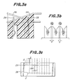
- connection wire 3A to be connected to a contact tail 2A in a first row and a connection wire 3B to be connected to 16 a contact tail 2B in a second row are arranged in directions reverse relative to each other downwardly toward contact tails to connected, respectively, as shown in Fig. 3a.
- connection wire holding inclined surfaces whose inclinations are so determined that the connection wire 3B to be connected to the contact tail 2B in the second row is arranged above the uppermost end of the contact tail 2A in the first row and the connection wire 3A to be connected to the contact tail 2A in first row is arrange above the uppermost end of the contact tail 2B in the second row.
- connection wires 3A and 3B can be connected to contact tails without passing between contact tails 2B and 2A in the other row, thereby reducing distances 1 between the contact tails to a minimum possible distance without detrimentally affecting the insulation between wires as shown in Figs. 3b and 3c. In this manner, a further miniaturization of connector is accomplished.
- Figs. 4a and 4b illustrating one embodiment of the invention are a perspective view of a non-pierced condition and a sectional side view of pierced condition.
- Fig. 4a illustrates a connector body A made of an insulating contact support block 1, contact tails 2A and 2B in first and second rows, and first and second support bases 4A and 4B for obliquely arranging connection wires.
- the first and second support bases 4A and 4B are alternately arranged.
- the first support base 4A has an inclination directing downwardly toward the contact tails 2A in the first row, while the second support base 4B has an inclination directing downwardly toward the contact tails 2B in the second row.
- the inclinations of the first and second support bases 4A and 4B are so selected that surfaces of the first and second support bases 4A and 4B corresponding to uppermost ends of the contact tails 2A and 2B in the first and second rows are located above the uppermost ends of the contact tails 2A and 2B.
- a cover B comprises an insulating block 6 having positioning walls 6a for positioning the cover B relative to the connector body A, and U-shaped locking members 7 adapted to be engaged with the locking protrusions 5 of the connector body A.
- First and second push bases 8A and 8B for obliquely arranging the connection wires are alternately arranged and have inclinations which are in parallel with and reversely inclined to that of the inclinations of the connector body A so that the connection wires are embraced between the inclinations of the connector body A and the cover B when the cover B is connected to the connector body A by means of the locking protrusions 5 and the U-shaped locking members 7.
- the cover B is formed with contact tail receiving grooves 9A and 9B for receiving the contact tails 2A and 2B when the cover B is connected to the connector body as shown in Fig. 4c.
- connection wires 3A and 3B have been arrange on the first and second support bases 4A and 4B of the connector body A as shown in Fig. 4b
- the cover B is arranged and locked onto the connector body A such that surfaces of the inclinations of the first and second push bases 8A and 8B of the cover B are aligned with surfaces of the inclinations of the first and second support bases 4A and 4B of the connector body B and the contact tails 2A and 2B are brought into the contact tail receiving grooves 9A and 9B.
- connection wires 3A are pressed into pressing slits 2a of the contact tails 2A in the first row so as to be connected to the contact tails 2A
- connection wires 3B are pressed into pressing slits 2a of the contact tails 2B in the second row so as to be connected to the contact tails 2B as shown in Fig. 4c.
- the connection wires 3A are positioned above the uppermost ends of the contact tails 2B in the second row and the connection wires 3B are positioned above the uppermost ends of the contact tails 2A in the first row, while these connection wires 3A and 3B are embraced and held between the support bases 4A and 4B and push bases 8A and 8B.
- connection wires do not extend between the contact trails, so that distances between the contact tails can be shortened to accomplish the miniaturization of the connector.
- the connector according to the invention can be applicable to a flat cable which, for example, comprises a number of bare wires 10 arranged in parallel with predetermined intervals and coated with a resin insulating material 11 to form a flat cable 12 as shown in Fig. 5.
- a flat cable 12 which, for example, comprises a number of bare wires 10 arranged in parallel with predetermined intervals and coated with a resin insulating material 11 to form a flat cable 12 as shown in Fig. 5.
- the cover B is forced onto the connector body A.
- the coating 11 between the bare wires 10 is pierced with the contact tails 2A and 2B so that the bare wires enter bottoms between the support bases 4A and 4B to be settled onto the inclinations of the connector body A and the cover B, whereby connection of the flat cable is established.
- a cover B is divided into two parts B1 and B2, of which one B1 is provided with first and second support bases 4A and 4B having contact tail passing-through apertures 13A and 13B and the other B2 is provided with first and second push bases 8A and 8B having contact tail receiving grooves 9A and 9B.
- the cover parts B1 and B2 are covered on a connector body A such that contact tails 2A and 2B embedded in the connector body A are inserted into the contact tail passing-through apertures 13A and 13B, whereby a piercing connection is established.
- the connector body A and the cover part B of insulating blocks may be previously connected together as a unitary body to form the connector body A in the first embodiment so that this embodiment becomes substantially the same as the first embodiment.
- the surfaces of the support bases 4A and 4B and push bases 8A and 8B for arranging the connection wires are substantially flat so that there is a risk for the connection wires to fall from the surfaces of the support bases 4A and 4B into the bottoms between the support bases when the connection wires are pushed by the push bases 8A and 8B. Therefore, the proper connection cannot be often accomplished.
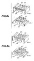
- connection wire positioning recesses 4A1, 4B1, 8A1 and 8B1 are provided in the proximities of the uppermost portions of the inclined surfaces of the support bases 4A and 4B and/or the push bases 8A and 8B.
- elongated supporting grooves 4A1, 4B1, 8A1 and 8B1 are provided along the inclinations of the support bases 4A and 4B and/or the push bases 8A and 8B.
- uppermost ends of the inclination surfaces may be chamfered to prevent wires from being damaged by sharp edges of the uppermost ends of the inclination surfaces.
- the support bases 4A and 4B and the push bases 8A and 8B are provided at their highest portions with triangular or semicircular piercing assisting projections 4A2, 4B2 and 8A2, 8B2 so that torn lengths of the coating 11 of the flat cable 12 are made much longer in order to make easy the piercing by contact tails as shown in Figs. 9a and 9b.
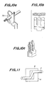
- the invention is applicable to other conventional contacts, for example, a contact having a tubular tail formed with a pressing slit 2a as shown in Figs. 10a, 10b and 10c.
- the inclination surfaces of the support bases 4A and 4B and push bases 8A and 8B may be like steps as shown in Fig. 11 although they are not preferable.
- connection wires 3 are folded along the steps so that the wires are pulled by folded lengths of the wires. Therefore, there are risks for contact tails to be subjected to tensile forces or deformed or for connection wires to be damaged.
- Fig. 12 illustrates a further embodiment.
- contact tails have been explained arranged in two rows.
- alternately inclined support bases 3C and 3D are alternately arranged and the contact tails 2A1 and 2A2 are so fixed that centers of the contact tails are at the support bases 3D inclined in the same direction and the contact tails 2B1 and 2B2 are fixed so as to be shifted by a width of one of the support bases relative to the contact tails so that within the width of one contact tail are included the two support bases 3D inclined in the same direction and one support base 3C therebetween.
- the inclinations and angles thereof of the support bases 3C and 3D are so determined that with respect to one connection wire, one contact tail to be connected to the wire is extended over one support base, but the other contact tails do not extend over the two support bases 3C and 3D.
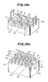
- FIG. 14a is a perspective view of a connector body A
- Fig. 14b is a perspective view of a cover B thereof.
- a contact support block 1 comprises locking protrusions 14A, support bases 3C and support bases 3D having inclinations inclined in reverse directions to those of the support bases 3C.
- Reference numeral 2 denotes contact tails.
- the tails 2A1 and 2A2 are fixed in the support block 1 in two rows and staggered such that one tail in one row is located between two adjacent tails in the other row and the tails 2B1 and 2B2 are also fixed in the support block 1 in two rows and staggered such that one tail in one row is located between two adjacent tails in the other row.
- tails 2A1 and 2A2 are shifted by the width of the support base relative to the tails 2B1 and 2B2.
- a cover B has U-shaped locking member 14B and push bases 3E and 3F inclined in directions reverse to those of the support bases 3C and 3D.
- the push bases 3E and 3F are formed with contact tail receiving grooves 5 for receiving the contact tails.
- connection wires 3A and 3B are forced into the contact tail pressing slits 2a so as to be connected to the contacts and embraced between the support bases 3C, 3E, 3D and 3F to prevent the connection wires from removing therefrom.
- the insulation-piercing connector having contact tails staggered in two rows capable of leading out connection wires arranged above contact tails arranged in opposition to contact tails to which the wires are connected, so that distances between the adjacent contact tails can be shortened in comparison with those of the prior art.
- the miniaturization of the connector can be accomplished which can eliminate the risk of the connection wires to be damaged caused by contacting of the wires with contact tails.
Landscapes
- Multi-Conductor Connections (AREA)
- Coupling Device And Connection With Printed Circuit (AREA)
- Connections By Means Of Piercing Elements, Nuts, Or Screws (AREA)
Applications Claiming Priority (4)
| Application Number | Priority Date | Filing Date | Title |
|---|---|---|---|
| JP197170/87U | 1987-12-25 | ||
| JP1987197170U JPH0546218Y2 (fr) | 1987-12-25 | 1987-12-25 | |
| JP63253419A JPH02100274A (ja) | 1988-10-07 | 1988-10-07 | 圧接形コネクタ |
| JP253419/88 | 1988-10-07 |
Publications (3)
| Publication Number | Publication Date |
|---|---|
| EP0323340A2 true EP0323340A2 (fr) | 1989-07-05 |
| EP0323340A3 EP0323340A3 (en) | 1990-07-11 |
| EP0323340B1 EP0323340B1 (fr) | 1994-03-23 |
Family
ID=26510208
Family Applications (1)
| Application Number | Title | Priority Date | Filing Date |
|---|---|---|---|
| EP88403320A Expired - Lifetime EP0323340B1 (fr) | 1987-12-25 | 1988-12-23 | Connecteur à percement d'isolation |
Country Status (4)
| Country | Link |
|---|---|
| US (1) | US4948381A (fr) |
| EP (1) | EP0323340B1 (fr) |
| CA (1) | CA1292292C (fr) |
| DE (1) | DE3888662T2 (fr) |
Cited By (6)
| Publication number | Priority date | Publication date | Assignee | Title |
|---|---|---|---|---|
| EP0449743A1 (fr) * | 1990-03-29 | 1991-10-02 | Daiichi Denshi Kogyo Kabushiki Kaisha | Connecteur à percement d'isolation |
| US5358424A (en) * | 1993-08-11 | 1994-10-25 | Molex Incorporated | Electrical connector for high density ribbon cable |
| WO1996008852A1 (fr) * | 1994-09-13 | 1996-03-21 | Mod-Tap W Corporation | Connecteur autodenudant |
| EP0632541A3 (fr) * | 1993-06-09 | 1996-05-22 | Molex Inc | Connecteur électrique pour câble plat à haute densité. |
| US5997338A (en) * | 1993-12-01 | 1999-12-07 | Oy Iws International Inc. | Conductor joint for connecting an intelligent socket to a cable |
| EP1178571A3 (fr) * | 2000-07-31 | 2002-04-03 | FINCANTIERI CANTIERI NAVALI ITALIANI S.p.A. | Améliorations de dispositifs et procédés pour la distribution d'électricité et de signaux, en particulier dans le domaine naval |
Families Citing this family (3)
| Publication number | Priority date | Publication date | Assignee | Title |
|---|---|---|---|---|
| DE10319728A1 (de) * | 2003-04-30 | 2004-11-18 | Wago Verwaltungsgesellschaft Mbh | Abzweig-Steckverbinder |
| JP6614051B2 (ja) * | 2016-07-12 | 2019-12-04 | 株式会社オートネットワーク技術研究所 | 電気接続アセンブリの製造方法 |
| CN117080761A (zh) * | 2023-08-24 | 2023-11-17 | 深圳市锦凌电子有限公司 | 刺破型电连接器 |
Family Cites Families (8)
| Publication number | Priority date | Publication date | Assignee | Title |
|---|---|---|---|---|
| DE2522755C2 (de) * | 1975-05-22 | 1982-10-28 | Siemens AG, 1000 Berlin und 8000 München | Löthilfe zum Verbinden von Flachbandkabeln mit Leiterplatten |
| US4026625A (en) * | 1975-11-10 | 1977-05-31 | Minnesota Mining And Manufacturing Company | Universal connector |
| US4009922A (en) * | 1975-11-10 | 1977-03-01 | Minnesota Mining And Manufacturing Company | Connector |
| US4068912A (en) * | 1977-02-25 | 1978-01-17 | Amp Incorporated | Cable clamping insulation displacing electrical connector for multi-conductor flat flexible cable |
| JPS5514652A (en) * | 1978-07-19 | 1980-02-01 | Yamaichi Electric Mfg | Electric terminal |
| US4444450A (en) * | 1982-01-28 | 1984-04-24 | Amp Incorporated | Flat transmission cable connector and housing therefor |
| US4693539A (en) * | 1983-12-27 | 1987-09-15 | Amp Incorporated | Ribbon coax cable connector |
| US4641903A (en) * | 1983-12-27 | 1987-02-10 | International Telephone And Telegraph Corporation | Insulation displacement connector |
-
1988
- 1988-12-20 US US07/287,383 patent/US4948381A/en not_active Expired - Lifetime
- 1988-12-21 CA CA000586612A patent/CA1292292C/fr not_active Expired - Fee Related
- 1988-12-23 DE DE3888662T patent/DE3888662T2/de not_active Expired - Fee Related
- 1988-12-23 EP EP88403320A patent/EP0323340B1/fr not_active Expired - Lifetime
Cited By (8)
| Publication number | Priority date | Publication date | Assignee | Title |
|---|---|---|---|---|
| EP0449743A1 (fr) * | 1990-03-29 | 1991-10-02 | Daiichi Denshi Kogyo Kabushiki Kaisha | Connecteur à percement d'isolation |
| US5120244A (en) * | 1990-03-29 | 1992-06-09 | Daiichi Denshi Kogyo Kabushiki Kaisha | Insulation-piercing connector |
| EP0632541A3 (fr) * | 1993-06-09 | 1996-05-22 | Molex Inc | Connecteur électrique pour câble plat à haute densité. |
| US5358424A (en) * | 1993-08-11 | 1994-10-25 | Molex Incorporated | Electrical connector for high density ribbon cable |
| US5997338A (en) * | 1993-12-01 | 1999-12-07 | Oy Iws International Inc. | Conductor joint for connecting an intelligent socket to a cable |
| WO1996008852A1 (fr) * | 1994-09-13 | 1996-03-21 | Mod-Tap W Corporation | Connecteur autodenudant |
| US6042415A (en) * | 1994-09-13 | 2000-03-28 | Molex Incorporated | Insulation displacement connector |
| EP1178571A3 (fr) * | 2000-07-31 | 2002-04-03 | FINCANTIERI CANTIERI NAVALI ITALIANI S.p.A. | Améliorations de dispositifs et procédés pour la distribution d'électricité et de signaux, en particulier dans le domaine naval |
Also Published As
| Publication number | Publication date |
|---|---|
| US4948381A (en) | 1990-08-14 |
| CA1292292C (fr) | 1991-11-19 |
| DE3888662D1 (de) | 1994-04-28 |
| EP0323340A3 (en) | 1990-07-11 |
| EP0323340B1 (fr) | 1994-03-23 |
| DE3888662T2 (de) | 1994-07-07 |
Similar Documents
| Publication | Publication Date | Title |
|---|---|---|
| US4743208A (en) | Pin grid array electrical connector | |
| US4484791A (en) | Connector for multiconductor flat insulated cable | |
| EP0043165A1 (fr) | Connecteur en boîte | |
| EP0496287B1 (fr) | Terminal pour panneaux, pénétrant dans l'isolation et la déplaçant | |
| EP0018382A4 (fr) | Connecteur electrique. | |
| EP0242019A2 (fr) | Connecteur pour communications | |
| US5897394A (en) | Conductor connection terminal and method of connection | |
| US4948381A (en) | Insulation-piercing connector | |
| JP2001267023A (ja) | モジュラープラグ及びハーネス品 | |
| US2794964A (en) | Electric wire connector | |
| US3768062A (en) | Terminal for flexible circuits | |
| JPH05144484A (ja) | 絶縁排除式接触子及びこれを使用したコネクタ | |
| EP0717461B1 (fr) | Connecteur électrique de dérivation à déplacement d'isolation pour câbles de différentes tailles | |
| US4380119A (en) | Method of making an electrical connector assembly | |
| US5120244A (en) | Insulation-piercing connector | |
| JPS60221977A (ja) | ケ−ブル終端用コネクタ | |
| US4600259A (en) | Electrical terminal having wire-receiving slot for relatively small diameter wires and connectors containing such terminals | |
| US5928030A (en) | Bridging clip for wire wrapped terminals | |
| EP0123417A2 (fr) | Câble-ruban électrique sans entailles | |
| US5052945A (en) | Contact for connection of a shielded wire | |
| EP0203013A2 (fr) | Connecteur à contacts multiples muni d'un bloc formant borne de mise à la terre connecté à des conducteurs en ruban et procédé pour connecter des conducteurs en ruban à un connecteur à contacts multiples | |
| CA1139387A (fr) | Contact electrique denudeur et methode de fabrication | |
| JP2003016850A (ja) | フラット回路体およびその製造方法 | |
| JP3179213B2 (ja) | 連鎖端子 | |
| GB2100074A (en) | Wire connector |
Legal Events
| Date | Code | Title | Description |
|---|---|---|---|
| PUAI | Public reference made under article 153(3) epc to a published international application that has entered the european phase |
Free format text: ORIGINAL CODE: 0009012 |
|
| AK | Designated contracting states |
Kind code of ref document: A2 Designated state(s): DE FR GB |
|
| PUAL | Search report despatched |
Free format text: ORIGINAL CODE: 0009013 |
|
| AK | Designated contracting states |
Kind code of ref document: A3 Designated state(s): DE FR GB |
|
| 17P | Request for examination filed |
Effective date: 19901215 |
|
| 17Q | First examination report despatched |
Effective date: 19920827 |
|
| GRAA | (expected) grant |
Free format text: ORIGINAL CODE: 0009210 |
|
| AK | Designated contracting states |
Kind code of ref document: B1 Designated state(s): DE FR GB |
|
| REF | Corresponds to: |
Ref document number: 3888662 Country of ref document: DE Date of ref document: 19940428 |
|
| ET | Fr: translation filed | ||
| PGFP | Annual fee paid to national office [announced via postgrant information from national office to epo] |
Ref country code: FR Payment date: 19941118 Year of fee payment: 7 |
|
| PGFP | Annual fee paid to national office [announced via postgrant information from national office to epo] |
Ref country code: DE Payment date: 19941202 Year of fee payment: 7 |
|
| PGFP | Annual fee paid to national office [announced via postgrant information from national office to epo] |
Ref country code: GB Payment date: 19941213 Year of fee payment: 7 |
|
| PLBE | No opposition filed within time limit |
Free format text: ORIGINAL CODE: 0009261 |
|
| STAA | Information on the status of an ep patent application or granted ep patent |
Free format text: STATUS: NO OPPOSITION FILED WITHIN TIME LIMIT |
|
| 26N | No opposition filed | ||
| PG25 | Lapsed in a contracting state [announced via postgrant information from national office to epo] |
Ref country code: GB Effective date: 19951223 |
|
| GBPC | Gb: european patent ceased through non-payment of renewal fee |
Effective date: 19951223 |
|
| PG25 | Lapsed in a contracting state [announced via postgrant information from national office to epo] |
Ref country code: FR Effective date: 19960830 |
|
| PG25 | Lapsed in a contracting state [announced via postgrant information from national office to epo] |
Ref country code: DE Effective date: 19960903 |
|
| REG | Reference to a national code |
Ref country code: FR Ref legal event code: ST |