EP0323412A2 - Zündungsystem für innere Brennkraftmaschinen von Fahrzeugen, insbesondere vom statischen Verteilertyp - Google Patents
Zündungsystem für innere Brennkraftmaschinen von Fahrzeugen, insbesondere vom statischen Verteilertyp Download PDFInfo
- Publication number
- EP0323412A2 EP0323412A2 EP88830500A EP88830500A EP0323412A2 EP 0323412 A2 EP0323412 A2 EP 0323412A2 EP 88830500 A EP88830500 A EP 88830500A EP 88830500 A EP88830500 A EP 88830500A EP 0323412 A2 EP0323412 A2 EP 0323412A2
- Authority
- EP
- European Patent Office
- Prior art keywords
- switching
- transistor
- control circuit
- ignition
- ignition system
- Prior art date
- Legal status (The legal status is an assumption and is not a legal conclusion. Google has not performed a legal analysis and makes no representation as to the accuracy of the status listed.)
- Withdrawn
Links
Images

Classifications
-
- F—MECHANICAL ENGINEERING; LIGHTING; HEATING; WEAPONS; BLASTING
- F02—COMBUSTION ENGINES; HOT-GAS OR COMBUSTION-PRODUCT ENGINE PLANTS
- F02P—IGNITION, OTHER THAN COMPRESSION IGNITION, FOR INTERNAL-COMBUSTION ENGINES; TESTING OF IGNITION TIMING IN COMPRESSION-IGNITION ENGINES
- F02P3/00—Other installations
- F02P3/02—Other installations having inductive energy storage, e.g. arrangements of induction coils
- F02P3/04—Layout of circuits
- F02P3/045—Layout of circuits for control of the dwell or anti dwell time
- F02P3/0453—Opening or closing the primary coil circuit with semiconductor devices
-
- F—MECHANICAL ENGINEERING; LIGHTING; HEATING; WEAPONS; BLASTING
- F02—COMBUSTION ENGINES; HOT-GAS OR COMBUSTION-PRODUCT ENGINE PLANTS
- F02P—IGNITION, OTHER THAN COMPRESSION IGNITION, FOR INTERNAL-COMBUSTION ENGINES; TESTING OF IGNITION TIMING IN COMPRESSION-IGNITION ENGINES
- F02P7/00—Arrangements of distributors, circuit-makers or -breakers, e.g. of distributor and circuit-breaker combinations or pick-up devices
- F02P7/02—Arrangements of distributors, circuit-makers or -breakers, e.g. of distributor and circuit-breaker combinations or pick-up devices of distributors
- F02P7/03—Arrangements of distributors, circuit-makers or -breakers, e.g. of distributor and circuit-breaker combinations or pick-up devices of distributors with electrical means
-
- F—MECHANICAL ENGINEERING; LIGHTING; HEATING; WEAPONS; BLASTING
- F02—COMBUSTION ENGINES; HOT-GAS OR COMBUSTION-PRODUCT ENGINE PLANTS
- F02P—IGNITION, OTHER THAN COMPRESSION IGNITION, FOR INTERNAL-COMBUSTION ENGINES; TESTING OF IGNITION TIMING IN COMPRESSION-IGNITION ENGINES
- F02P9/00—Electric spark ignition control, not otherwise provided for
- F02P9/002—Control of spark intensity, intensifying, lengthening, suppression
Definitions
- the present invention relates to an ignition system for an internal combustion engine, particularly of the static-distribution type, in which a respective ignition coil with a primary winding and a secondary winding is coupled to the sparking plug associated with each cylinder, the system including a switching transistor for each ignition coil and control circuit means which, in order to generate a spark in a plug, are adapted to cause a first switching of the corresponding transistor from the shut-off condition to the conducting condition to start the flow of current in the primary winding of the associated coil, and a second switching to the shut-off condition to stop the flow of current in the primary winding of the coil, causing the striking of the spark.
- FIG. 1 An ignition system of this type is schematically illustrated in Figure 1.
- the system illustrated includes a sensor 1 of known type for providing electrical signals indicative of the angular position and of the rate of rotation of the shaft of an internal combustion engine, not illustrated.
- This sensor is connected to an electronic microprocessor control unit 4 of known type, to which further sensors, such as, for example, a sensor 2 for sensing the vacuum in the intake manifold of the engine, a sensor 3 for sensing the temperature of the air taken in by the engine, etc., are also connected.
- the unit 4 is arranged to cause, in a predetermined manner, the generation of sparks in sparking plugs SP through respective ignition coils C piloted by power switching transistors T, for example of the Darlington type.
- each coil C comprises a primary winding 5 connected in series with the collector-emitter path of a transistor T, between a direct voltage supply V B (the battery of the motor vehicle) and earth.
- Each coil also includes a secondary winding, indicated 6, coupled to the respective plug SP.
- the unit 4 causes the cyclical application of operating signals to the bases of the transistors T in dependence on the signals provided by the sensors 1 to 3, to cause the generation of the sparks in the various cylinders of the engine with the necessary advance.
- the unit 4 applies a signal to the base of the corresponding transistor T so as to cause a first switching of the transistor from the shut-off condition to the conducting condition to start the flow of current in the primary winding 5 of the associated coil C.
- the unit 4 causes a second switching of the transistor to the shut-off condition to stop the flow of current in the primary winding of the associated coil and to cause the striking of the spark in the corresponding plug.
- the trace of the voltage V ce between the collector and the emitter of the transistor T correspondingly follows the trace illustrated in Figure 2, in which the times t0 and t1 correspond to the two switchings described above.
- the trace of the intensity of the current flowing in the primary winding and in the ignition coil and the trace of the voltage applied to the plug are correspondingly indicated I c and V sp in the same drawing.
- the voltage V sp has a peak value P1 which corresponds substantially with the time t0.
- This voltage peak can in fact reach values of 2,000-3,000 V.
- the voltage V sp then has a second peak P2 which corresponds substantially with the time t1; this peak is the one which is actually intended to generate the spark.
- the amplitude of the spurious peak P1 may in some circumstances be sufficient to generate a spark which, in such a case, is decidedly out of phase.
- the object of the present invention is to produce an ignition system of the type specified above, in which the problem relating to the spurious voltage peak associated with the first switching of the transistors piloting the coils is effectively resolved at source.
- control circuit means are arranged to control the speed of the first switching of the transistor or transistors concerned from time to time, for each ignition, so that the first switching takes place gradually at a speed less than a predetermined value.
- control circuit means for each switching transistor comprise a control circuit loop which is arranged to detect the voltage between the collector and the emitter during the first switching and to modify the base current of the controlled transistor so that the voltage between the collector and the emitter varies gradually in a predetermined manner.
- the electronic control and operating unit of the ignition system is arranged to pilot each switching transistor so that a pulsed operating voltage is applied to the base of the transistor concerned from time to time, with a duty cycle which increases gradually in a predetermined manner with rise and fall times which are less than the switching time of the transistor.
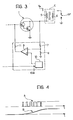
- FIG 3 shows part of an ignition system according to Figure 1 which relates to the control of the striking of the spark in a plug SP.
- this drawing shows a switching transistor T constituted by a pair of individual transistors connected in a Darlington arrangement with their common collector connected to the primary winding 5 of the coil C and their emitter connected to earth.
- a resistive divider formed by two resistors 7 and 8 is connected to the collector of the transistor T.
- This divider is connected to the inverting input of a differential amplifier 9 to the non-inverting input of which the output of a ramp generator 10 is connected.
- This generator has a control input 10a connected to an output of the microprocesor unit 4.
- the output of the differential amplifier 9 is connected to the base of the transistor T through a resistor 11.
- the microprocessor unit 4 provides a voltage to its base to cause it to switch from the shut-off condition to the conducting condition.
- the ramp generator 10 is activated.
- the differential amplifier 9 adjusts the current provided to the base of the transistor T so that the voltage between the collector and the emitter of the transistor varies substantially according to the law of variation of the ramp signal generated by the circuit 10. Conveniently, this law of variation is sufficiently slow that the spurious pulse which appears (by differential effect) in the voltage provided at the output of the coil C has an amplitude less than a predetermined value and therefore not sufficient to enable a spark to be struck.
- the ignition system according to the invention retains substantially the same structure as that illustrated in Figure 1 but the electronic control and operating unit 4 is arranged, in known manner, to apply to each switching transistor (each time the first switching is to be carried out) a pulsed operating voltage with a gradually increasing duty cycle, as illustrated qualitatively by the signal indicated A in Figure 4.
- the rise and fall times of the pulses of the signal A must be less than the switching time of the transistors T so that, in practice, the bases of the transistors "experience" the application of a signal having the qualitative trace indicated B in the same Figure 4.
- the gradual variation in the base voltage of the transistors corresponds to the gradual variation in their collector-emitter voltage and the amplitude of the corresponding spurious peaks of the voltage provided at the output of the coil C is reduced.
Landscapes
- Engineering & Computer Science (AREA)
- Chemical & Material Sciences (AREA)
- Combustion & Propulsion (AREA)
- Mechanical Engineering (AREA)
- General Engineering & Computer Science (AREA)
- Ignition Installations For Internal Combustion Engines (AREA)
Applications Claiming Priority (2)
| Application Number | Priority Date | Filing Date | Title |
|---|---|---|---|
| IT6813987 | 1987-12-29 | ||
| IT8768139A IT1212156B (it) | 1987-12-29 | 1987-12-29 | Sistema di accensione per un motore a combustione interna per autoveicoli in particolare del tipo a distribuzione statica |
Publications (2)
| Publication Number | Publication Date |
|---|---|
| EP0323412A2 true EP0323412A2 (de) | 1989-07-05 |
| EP0323412A3 EP0323412A3 (de) | 1990-04-04 |
Family
ID=11308107
Family Applications (1)
| Application Number | Title | Priority Date | Filing Date |
|---|---|---|---|
| EP88830500A Withdrawn EP0323412A3 (de) | 1987-12-29 | 1988-11-22 | Zündungsystem für innere Brennkraftmaschinen von Fahrzeugen, insbesondere vom statischen Verteilertyp |
Country Status (5)
| Country | Link |
|---|---|
| EP (1) | EP0323412A3 (de) |
| JP (1) | JPH01177453A (de) |
| BR (1) | BR8805523A (de) |
| IT (1) | IT1212156B (de) |
| PT (1) | PT88892A (de) |
Cited By (8)
| Publication number | Priority date | Publication date | Assignee | Title |
|---|---|---|---|---|
| EP0458762A1 (de) * | 1990-05-23 | 1991-11-27 | FIAT AUTO S.p.A. | Zündanlage für innere Brennkraftmaschinen, insbesondere zur Detektion von Zündfunken-Aussetzern |
| WO1994013950A1 (en) * | 1992-12-09 | 1994-06-23 | Sydney Gilbert Hodgins | Internal combustion engine with low voltage distribution |
| DE19612201A1 (de) * | 1995-03-31 | 1996-10-02 | Mitsubishi Electric Corp | Zündvorrichtung für eine Brennkraftmaschine |
| DE19741963C1 (de) * | 1997-09-23 | 1999-03-11 | Siemens Ag | Vorrichtung zur Unterdrückung unerwünschter Zündungen bei einem Ottomotor |
| DE19741439A1 (de) * | 1997-09-19 | 1999-03-25 | Bayerische Motoren Werke Ag | Vorrichtung und Verfahren zum Einschalten des Primärstroms einer Zündspule |
| DE102004013561A1 (de) * | 2004-03-19 | 2005-10-13 | Audi Ag | Verfahren und Schaltvorrichtung zum Betreiben einer Zündspule eines Kraftfahrzeugs |
| DE10130474B4 (de) * | 2000-07-03 | 2005-11-03 | Delphi Technologies, Inc., Troy | Kraftfahrzeugzündsystem mit anpaßbarer Nachschwingdämpfung bei Beginn der Wartezeit |
| DE10109853B4 (de) * | 2000-03-03 | 2008-04-10 | Hitachi, Ltd. | Zündvorrichtung für Brennkraftmaschine und Einchip-Halbleiter für Brennkraftmaschinen-Zündung |
Families Citing this family (1)
| Publication number | Priority date | Publication date | Assignee | Title |
|---|---|---|---|---|
| CN105943153B (zh) * | 2016-05-08 | 2019-03-15 | 苏州诺来宁医疗科技有限公司 | 一种外科用自动拧钉装置 |
Family Cites Families (5)
| Publication number | Priority date | Publication date | Assignee | Title |
|---|---|---|---|---|
| FR2157024A5 (de) * | 1971-10-14 | 1973-06-01 | Fime Sa | |
| US3940658A (en) * | 1973-12-26 | 1976-02-24 | Superior Industries, Inc. | Electronic ignition control system |
| JPS6053795B2 (ja) * | 1978-03-14 | 1985-11-27 | 株式会社デンソー | 内燃機関点火装置 |
| DE3120695A1 (de) * | 1981-05-23 | 1982-12-09 | Robert Bosch Gmbh, 7000 Stuttgart | "schaltungsanordnung mit einem endtransistor zum ein- und ausschalten eines verbrauchers, insbesondere der primaerwicklung einer zu der zuendanlage einer brennkraftmaschine gehoerenden zuendspule" |
| DE3334833A1 (de) * | 1983-09-27 | 1985-04-04 | Telefunken electronic GmbH, 7100 Heilbronn | Ansteuerschaltung fuer einen leistungstransistor |
-
1987
- 1987-12-29 IT IT8768139A patent/IT1212156B/it active
-
1988
- 1988-10-25 JP JP63269279A patent/JPH01177453A/ja active Pending
- 1988-10-27 BR BR8805523A patent/BR8805523A/pt unknown
- 1988-10-28 PT PT88892A patent/PT88892A/pt not_active Application Discontinuation
- 1988-11-22 EP EP88830500A patent/EP0323412A3/de not_active Withdrawn
Cited By (11)
| Publication number | Priority date | Publication date | Assignee | Title |
|---|---|---|---|---|
| EP0458762A1 (de) * | 1990-05-23 | 1991-11-27 | FIAT AUTO S.p.A. | Zündanlage für innere Brennkraftmaschinen, insbesondere zur Detektion von Zündfunken-Aussetzern |
| US5115793A (en) * | 1990-05-23 | 1992-05-26 | Fiat Auto Spa | Ignition device for internal combustion engines, particularly for detecting spark failure |
| WO1994013950A1 (en) * | 1992-12-09 | 1994-06-23 | Sydney Gilbert Hodgins | Internal combustion engine with low voltage distribution |
| DE19612201A1 (de) * | 1995-03-31 | 1996-10-02 | Mitsubishi Electric Corp | Zündvorrichtung für eine Brennkraftmaschine |
| DE19741439A1 (de) * | 1997-09-19 | 1999-03-25 | Bayerische Motoren Werke Ag | Vorrichtung und Verfahren zum Einschalten des Primärstroms einer Zündspule |
| DE19741963C1 (de) * | 1997-09-23 | 1999-03-11 | Siemens Ag | Vorrichtung zur Unterdrückung unerwünschter Zündungen bei einem Ottomotor |
| US6257216B1 (en) | 1997-09-23 | 2001-07-10 | Siemens Aktiengesellschaft | Device for suppressing undesired ignitions in a spark ignition engine |
| DE10109853B4 (de) * | 2000-03-03 | 2008-04-10 | Hitachi, Ltd. | Zündvorrichtung für Brennkraftmaschine und Einchip-Halbleiter für Brennkraftmaschinen-Zündung |
| DE10130474B4 (de) * | 2000-07-03 | 2005-11-03 | Delphi Technologies, Inc., Troy | Kraftfahrzeugzündsystem mit anpaßbarer Nachschwingdämpfung bei Beginn der Wartezeit |
| DE102004013561A1 (de) * | 2004-03-19 | 2005-10-13 | Audi Ag | Verfahren und Schaltvorrichtung zum Betreiben einer Zündspule eines Kraftfahrzeugs |
| DE102004013561B4 (de) * | 2004-03-19 | 2007-02-22 | Audi Ag | Verfahren und Schaltvorrichtung zum Betreiben einer Zündspule eines Kraftfahrzeugs |
Also Published As
| Publication number | Publication date |
|---|---|
| JPH01177453A (ja) | 1989-07-13 |
| IT1212156B (it) | 1989-11-08 |
| IT8768139A0 (it) | 1987-12-29 |
| BR8805523A (pt) | 1989-07-04 |
| PT88892A (pt) | 1989-09-14 |
| EP0323412A3 (de) | 1990-04-04 |
Similar Documents
| Publication | Publication Date | Title |
|---|---|---|
| US5127388A (en) | Ignition system for an internal combustion engine | |
| IT1208855B (it) | Sistema di accensione ad energia di scintilla variabile per motori acombustione interna particolarmente per autoveicoli | |
| US4404940A (en) | Engine speed limiting circuit | |
| US4128091A (en) | Hall effect electronic ignition controller with programmed dwell and automatic shut-down timer circuits | |
| US4138977A (en) | Ignition system for internal combustion engine | |
| US4285323A (en) | Transistorized ignition apparatus for driving ignition coils in an internal combustion engine | |
| JPH0421013Y2 (de) | ||
| US4217872A (en) | Multiple spark ignition system for an internal combustion engine | |
| US3749974A (en) | Electronic ignition controller | |
| US4084567A (en) | Contactless ignition system for internal combustion engine | |
| US3241538A (en) | Electronic ignition system | |
| JPH01177453A (ja) | 内燃エンジン点火装置 | |
| ES445284A1 (es) | Perfeccionamientos en los sistemas de proteccion de disposi-tivos de encendido para vehiculos automoviles. | |
| US4100908A (en) | Semiconductor ignition system for internal combustion engines | |
| US4528972A (en) | Emergency ignition device for thermal engines with controlled ignition | |
| US4030469A (en) | Electronic ignition circuit | |
| JPS6054510B2 (ja) | 内燃機関用点火装置 | |
| US4799471A (en) | Electronic system for controlling the ignition of an internal combustion engine, particularly for motor vehicles | |
| US3626912A (en) | Device for regulating the supply of carburant to an internal combustion engine | |
| US3253163A (en) | Semiconductor internal combustion engine ignition system | |
| JPH0828415A (ja) | 内燃機関用点火装置 | |
| JPH0579826B2 (de) | ||
| JP2519574B2 (ja) | 内燃機関の点火装置 | |
| JPS647065Y2 (de) | ||
| JPH02241987A (ja) | 内燃機関の点火装置 |
Legal Events
| Date | Code | Title | Description |
|---|---|---|---|
| PUAI | Public reference made under article 153(3) epc to a published international application that has entered the european phase |
Free format text: ORIGINAL CODE: 0009012 |
|
| AK | Designated contracting states |
Kind code of ref document: A2 Designated state(s): AT BE CH DE ES FR GB GR IT LI LU NL SE |
|
| PUAL | Search report despatched |
Free format text: ORIGINAL CODE: 0009013 |
|
| RHK1 | Main classification (correction) |
Ipc: F02P 3/045 |
|
| AK | Designated contracting states |
Kind code of ref document: A3 Designated state(s): AT BE CH DE ES FR GB GR IT LI LU NL SE |
|
| STAA | Information on the status of an ep patent application or granted ep patent |
Free format text: STATUS: THE APPLICATION IS DEEMED TO BE WITHDRAWN |
|
| 18D | Application deemed to be withdrawn |
Effective date: 19901005 |