EP0323601B1 - Détecteur à radiations - Google Patents
Détecteur à radiations Download PDFInfo
- Publication number
- EP0323601B1 EP0323601B1 EP88121211A EP88121211A EP0323601B1 EP 0323601 B1 EP0323601 B1 EP 0323601B1 EP 88121211 A EP88121211 A EP 88121211A EP 88121211 A EP88121211 A EP 88121211A EP 0323601 B1 EP0323601 B1 EP 0323601B1
- Authority
- EP
- European Patent Office
- Prior art keywords
- housing
- guide channel
- detector according
- masking element
- frame
- Prior art date
- Legal status (The legal status is an assumption and is not a legal conclusion. Google has not performed a legal analysis and makes no representation as to the accuracy of the status listed.)
- Expired - Lifetime
Links
Images

Classifications
-
- G—PHYSICS
- G08—SIGNALLING
- G08B—SIGNALLING SYSTEMS, e.g. PERSONAL CALLING SYSTEMS; ORDER TELEGRAPHS; ALARM SYSTEMS
- G08B13/00—Burglar, theft or intruder alarms
- G08B13/18—Actuation by interference with heat, light, or radiation of shorter wavelength; Actuation by intruding sources of heat, light, or radiation of shorter wavelength
- G08B13/189—Actuation by interference with heat, light, or radiation of shorter wavelength; Actuation by intruding sources of heat, light, or radiation of shorter wavelength using passive radiation detection systems
- G08B13/19—Actuation by interference with heat, light, or radiation of shorter wavelength; Actuation by intruding sources of heat, light, or radiation of shorter wavelength using passive radiation detection systems using infrared-radiation detection systems
-
- Y—GENERAL TAGGING OF NEW TECHNOLOGICAL DEVELOPMENTS; GENERAL TAGGING OF CROSS-SECTIONAL TECHNOLOGIES SPANNING OVER SEVERAL SECTIONS OF THE IPC; TECHNICAL SUBJECTS COVERED BY FORMER USPC CROSS-REFERENCE ART COLLECTIONS [XRACs] AND DIGESTS
- Y10—TECHNICAL SUBJECTS COVERED BY FORMER USPC
- Y10S—TECHNICAL SUBJECTS COVERED BY FORMER USPC CROSS-REFERENCE ART COLLECTIONS [XRACs] AND DIGESTS
- Y10S250/00—Radiant energy
- Y10S250/01—Passive intrusion detectors
Definitions
- the invention relates to a radiation detector of the type mentioned in the preamble of claim 1.
- Infrared detectors are used as motion detectors in room surveillance both inside and outside of buildings. As passive detectors, they respond directly to radiation objects that emit thermal radiation. Such a radiation object is e.g. also a person who enters a room to be monitored. No additional transmitter is required for monitoring, as is required for other types of motion detectors.
- a detector of the type described is mounted on a wall in such a way that the axis of the cylindrical collecting optics is aligned vertically, it can, depending on its range, the plane that extends horizontally in front of it to the wall on which it is located attached, monitor.
- the adjustment of the detection area should be carried out effortlessly and without damaging the lens.
- the frame provided with a guide channel has no effect on the mounting angle of the optics without inserting a cover element.
- the insertion of a cover element can therefore be omitted or removed or be placed in a position in which it does not restrict the detection range of the optics.
- a cover element that can be pushed over the optics on one side will generally be sufficient. This applies particularly to those cases in which the detector is arranged at an angle in a rectangular room to be monitored. In this case, facing the room, a detection angle of approximately 90 ° is required, which means with a 180 ° detector that approximately half of its optics must be covered.
- the cover frame is designed in such a way that a guide channel is formed on both sides of the optics, so that a cover element can also be inserted on both sides and can be displaced towards the optics.
- the detection angle can be restricted either from one side or the other, but it can also be limited symmetrically to the optical axis.
- An opening for introducing the cover element is preferably located at the end of the guide channel remote from the window, this or a second opening allowing access to the cover element.
- the cover element can thus be brought into the desired position in front of a partial area of the optics in a simple manner.
- the cover element designed as a strip can protrude with its end facing away from the window of the detector from one of the openings. If the end channel of the guide channel is designed like a pocket, the end of the cover element that remains after the adjustment can be inserted into the pocket that is open on one side, where it remains, but can also be removed if necessary.
- the cover element has a handle on its end facing away from the window, which can consist, for example, of a web projecting at a right angle.
- This bridge must protrude from the guide channel so that it can be gripped by hand. So that the cover element can be moved, a slot is provided along the guide channel which is just wide enough that the handle can move therein, but the guide channel for the wider cover element is not impaired.
- the optics of the detector are usually designed so that there is a correspondingly different recording angle in both the horizontal and vertical planes. With the means of the invention it is possible to limit both recording angles. However, the focus is on a limitation of the recording angle lying in the horizontal plane.
- the frame can be molded directly onto the housing. This option will be used when it comes to designing a new housing.
- the frame it is advantageous to design the frame as a separate part that can be placed on the housing.
- Such a frame provided with flexible clamping elements is expediently designed such that it is anchored to the housing. The area of the window and mounting elements provided for mounting the housing, and possibly also external supply lines, must remain free.
- the preferably film-like, strip-shaped cover element can be adapted to the respective needs of the user.
- it consists of infrared-opaque material.
- it is also possible not to abruptly limit the detection angle, but only to reduce the sensitivity of the detector in a partial area. In this case, an infrared-damping film will be used.
- this film can be used to use a film, which has areas of different infrared attenuation. This is achieved by stacking several foils of different damping on top of each other, so that partial areas are formed which are each formed by only one, by two or more foils. Possibly. you can of course also do without these steps, and achieve the desired total attenuation by congruently superimposing several infrared-damping foils.
- an infrared-transparent support can be used, onto which the foils are glued in the desired formation.
- this carrier is a transparent adhesive film, but it can also consist of a strong, transparent film and be provided with the handle described above in order to enable the cover element to be adjusted.
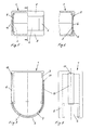
- the radiation detector has a housing 1 which is provided with a window 2 towards the front, in which there is an optic 3 designed as a fixed lens.
- the optics 3 has a detection angle ⁇ 1, which in this case is somewhat less than 180 °.
- the infrared radiation recorded in the area of the detection angle ⁇ 1 is focused on a sensor 4 by the optics 3.
- a frame 5 is glued onto the housing 1, which could also be molded on in the same material.
- the frame 5 with the optics 3 forms a guide channel 7 into which a cover element 6 can be inserted.
- the cover element 6, which is preferably designed as a strip-shaped film, is pushed into a partial area 8 in front of the optics 3, which is covered in an angular range ⁇ 3. If the cover element 6 is opaque to infrared radiation, the sensor 4 in the range of the angle ⁇ 3 no radiation is supplied. However, if the cover element 6 only has a damping effect, the one received by the sensor 4 is reduced Infrared radiation. The actual detection angle with which the infrared detector receives the infrared radiation undiminished is thus reduced to an angle ⁇ 2.
- the detector is provided on both sides with openings 9 which lie in the end region of the optics 3 and which allow the cover element 6 to be inserted. This makes it possible to selectively limit the detection angle ⁇ extending horizontally on one side by a cover element 6 or on both sides by two cover elements 6.
- FIGS. 5 to 8 A second variant for designing a guide channel 7 with the aid of a frame 5 is shown in FIGS. 5 to 8.
- the frame 5 is integrally formed on the housing 1 material.
- the guide channel 7 which can be seen particularly well in FIG. 7
- the frame 5 surrounding it is extended over the front of the housing 1 into the region of its two side walls.
- the part of the guide channel 7 which extends into the region of the side walls can accommodate the cover element 6 over its entire length.
- the detector can therefore in principle be provided with a cover element 6, which, however, is only pushed into the area of the optics when required.
- the cover element 6 is provided at its end away from the window with a handle 11 on which the hand or a tool can engage.
- a web serves as a handle, which extends approximately at a right angle from the plane of the cover element protrudes.
- the handle 11 is narrower than the cover element 6, so that a correspondingly narrow slot 10 is sufficient to ensure the mobility of the web 11 when moving the cover element, but on the other hand to prevent the cover element 6 from falling out.
- the handle 11 can also be arranged in the area of the window or at any other point, provided that only its free mobility is ensured.
- the radiation detector can be adapted even more universally to its respective application by appropriately designing the cover element 6. So it may be desirable that the cover element 6 in the partial area ⁇ 3 of the detection angle for the infrared radiation is completely opaque, or possibly only attenuates it. To achieve a certain attenuation, it may be necessary to work with foils that absorb infrared radiation in very different ways. In addition, it is by no means always in the entire sub-area 8 an equal absorption must be required. In order to meet the possibly very different requirements, a wide range of different cover elements 6 would have to be available, which would result in corresponding storage.
- this object can be achieved relatively simply by storing only one film of relatively low absorption, and then obtaining the cover element 6 by superimposing several films with the desired infrared transmission.
- individual foils 12 can be superimposed congruently, or, as shown in FIG. 4, staggered in relation to one another.
- the strip-shaped foils 12 can have the same length, and can thus be graded as desired. So that the foils 12 do not shift relative to one another, it is possible to glue them onto a transparent carrier 13.
- the carrier can be an infrared-permeable adhesive film or can also be provided with a handle at its end as a custom-made product.
- the individual stages of different infrared transmission can be adapted to the width of the individual zones of the lens. In this way, different sensitivities in the edge area of the optics can also be compensated for.
Landscapes
- Physics & Mathematics (AREA)
- General Physics & Mathematics (AREA)
- Photometry And Measurement Of Optical Pulse Characteristics (AREA)
- Analysing Materials By The Use Of Radiation (AREA)
- Measurement Of Radiation (AREA)
- Treatments Of Macromolecular Shaped Articles (AREA)
- Radiation Pyrometers (AREA)
- Radiation-Therapy Devices (AREA)
- Surgical Instruments (AREA)
- Pharmaceuticals Containing Other Organic And Inorganic Compounds (AREA)
Claims (13)
- Détecteur de rayonnement, en particulier détecteur infrarouge réagissant au rayonnement thermique, destiné à être utilisé comme détecteur de mouvement, détecteur comportant un boîtier pourvu d'une fenêtre qui laisse passer le rayonnement et dont la taille est adaptée à l'angle de champ d'une optique qui est disposée derrière ladite fenêtre et focalise le rayonnement sur un capteur optique, de préférence au moyen d'une lentille de Fresnel, caractérisé par le fait que la fenêtre (2) est pourvue d'un cadre (5) destiné à recevoir et à guider au moins un cache (6) réduisant le rayonnement infrarouge, de préférence un film de matière plastique en forme de bande qui peut être déplacé devant la fenêtre (2) dans un conduit de guidage (7) de manière telle que ledit film couvre une zone partielle (8) variable de l'optique (3).
- Détecteur selon la revendication 1, caractérisé par le fait que le conduit de guidage (7) s'étend au delà de la zone de la fenêtre (2) située sur la face avant du boîtier(1) et se prolonge sur le grand côté voisin du boîtier (1), de préférence de chaque côté.
- Détecteur selon l'une des revendications précédentes, caractérisé par le fait que le conduit de guidage (7) comporte d'un côté au moins une première ouverture (9) permettant l'introduction du cache (6) et que la première ouverture ou une deuxième ouverture (10) permet d'accéder au cache (6) pour l'amener dans la position souhaitée devant une zone partielle (8) de l'optique (3).
- Détecteur selon l'une des revendications précédentes, caractérisé par le fait que le cache (6) agencé sous forme de bande limite par sa première extrémité l'angle de champ (α₂) de l'optique (3) et, peut être saisi par sa deuxième extrémité faisant saillie par une ouverture (9,10) et amené dans sa position variable.
- Détecteur selon l'une des revendications précédentes, caractérisé par le fait qu'un logement est aménagé dans le prolongement du conduit de guidage (7) dans la même direction que celui-ci, logement dans lequel, après réglage, l'extrémité du cache (6) flexible saisie à la main peut être introduite et hors duquel elle peut le cas échéant être dégagée.
- Détecteur selon l'une des revendications précédentes, caractérisé par le fait que l'extrémité du cache (6) en forme de bande qui ne s'étend pas dans la une de la fenêtre (2) est pourvue d'un moyen formant prise (11), de préférence d'une barrette disposée à angle droit qui fait saillie hors du conduit de guidage (7) et qui, lors du déplacement du cache, se déplace dans une fente (10) du conduit (7) qui est ouverte sur l'extérieur et dont la largeur est inférieure à celle du cache (6) en forme de bande.
- Détecteur selon l'une des revendications précédentes, caractérisé par le fait que le cache (6) limite l'angle de champ (α₂) dans un plan horizontal.
- Détecteur selon l'une des revendications précédentes, caractérisé par le fait que le cadre (5) avec le conduit de guidage (7) est aménagé sur le boîtier (1).
- Détecteur selon l'une des revendications précédentes, caractérisé par le fait que le cadre (5) avec le conduit de guidage (7) constitue un élément séparé qui peut être monté sur le boîtier (1) de manière à ne gêner ni la région de la fenêtre (2), ni des éléments de montage prévus sur le boîtier (1) ni des fils d'alimentation extérieurs.
- Détecteur selon l'une des revendications précédentes, caractérisé par le fait que le cadre (5) est pourvu d'éléments de fixation flexibles qui entourent le boîtier (1) grâce auxquels il se monte par accrochage sur le boîtier (1).
- Détecteur selon l'une des revendications précédentes, caractérisé par le fait que le cadre (5) entoure les six côtés d'un boîtier (1) sensiblement parallélépipédique et que deux côtés au moins dudit boîtier restent accessibles par des ouvertures.
- Détecteur selon l'une des revendications précédentes, caractérisé par le fait que le cache (6) en forme de bande est constitué d'un matériau qui ne laisse pas passer ou atténue l'infrarouge.
- Détecteur selon l'une des revendications précédentes, caractérisé par le fait que le conduit de guidage est dimensionné par rapport au cache de manière à permettre le montage l'un sur l'autre de plusieurs films atténuant l'infrarouge, les films superposés coïncidant ou étant décalés selon le cas.
Priority Applications (1)
| Application Number | Priority Date | Filing Date | Title |
|---|---|---|---|
| AT88121211T ATE89092T1 (de) | 1987-12-24 | 1988-12-19 | Strahlungsdetektor. |
Applications Claiming Priority (2)
| Application Number | Priority Date | Filing Date | Title |
|---|---|---|---|
| DE3744182 | 1987-12-24 | ||
| DE3744182A DE3744182C2 (de) | 1987-12-24 | 1987-12-24 | Infrarotdetektor |
Publications (3)
| Publication Number | Publication Date |
|---|---|
| EP0323601A2 EP0323601A2 (fr) | 1989-07-12 |
| EP0323601A3 EP0323601A3 (en) | 1990-05-30 |
| EP0323601B1 true EP0323601B1 (fr) | 1993-05-05 |
Family
ID=6343664
Family Applications (1)
| Application Number | Title | Priority Date | Filing Date |
|---|---|---|---|
| EP88121211A Expired - Lifetime EP0323601B1 (fr) | 1987-12-24 | 1988-12-19 | Détecteur à radiations |
Country Status (6)
| Country | Link |
|---|---|
| US (1) | US4960995A (fr) |
| EP (1) | EP0323601B1 (fr) |
| AT (1) | ATE89092T1 (fr) |
| DE (3) | DE8717763U1 (fr) |
| DK (1) | DK172323B1 (fr) |
| NO (1) | NO175693C (fr) |
Families Citing this family (28)
| Publication number | Priority date | Publication date | Assignee | Title |
|---|---|---|---|---|
| DE3932943A1 (de) * | 1989-10-03 | 1991-04-11 | Asea Brown Boveri | Passiv-infrarot-bewegungsmelder |
| DE4006631C2 (de) * | 1990-03-03 | 1994-11-24 | Berker Geb | Schutzabdeckung für einen passiven Infrarotbewegungsmelder mit der Möglichkeit, einen Überwachungsbereich einzustellen |
| DE9010896U1 (de) * | 1990-07-23 | 1990-10-31 | Albrecht Jung GmbH & Co KG, 58579 Schalksmühle | Passiver Infrarotbewegungsmelder |
| DE4100536A1 (de) * | 1991-01-10 | 1992-07-16 | Hochkoepper Paul Gmbh | Infrarotbewegungsmelder |
| US5239296A (en) * | 1991-10-23 | 1993-08-24 | Black Box Technologies | Method and apparatus for receiving optical signals used to determine vehicle velocity |
| US5302778A (en) * | 1992-08-28 | 1994-04-12 | Eastman Kodak Company | Semiconductor insulation for optical devices |
| US5604483A (en) * | 1995-02-08 | 1997-02-18 | Giangardella; John J. | Portable personal security device |
| DE29503531U1 (de) * | 1995-03-03 | 1995-05-18 | REV Ritter GmbH, 63776 Mömbris | Bewegungsmelder mit Infrarotsensor |
| US5652567A (en) * | 1995-08-22 | 1997-07-29 | C.O.P. Corp. | Adjustable zone security system |
| US5739753A (en) * | 1996-09-19 | 1998-04-14 | Leviton Manufacturing Co., Inc. | Detector system with adjustable field of view |
| DE19639318C1 (de) * | 1996-09-25 | 1997-12-18 | Andreas Toeteberg | Mehrfach-Passiv-Infrarot-(PIR)-Bewegungsmelder |
| US6348686B1 (en) | 1999-07-14 | 2002-02-19 | Hubbell Incorporated | Adapter for positioning a lens |
| US6479823B1 (en) | 1999-08-11 | 2002-11-12 | Hubbell Incorporated | Apparatus and method for lens adjustment |
| ES2224926T3 (es) * | 2000-01-28 | 2005-03-16 | Feller Ag | Detector de movimiento y presencia a infrarrojos con optica conmutable. |
| NL1024282C2 (nl) * | 2003-09-12 | 2005-03-15 | Tno | Inrichting, alsmede werkwijze voor het bepalen van de lichtsterkte van een verkeerslantaarn. |
| US6987267B1 (en) * | 2003-11-07 | 2006-01-17 | Cordelia Lighting, Inc. | Lens blind feature for motion detector |
| EP1605225A1 (fr) * | 2004-06-07 | 2005-12-14 | Honeywell Aerospatiale Inc. | Blindage réactif pour véhicules blindés |
| FR2876824A1 (fr) * | 2004-10-14 | 2006-04-21 | Atral Soc Par Actions Simplifi | Dispositif de detection et/ou d'emission de rayonnements a pastilles-ecrans, en particulier de rayonnements infrarouges |
| US8023818B2 (en) * | 2008-07-24 | 2011-09-20 | Fluke Corporation | Articulating infrared window |
| FR2934377B1 (fr) | 2008-07-28 | 2010-10-29 | Hager Controls | Detecteur de passage a zones de detection pouvant etre predefinies |
| US8891001B2 (en) * | 2012-10-04 | 2014-11-18 | Non Typical, Inc. | Automated camera assembly with infrared detector curtain |
| ITUB20154120A1 (it) * | 2015-10-06 | 2017-04-06 | E Voluzione Di F M Sacerdoti Srl | Sistema di sicurezza e protezione per armadi a rack |
| EP3543978A1 (fr) * | 2015-11-23 | 2019-09-25 | Essence Security International Ltd. | Dispositif de détection de mouvement réglable |
| ES2664135B1 (es) * | 2016-10-18 | 2018-12-20 | Electronic Intelligent Controls, S.L. | Dispositivo detector de movimiento |
| IT201800003637A1 (it) * | 2018-03-15 | 2019-09-15 | Tecnoalarm S R L | Involucro contenitore per dispositivo rivelatore IR |
| US10385561B1 (en) * | 2018-11-15 | 2019-08-20 | Virginia Hall | Automatic purifier switch cover |
| CN112925038B (zh) * | 2021-01-29 | 2022-03-15 | 广东奥莱敏控技术有限公司 | 感应窗口可调节结构及感应器 |
| DE102022114124B4 (de) | 2022-06-03 | 2025-12-31 | Steinel Gmbh | Sensor mit Abdeckvorrichtung und Abdeckvorrichtung für diesen |
Family Cites Families (14)
| Publication number | Priority date | Publication date | Assignee | Title |
|---|---|---|---|---|
| CH596620A5 (fr) * | 1976-06-21 | 1978-03-15 | Cerberus Ag | |
| GB1551541A (en) * | 1977-09-13 | 1979-08-30 | Bloice J A | Infrared intrusion detector system |
| US4192372A (en) * | 1978-08-03 | 1980-03-11 | The Air Preheater Company, Inc. | Adjustable lever for fire detection system |
| US4258255A (en) * | 1979-04-23 | 1981-03-24 | American District Telegraph Company | Infrared intrusion detection system |
| US4447726A (en) * | 1982-04-16 | 1984-05-08 | Cerberus Ag | Passive infrared intrusion detector |
| EP0113468B1 (fr) * | 1983-01-05 | 1990-07-11 | Marcel Dipl.-Ing. ETH Züblin | Dispositif de déflexion des rayons optiques |
| JPS6047977A (ja) * | 1983-08-26 | 1985-03-15 | Matsushita Electric Works Ltd | 赤外線人体検知装置 |
| DE3423494C2 (de) * | 1984-06-26 | 1986-09-04 | Deutsche Forschungs- und Versuchsanstalt für Luft- und Raumfahrt e.V., 5000 Köln | Einrichtung zur Messung der aus dem Halbraum kommenden elektromagnetischen Strahlung |
| US4604524A (en) * | 1984-10-11 | 1986-08-05 | Yaacov Kotlicki | Passive infra-red sensor |
| US4795908A (en) * | 1986-02-25 | 1989-01-03 | Masushita Electric Works, Ltd. | Infrared detector |
| US4769545A (en) * | 1986-11-26 | 1988-09-06 | American Iris Corporation | Motion detector |
| DE3722362A1 (de) * | 1987-07-07 | 1989-01-19 | Insta Elektro Gmbh & Co Kg | Vorrichtung fuer einen infrarot-bewegungsmelder zur variabilitaet seines erfassungswinkels |
| US4799243A (en) * | 1987-09-01 | 1989-01-17 | Otis Elevator Company | Directional people counting arrangement |
| US4841284A (en) * | 1987-10-19 | 1989-06-20 | C & K Systems, Inc. | Infrared intrusion detection system incorporating a fresnel lens and a mirror |
-
1987
- 1987-12-24 DE DE8717763U patent/DE8717763U1/de not_active Expired - Lifetime
- 1987-12-24 DE DE3744182A patent/DE3744182C2/de not_active Expired - Fee Related
-
1988
- 1988-12-19 DE DE8888121211T patent/DE3880813D1/de not_active Expired - Fee Related
- 1988-12-19 AT AT88121211T patent/ATE89092T1/de active
- 1988-12-19 EP EP88121211A patent/EP0323601B1/fr not_active Expired - Lifetime
- 1988-12-19 DK DK705688A patent/DK172323B1/da not_active IP Right Cessation
- 1988-12-23 NO NO885746A patent/NO175693C/no unknown
- 1988-12-27 US US07/290,022 patent/US4960995A/en not_active Expired - Fee Related
Also Published As
| Publication number | Publication date |
|---|---|
| DE8717763U1 (de) | 1990-01-11 |
| US4960995A (en) | 1990-10-02 |
| DE3880813D1 (de) | 1993-06-09 |
| DK705688D0 (da) | 1988-12-19 |
| NO175693C (no) | 1994-11-16 |
| DK705688A (da) | 1989-06-25 |
| NO175693B (no) | 1994-08-08 |
| EP0323601A2 (fr) | 1989-07-12 |
| NO885746L (no) | 1989-06-26 |
| DK172323B1 (da) | 1998-03-16 |
| ATE89092T1 (de) | 1993-05-15 |
| EP0323601A3 (en) | 1990-05-30 |
| NO885746D0 (no) | 1988-12-23 |
| DE3744182A1 (de) | 1989-07-06 |
| DE3744182C2 (de) | 1994-06-30 |
Similar Documents
| Publication | Publication Date | Title |
|---|---|---|
| EP0323601B1 (fr) | Détecteur à radiations | |
| EP0370426B1 (fr) | Détecteur infrarouge d'intrusion | |
| DE69323532T2 (de) | Leser von optischen Informationen | |
| EP0050751B1 (fr) | Arrangement optique pour un détecteur d'intrusion à infrarouge | |
| DE2103909C3 (de) | Überwachungseinrichtung zur Feststellung eines Eindringlings, | |
| DE19628050C2 (de) | Infrarotmeßgerät und Verfahren der Erfassung eines menschlichen Körpers durch dieses | |
| DE3129753A1 (de) | Passive infrarot-raumschutzeinrichtung | |
| DE2904654A1 (de) | Optische anordnung fuer einen passiven infrarot-bewegungsmelder | |
| DE3114112A1 (de) | Einbruchsdetektorsystem | |
| DE60204249T2 (de) | Optischer Detektor | |
| EP0542170B1 (fr) | Détecteur passif de mouvement à infrarouge | |
| DE3119720A1 (de) | Bewegungsmelder zur raumueberwachung | |
| DE3812969A1 (de) | Infrarot-bewegungsmelder | |
| EP0191155A1 (fr) | Détecteur infrarouge d'intrusion | |
| DE3803305C3 (de) | Vorrichtung zum Erfassen der Scharfeinstellung eines Kameraobjektivs | |
| CH667744A5 (de) | Infrarot-eindringdetektor. | |
| CH651941A5 (de) | Optische anordnung fuer einen strahlungsdetektor. | |
| DE3200957C2 (fr) | ||
| EP0050750B1 (fr) | Détecteur d'intrusion à infrarouge | |
| AT514174B1 (de) | Kamerasystem zur Herstellung von Panoramaaufnahmen | |
| DE19625235A1 (de) | Bewegungsmelder zur Detektion von Wärmestrahlung abgebenden, beweglichen Objekten | |
| DE3227118C2 (de) | Fenster | |
| DE3424135A1 (de) | Meldeeinrichtung zur raumueberwachung | |
| DE3500860A1 (de) | Optische anordnung an passiv-infrarot-bewegungsmeldern | |
| EP0262241A1 (fr) | Détecteur d'intrusion à infrarouge |
Legal Events
| Date | Code | Title | Description |
|---|---|---|---|
| PUAI | Public reference made under article 153(3) epc to a published international application that has entered the european phase |
Free format text: ORIGINAL CODE: 0009012 |
|
| AK | Designated contracting states |
Kind code of ref document: A2 Designated state(s): AT BE CH DE FR GB IT LI NL SE |
|
| PUAL | Search report despatched |
Free format text: ORIGINAL CODE: 0009013 |
|
| AK | Designated contracting states |
Kind code of ref document: A3 Designated state(s): AT BE CH DE FR GB IT LI NL SE |
|
| 17P | Request for examination filed |
Effective date: 19900703 |
|
| 17Q | First examination report despatched |
Effective date: 19921005 |
|
| GRAA | (expected) grant |
Free format text: ORIGINAL CODE: 0009210 |
|
| AK | Designated contracting states |
Kind code of ref document: B1 Designated state(s): AT BE CH DE FR GB IT LI NL SE |
|
| REF | Corresponds to: |
Ref document number: 89092 Country of ref document: AT Date of ref document: 19930515 Kind code of ref document: T |
|
| REF | Corresponds to: |
Ref document number: 3880813 Country of ref document: DE Date of ref document: 19930609 |
|
| GBT | Gb: translation of ep patent filed (gb section 77(6)(a)/1977) |
Effective date: 19930514 |
|
| ITF | It: translation for a ep patent filed | ||
| ET | Fr: translation filed | ||
| PLBE | No opposition filed within time limit |
Free format text: ORIGINAL CODE: 0009261 |
|
| STAA | Information on the status of an ep patent application or granted ep patent |
Free format text: STATUS: NO OPPOSITION FILED WITHIN TIME LIMIT |
|
| 26N | No opposition filed | ||
| EAL | Se: european patent in force in sweden |
Ref document number: 88121211.2 |
|
| PGFP | Annual fee paid to national office [announced via postgrant information from national office to epo] |
Ref country code: NL Payment date: 19980923 Year of fee payment: 11 |
|
| PGFP | Annual fee paid to national office [announced via postgrant information from national office to epo] |
Ref country code: FR Payment date: 19980925 Year of fee payment: 11 |
|
| PGFP | Annual fee paid to national office [announced via postgrant information from national office to epo] |
Ref country code: SE Payment date: 19980928 Year of fee payment: 11 Ref country code: GB Payment date: 19980928 Year of fee payment: 11 |
|
| PGFP | Annual fee paid to national office [announced via postgrant information from national office to epo] |
Ref country code: CH Payment date: 19981020 Year of fee payment: 11 |
|
| PGFP | Annual fee paid to national office [announced via postgrant information from national office to epo] |
Ref country code: AT Payment date: 19981023 Year of fee payment: 11 |
|
| PGFP | Annual fee paid to national office [announced via postgrant information from national office to epo] |
Ref country code: BE Payment date: 19981109 Year of fee payment: 11 |
|
| PG25 | Lapsed in a contracting state [announced via postgrant information from national office to epo] |
Ref country code: GB Free format text: LAPSE BECAUSE OF NON-PAYMENT OF DUE FEES Effective date: 19991219 Ref country code: AT Free format text: LAPSE BECAUSE OF NON-PAYMENT OF DUE FEES Effective date: 19991219 |
|
| PG25 | Lapsed in a contracting state [announced via postgrant information from national office to epo] |
Ref country code: SE Free format text: LAPSE BECAUSE OF NON-PAYMENT OF DUE FEES Effective date: 19991220 |
|
| PG25 | Lapsed in a contracting state [announced via postgrant information from national office to epo] |
Ref country code: LI Free format text: LAPSE BECAUSE OF NON-PAYMENT OF DUE FEES Effective date: 19991231 Ref country code: CH Free format text: LAPSE BECAUSE OF NON-PAYMENT OF DUE FEES Effective date: 19991231 Ref country code: BE Free format text: LAPSE BECAUSE OF NON-PAYMENT OF DUE FEES Effective date: 19991231 |
|
| BERE | Be: lapsed |
Owner name: ASEA BROWN BOVERI A.G. Effective date: 19991231 |
|
| PG25 | Lapsed in a contracting state [announced via postgrant information from national office to epo] |
Ref country code: NL Free format text: LAPSE BECAUSE OF NON-PAYMENT OF DUE FEES Effective date: 20000701 |
|
| GBPC | Gb: european patent ceased through non-payment of renewal fee |
Effective date: 19991219 |
|
| EUG | Se: european patent has lapsed |
Ref document number: 88121211.2 |
|
| PG25 | Lapsed in a contracting state [announced via postgrant information from national office to epo] |
Ref country code: FR Free format text: LAPSE BECAUSE OF NON-PAYMENT OF DUE FEES Effective date: 20000831 |
|
| NLV4 | Nl: lapsed or anulled due to non-payment of the annual fee |
Effective date: 20000701 |
|
| REG | Reference to a national code |
Ref country code: FR Ref legal event code: ST |
|
| PGFP | Annual fee paid to national office [announced via postgrant information from national office to epo] |
Ref country code: DE Payment date: 20011026 Year of fee payment: 14 |
|
| PG25 | Lapsed in a contracting state [announced via postgrant information from national office to epo] |
Ref country code: DE Free format text: LAPSE BECAUSE OF NON-PAYMENT OF DUE FEES Effective date: 20030701 |
|
| PG25 | Lapsed in a contracting state [announced via postgrant information from national office to epo] |
Ref country code: IT Free format text: LAPSE BECAUSE OF NON-PAYMENT OF DUE FEES;WARNING: LAPSES OF ITALIAN PATENTS WITH EFFECTIVE DATE BEFORE 2007 MAY HAVE OCCURRED AT ANY TIME BEFORE 2007. THE CORRECT EFFECTIVE DATE MAY BE DIFFERENT FROM THE ONE RECORDED. Effective date: 20051219 |