EP0323638A1 - Injecteur de carburant - Google Patents
Injecteur de carburant Download PDFInfo
- Publication number
- EP0323638A1 EP0323638A1 EP88121833A EP88121833A EP0323638A1 EP 0323638 A1 EP0323638 A1 EP 0323638A1 EP 88121833 A EP88121833 A EP 88121833A EP 88121833 A EP88121833 A EP 88121833A EP 0323638 A1 EP0323638 A1 EP 0323638A1
- Authority
- EP
- European Patent Office
- Prior art keywords
- carrier
- ceramic plates
- plate
- ceramic
- plates
- Prior art date
- Legal status (The legal status is an assumption and is not a legal conclusion. Google has not performed a legal analysis and makes no representation as to the accuracy of the status listed.)
- Withdrawn
Links
- 239000000446 fuel Substances 0.000 title claims abstract description 17
- 239000000919 ceramic Substances 0.000 claims abstract description 48
- 239000004020 conductor Substances 0.000 claims abstract description 17
- 239000011888 foil Substances 0.000 claims abstract description 16
- 238000002347 injection Methods 0.000 claims abstract description 15
- 239000007924 injection Substances 0.000 claims abstract description 15
- 239000002184 metal Substances 0.000 claims description 6
- 230000005284 excitation Effects 0.000 claims description 4
- 238000005452 bending Methods 0.000 abstract description 9
- 230000006835 compression Effects 0.000 description 3
- 238000007906 compression Methods 0.000 description 3
- 239000002131 composite material Substances 0.000 description 1
- 238000007796 conventional method Methods 0.000 description 1
- 238000006073 displacement reaction Methods 0.000 description 1
- 230000005281 excited state Effects 0.000 description 1
Images



Classifications
-
- F—MECHANICAL ENGINEERING; LIGHTING; HEATING; WEAPONS; BLASTING
- F02—COMBUSTION ENGINES; HOT-GAS OR COMBUSTION-PRODUCT ENGINE PLANTS
- F02M—SUPPLYING COMBUSTION ENGINES IN GENERAL WITH COMBUSTIBLE MIXTURES OR CONSTITUENTS THEREOF
- F02M51/00—Fuel-injection apparatus characterised by being operated electrically
- F02M51/06—Injectors peculiar thereto with means directly operating the valve needle
- F02M51/0603—Injectors peculiar thereto with means directly operating the valve needle using piezoelectric or magnetostrictive operating means
-
- F—MECHANICAL ENGINEERING; LIGHTING; HEATING; WEAPONS; BLASTING
- F02—COMBUSTION ENGINES; HOT-GAS OR COMBUSTION-PRODUCT ENGINE PLANTS
- F02M—SUPPLYING COMBUSTION ENGINES IN GENERAL WITH COMBUSTIBLE MIXTURES OR CONSTITUENTS THEREOF
- F02M51/00—Fuel-injection apparatus characterised by being operated electrically
- F02M51/005—Arrangement of electrical wires and connections, e.g. wire harness, sockets, plugs; Arrangement of electronic control circuits in or on fuel injection apparatus
-
- H—ELECTRICITY
- H10—SEMICONDUCTOR DEVICES; ELECTRIC SOLID-STATE DEVICES NOT OTHERWISE PROVIDED FOR
- H10N—ELECTRIC SOLID-STATE DEVICES NOT OTHERWISE PROVIDED FOR
- H10N30/00—Piezoelectric or electrostrictive devices
- H10N30/20—Piezoelectric or electrostrictive devices with electrical input and mechanical output, e.g. functioning as actuators or vibrators
- H10N30/204—Piezoelectric or electrostrictive devices with electrical input and mechanical output, e.g. functioning as actuators or vibrators using bending displacement, e.g. unimorph, bimorph or multimorph cantilever or membrane benders
- H10N30/2047—Membrane type
Definitions
- the invention relates to a fuel injection valve with a piezoceramic valve body comprising ceramic plates stacked on top of one another with voltage supplies to each ceramic plate, each ceramic plate being seated on a carrier plate, a conductor foil being arranged between adjacent carrier ceramic plates and connecting lugs of the conductor foils being connected to different contacts.
- Such a fuel injection valve is known from DE-OS 35 32 660.
- Bending oscillators with the same polarity and thus the same travel range are stacked on top of each other in order to increase the positioning force. Since the individual bending vibrators deform in the same way when excited, the bending vibrators of a package lie essentially flush against one another during the deformation, so that no difficulties arise.
- DE-OS 24 02 085 shows an arrangement of longitudinal transducers.
- the adjustment paths of the individual longitudinal transducers add up, so that an increase in displacement can be achieved by arranging several longitudinal transducers. Since the longitudinal transducers abut each other essentially bluntly, there are no difficulties with the arrangement here either.
- the object of the invention is to increase the travel of a piezoceramic valve when using bending transducers.
- the invention differs from the prior art in that in each case the carrier ceramic plates of a pair are excited are deformed opposite to each other, so that this results in an enlargement of the path.
- the carrier ceramic plates of each pair are convexly curved with respect to one another when an excitation voltage is applied and are supported directly against one another in the central region.
- a metal ring is arranged between the carrier ceramic plates of each pair, on which the carrier ceramic plates are supported on the one hand and on the other hand has a connection contact for the carrier ceramic plate pair. In contrast to a foil, the metal ring is not worn even after long use.
- a variable support for transferring the adjustment is achieved in that the edge regions of the carrier ceramic plates are each supported on a plate which transmits the valve movement to the closure body.
- the carrier ceramic plates of each pair are concave to one another when an excitation voltage is applied and are supported against one another at the edge in each case.
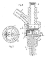
- the fuel injection valve comprises a valve housing 1 with a cover 2 and an injection nozzle 3. Inside the injection nozzle 3 there is an injection channel 4, which is closed off by a closure body 3 seated on a valve stem 6. A fuel supply channel 7 and a filter body 8 are located inside the cover. There is also a plug connection 9 with two contact pins 10, 11 provided.
- a piezoceramic plate pack 12 Inside the valve housing 1 there is a piezoceramic plate pack 12. The same is made up of several plate-shaped bending oscillators.
- Each bending oscillator comprises a metallic carrier plate 13, which carries a ceramic plate 14 in each case.
- the ceramic plate 14 is firmly connected to the respective carrier plate 13 according to the conventional technique.
- the carrier plates 13 each abut one another.
- a conductor foil 16 is located between the carrier plates 13.
- Each ceramic plate 14 rests on a conductor foil 16 which is supported on a plate 17 or 18.
- the plate 17 lies on the one hand on a collar 19 of the valve stem 6 and on the other hand on a collar 20 of the valve housing 1. In the area of the federal government 20 there are passage channels 21 for the fuel.
- a spring washer 22 is supported on the plate 18 and is held in a groove 23 of the valve stem 6. This spring washer 22 holds the plate pack 12 together, so that sufficient electrical contact between the conductor foils 6 and the carrier plates 13 or ceramic plates 14 is ensured.
- connection lugs 26 The conductor foils 16 of a voltage polarity, which have contact with the ceramic plates, are extended in connection lugs 26.
- the conductor foil 16 of the other voltage polarity which bears on the carrier plates 13, is connected to a connecting tab 27 and placed on the contact pin 11 of the corresponding polarity. This ensures a secure conductive connection.
- the contact pin 11 is fastened and fixed in the support plate 24.
- the connecting lugs 26 and 27 are offset from one another in the circumferential direction.
- a metal ring can also be arranged between the ceramic plates.
- the metal ring only needs to support the carrier ceramic plates in the middle area, since the carrier ceramic plates bulge away from one another when excited. It is then Sufficient contacting is always guaranteed.
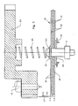
- Fig. 3 shows the basic state of the valve in which the ceramic plates are not excited.
- the ceramic plates 14 are flat, so that the valve stem 6 is stretched by the compression spring 25. As a result, the fuel injector is blocked.
- Fig. 4 shows the energized state of the valve. Due to the applied voltage, the ceramic plates are each bent with a convex curvature and are supported against each other in the central area. The metal plate 17 is supported on the shoulder 20. The valve stem 6 is raised so that the fuel injection valve is open. Each ceramic plate provides the same amount of deflection and thus the amount of travel for the opening movement of the valve stem. As a result, with two ceramic plates, a double opening path is obtained compared to the path caused by a ceramic plate.
- FIG. 5 and 6 show a further embodiment of the invention.
- the ceramic plates 14 sit on opposite sides of a composite film made of an insulating film 15 with two conductor films 16.
- the two conductor films 16 lead to connecting lugs 26 which are connected to the connecting web 11.
- These conductor foils are led to connecting lugs 27.
- a ceramic plate 14 is supported on the spring washer 22.
- the other ceramic plate 14 is supported on an insulating plate 28, which rests on a shoulder 20 of the valve housing.
- FIG. 5 shows the basic state of the fuel injection valve
- FIG. 6 shows the excited state in which the valve is open.
- the ceramic plates are concave.
Landscapes
- Engineering & Computer Science (AREA)
- Chemical & Material Sciences (AREA)
- Combustion & Propulsion (AREA)
- Mechanical Engineering (AREA)
- General Engineering & Computer Science (AREA)
- Fuel-Injection Apparatus (AREA)
Applications Claiming Priority (2)
| Application Number | Priority Date | Filing Date | Title |
|---|---|---|---|
| DE3800203 | 1988-01-07 | ||
| DE3800203A DE3800203C2 (de) | 1988-01-07 | 1988-01-07 | Kraftstoffeinspritzventil |
Publications (1)
| Publication Number | Publication Date |
|---|---|
| EP0323638A1 true EP0323638A1 (fr) | 1989-07-12 |
Family
ID=6344888
Family Applications (1)
| Application Number | Title | Priority Date | Filing Date |
|---|---|---|---|
| EP88121833A Withdrawn EP0323638A1 (fr) | 1988-01-07 | 1988-12-29 | Injecteur de carburant |
Country Status (4)
| Country | Link |
|---|---|
| US (1) | US4927084A (fr) |
| EP (1) | EP0323638A1 (fr) |
| JP (1) | JP2633941B2 (fr) |
| DE (1) | DE3800203C2 (fr) |
Cited By (1)
| Publication number | Priority date | Publication date | Assignee | Title |
|---|---|---|---|---|
| CN109604107A (zh) * | 2018-10-15 | 2019-04-12 | 北京派和科技股份有限公司 | 对称性结构布局的压电喷射阀 |
Families Citing this family (28)
| Publication number | Priority date | Publication date | Assignee | Title |
|---|---|---|---|---|
| US5203537A (en) * | 1992-03-09 | 1993-04-20 | Teledyne Industries, Inc. | Piezoceramic valve actuator sandwich assembly and valve incorporating such an assembly |
| US5471721A (en) * | 1993-02-23 | 1995-12-05 | Research Corporation Technologies, Inc. | Method for making monolithic prestressed ceramic devices |
| DE19644161C2 (de) * | 1995-11-07 | 1998-11-12 | Daimler Benz Aerospace Ag | Piezoelektrischer Aktuator |
| FR2757238B1 (fr) * | 1996-12-12 | 1999-01-08 | Alsthom Cge Alcatel | Agencement de fixation amortisseur pour dispositif a proteger d'au moins certaines vibrations |
| DE19717459C2 (de) * | 1997-04-25 | 1999-03-18 | Bosch Gmbh Robert | Vorrichtung zum dosierten Einspritzen von Kraftstoff in einen Verbrennungsmotor |
| DE19802302A1 (de) | 1998-01-22 | 1999-07-29 | Bosch Gmbh Robert | Piezoelektrischer Aktor |
| US6291930B1 (en) * | 1998-08-13 | 2001-09-18 | Oceaneering International, Inc. | Low voltage piezoelectric bender elements and unit cells |
| DE19858758C1 (de) * | 1998-12-18 | 2000-09-07 | Siemens Ag | Vorrichtung und Verfahren zur Hubübertragung |
| DE19932764A1 (de) | 1999-07-14 | 2001-01-18 | Bosch Gmbh Robert | Brennstoffeinspritzventil |
| DE19943253A1 (de) | 1999-09-10 | 2001-03-15 | Bosch Gmbh Robert | Brennstoffeinspritzventil |
| ATE303658T1 (de) * | 2001-06-27 | 2005-09-15 | Siemens Ag | Piezoelektrischer biegewandler |
| US6792921B2 (en) | 2001-12-17 | 2004-09-21 | Caterpillar Inc | Electronically-controlled fuel injector |
| US6880769B2 (en) * | 2001-12-17 | 2005-04-19 | Caterpillar Inc | Electronically-controlled fuel injector |
| US20030226987A1 (en) * | 2002-06-06 | 2003-12-11 | Gallmeyer Christopher F. | Method and apparatus for seat detection and soft seating in a piezoelectric device actuated valve system |
| US6739575B2 (en) | 2002-06-06 | 2004-05-25 | Caterpillar Inc | Piezoelectric valve system |
| US20040003786A1 (en) * | 2002-06-18 | 2004-01-08 | Gatecliff George W. | Piezoelectric valve actuation |
| US6811093B2 (en) * | 2002-10-17 | 2004-11-02 | Tecumseh Products Company | Piezoelectric actuated fuel injectors |
| US7077379B1 (en) | 2004-05-07 | 2006-07-18 | Brunswick Corporation | Fuel injector using two piezoelectric devices |
| US20050258715A1 (en) * | 2004-05-19 | 2005-11-24 | Schlabach Roderic A | Piezoelectric actuator having minimal displacement drift with temperature and high durability |
| DE102004041170A1 (de) * | 2004-08-25 | 2006-03-09 | Siemens Ag | Kraftstoffinjektor für eine Brennkraftmaschine sowie Verfahren zur Montage eines derartigen Kraftstoffinjektors |
| DE102004056667A1 (de) * | 2004-11-24 | 2006-06-01 | Robert Bosch Gmbh | Elektrische Überbrückung in Kraftstoffinjektoren |
| US7322803B2 (en) * | 2004-12-30 | 2008-01-29 | Adaptivenergy, Llc. | Pumps with diaphragms bonded as bellows |
| US7267043B2 (en) | 2004-12-30 | 2007-09-11 | Adaptivenergy, Llc | Actuators with diaphragm and methods of operating same |
| US20060232162A1 (en) * | 2005-04-13 | 2006-10-19 | Par Technologies, Llc | Electrically driven mechanical actuators and methods of operating same |
| WO2006113344A2 (fr) * | 2005-04-13 | 2006-10-26 | Par Technologies, Llc | Actionneurs a diaphragmes relies |
| US20070075286A1 (en) * | 2005-10-04 | 2007-04-05 | Par Technologies, Llc | Piezoelectric valves drive |
| US20070129681A1 (en) * | 2005-11-01 | 2007-06-07 | Par Technologies, Llc | Piezoelectric actuation of piston within dispensing chamber |
| US7345407B2 (en) * | 2005-11-18 | 2008-03-18 | Adaptivenergy, Llc. | Human powered piezoelectric power generating device |
Citations (2)
| Publication number | Priority date | Publication date | Assignee | Title |
|---|---|---|---|---|
| DE2848812A1 (de) * | 1978-11-10 | 1980-05-22 | Daimler Benz Ag | Stellglied aus piezoelektrischen elementen |
| DE3532660A1 (de) * | 1985-09-13 | 1987-03-26 | Atlas Fahrzeugtechnik Gmbh | Kraftstoffeinspritzventil |
Family Cites Families (9)
| Publication number | Priority date | Publication date | Assignee | Title |
|---|---|---|---|---|
| US3093760A (en) * | 1960-06-15 | 1963-06-11 | Bosch Arma Corp | Composite piezoelectric element |
| US3360664A (en) * | 1964-10-30 | 1967-12-26 | Gen Dynamics Corp | Electromechanical apparatus |
| US4096993A (en) * | 1977-01-21 | 1978-06-27 | Emerson Electric Co. | Compensated control valve |
| US4140936A (en) * | 1977-09-01 | 1979-02-20 | The United States Of America As Represented By The Secretary Of The Navy | Square and rectangular electroacoustic bender bar transducer |
| US4268006A (en) * | 1978-06-02 | 1981-05-19 | Emerson Electric Co. | Modulating diaphragm valve |
| US4601539A (en) * | 1983-05-07 | 1986-07-22 | Canon Kabushiki Kaisha | Lens moving device using piezoelectric material |
| DE3501077A1 (de) * | 1985-01-15 | 1986-07-17 | Kernforschungszentrum Karlsruhe Gmbh, 7500 Karlsruhe | Pulsventil |
| US5152271A (en) * | 1985-07-15 | 1992-10-06 | Osamu Matsumura | Fuel injection apparatus |
| JPS62121860A (ja) * | 1985-11-19 | 1987-06-03 | Osamu Matsumura | 燃料噴射装置 |
-
1988
- 1988-01-07 DE DE3800203A patent/DE3800203C2/de not_active Expired - Fee Related
- 1988-12-28 JP JP63329558A patent/JP2633941B2/ja not_active Expired - Lifetime
- 1988-12-28 US US07/291,946 patent/US4927084A/en not_active Expired - Lifetime
- 1988-12-29 EP EP88121833A patent/EP0323638A1/fr not_active Withdrawn
Patent Citations (2)
| Publication number | Priority date | Publication date | Assignee | Title |
|---|---|---|---|---|
| DE2848812A1 (de) * | 1978-11-10 | 1980-05-22 | Daimler Benz Ag | Stellglied aus piezoelektrischen elementen |
| DE3532660A1 (de) * | 1985-09-13 | 1987-03-26 | Atlas Fahrzeugtechnik Gmbh | Kraftstoffeinspritzventil |
Non-Patent Citations (1)
| Title |
|---|
| NACHRICHTENTECHNIK ELEKTRONIK, Jrg. 27, Nr. 9, 1977, Seiten 381-383, Berlin, DE; P. KUNATH et al.: "Einsatz piezoelektrischer Bauelemente in elektromechanischen Stellgliedern" * |
Cited By (1)
| Publication number | Priority date | Publication date | Assignee | Title |
|---|---|---|---|---|
| CN109604107A (zh) * | 2018-10-15 | 2019-04-12 | 北京派和科技股份有限公司 | 对称性结构布局的压电喷射阀 |
Also Published As
| Publication number | Publication date |
|---|---|
| DE3800203C2 (de) | 1997-08-14 |
| US4927084A (en) | 1990-05-22 |
| JP2633941B2 (ja) | 1997-07-23 |
| JPH01310164A (ja) | 1989-12-14 |
| DE3800203A1 (de) | 1989-07-20 |
Similar Documents
| Publication | Publication Date | Title |
|---|---|---|
| DE3800203C2 (de) | Kraftstoffeinspritzventil | |
| EP0400482B1 (fr) | Microvanne | |
| EP0879373B1 (fr) | Actionneur piezoelectrique | |
| EP0517698B1 (fr) | Pompe microminiaturisee | |
| DE10026005B4 (de) | Piezoaktor | |
| EP0118715B1 (fr) | Relais électromagnétique polarisé | |
| DE102017115883A1 (de) | Leistungselektronisches Submodul mit Gleich- und Wechselspannungsanschlusselementen und Anordnung hiermit | |
| WO1998047187A1 (fr) | Actionneur piezoelectrique a nouveau mode de contact et son procede de fabrication | |
| EP0310605A1 (fr) | Pompe de fluide a actionnement piezoelectrique | |
| DE4034539C2 (fr) | ||
| DE2828435A1 (de) | Druckknopfschalter | |
| DE1540518B1 (de) | Drehschalter | |
| EP1419333A1 (fr) | Soupape hydraulique a commande piezo-electrique | |
| DE4410153C1 (de) | Piezoelektrisch betätigtes Fluidventil | |
| DE102014114212A1 (de) | Membranventil | |
| DE102016114566A1 (de) | Folienwandler und Aktorstreifen für einen Folienwandler | |
| DE3532660C2 (fr) | ||
| EP0191011A1 (fr) | Convertisseur de signaux électropneumatiques | |
| DE3150210C2 (de) | Elektrischer Schnappschalter | |
| DE19946837A1 (de) | Piezoaktor | |
| DE4108416C2 (de) | Kraftstoff-Einspritzdüse für Brennkraftmaschinen | |
| EP2396535B1 (fr) | Actionneur piezoelectrique, procede de production de l'actionneur et injecteur | |
| WO2024231085A1 (fr) | Transducteur doté d'un capteur de tension flexible | |
| DE19928180B4 (de) | Piezoaktor | |
| DE2303465B2 (de) | Kraft- oder Druck-Meßwandler |
Legal Events
| Date | Code | Title | Description |
|---|---|---|---|
| PUAI | Public reference made under article 153(3) epc to a published international application that has entered the european phase |
Free format text: ORIGINAL CODE: 0009012 |
|
| AK | Designated contracting states |
Kind code of ref document: A1 Designated state(s): DE FR GB IT |
|
| 17P | Request for examination filed |
Effective date: 19900112 |
|
| 17Q | First examination report despatched |
Effective date: 19900507 |
|
| STAA | Information on the status of an ep patent application or granted ep patent |
Free format text: STATUS: THE APPLICATION IS DEEMED TO BE WITHDRAWN |
|
| 18D | Application deemed to be withdrawn |
Effective date: 19901120 |