EP0323646A2 - Procédé de séparation d'un composant ayant une pression de vapeur élevée et/ou une substance particulière d'un composant ayant une pression de vapeur basse - Google Patents
Procédé de séparation d'un composant ayant une pression de vapeur élevée et/ou une substance particulière d'un composant ayant une pression de vapeur basse Download PDFInfo
- Publication number
- EP0323646A2 EP0323646A2 EP88121869A EP88121869A EP0323646A2 EP 0323646 A2 EP0323646 A2 EP 0323646A2 EP 88121869 A EP88121869 A EP 88121869A EP 88121869 A EP88121869 A EP 88121869A EP 0323646 A2 EP0323646 A2 EP 0323646A2
- Authority
- EP
- European Patent Office
- Prior art keywords
- stripping
- fluid mixture
- substance
- stripping substance
- venturi
- Prior art date
- Legal status (The legal status is an assumption and is not a legal conclusion. Google has not performed a legal analysis and makes no representation as to the accuracy of the status listed.)
- Granted
Links
- 239000013618 particulate matter Substances 0.000 title claims abstract description 21
- 238000000034 method Methods 0.000 title claims description 68
- 239000000203 mixture Substances 0.000 claims abstract description 192
- 239000000126 substance Substances 0.000 claims abstract description 147
- 239000012530 fluid Substances 0.000 claims abstract description 78
- 238000011144 upstream manufacturing Methods 0.000 claims description 26
- 238000000926 separation method Methods 0.000 claims description 20
- 230000006835 compression Effects 0.000 claims description 16
- 238000007906 compression Methods 0.000 claims description 16
- 238000002347 injection Methods 0.000 claims description 16
- 239000007924 injection Substances 0.000 claims description 16
- 239000006185 dispersion Substances 0.000 claims description 10
- 239000000243 solution Substances 0.000 claims description 10
- 229910052751 metal Inorganic materials 0.000 claims description 9
- 239000002184 metal Substances 0.000 claims description 9
- 239000000725 suspension Substances 0.000 claims description 4
- 239000007864 aqueous solution Substances 0.000 claims description 2
- 229910001092 metal group alloy Inorganic materials 0.000 claims 2
- IJGRMHOSHXDMSA-UHFFFAOYSA-N Atomic nitrogen Chemical compound N#N IJGRMHOSHXDMSA-UHFFFAOYSA-N 0.000 description 176
- 239000001301 oxygen Substances 0.000 description 105
- 229910052760 oxygen Inorganic materials 0.000 description 105
- QVGXLLKOCUKJST-UHFFFAOYSA-N atomic oxygen Chemical compound [O] QVGXLLKOCUKJST-UHFFFAOYSA-N 0.000 description 104
- 239000007789 gas Substances 0.000 description 92
- 229910052757 nitrogen Inorganic materials 0.000 description 90
- 239000007788 liquid Substances 0.000 description 77
- XLYOFNOQVPJJNP-UHFFFAOYSA-N water Substances O XLYOFNOQVPJJNP-UHFFFAOYSA-N 0.000 description 57
- 230000009467 reduction Effects 0.000 description 43
- 238000012546 transfer Methods 0.000 description 28
- 238000005086 pumping Methods 0.000 description 18
- 239000003549 soybean oil Substances 0.000 description 17
- 235000012424 soybean oil Nutrition 0.000 description 17
- 230000002829 reductive effect Effects 0.000 description 13
- 230000008569 process Effects 0.000 description 12
- UFHFLCQGNIYNRP-UHFFFAOYSA-N Hydrogen Chemical compound [H][H] UFHFLCQGNIYNRP-UHFFFAOYSA-N 0.000 description 10
- 229910052782 aluminium Inorganic materials 0.000 description 10
- XAGFODPZIPBFFR-UHFFFAOYSA-N aluminium Chemical compound [Al] XAGFODPZIPBFFR-UHFFFAOYSA-N 0.000 description 10
- 239000002285 corn oil Substances 0.000 description 10
- 239000001257 hydrogen Substances 0.000 description 10
- 229910052739 hydrogen Inorganic materials 0.000 description 10
- 238000002156 mixing Methods 0.000 description 10
- 239000013535 sea water Substances 0.000 description 10
- 235000005687 corn oil Nutrition 0.000 description 9
- 230000035939 shock Effects 0.000 description 9
- 229910001873 dinitrogen Inorganic materials 0.000 description 8
- 125000001495 ethyl group Chemical group [H]C([H])([H])C([H])([H])* 0.000 description 7
- 230000000670 limiting effect Effects 0.000 description 7
- 230000006872 improvement Effects 0.000 description 6
- 230000007423 decrease Effects 0.000 description 5
- 238000011068 loading method Methods 0.000 description 5
- 230000036961 partial effect Effects 0.000 description 5
- 238000012545 processing Methods 0.000 description 5
- XKRFYHLGVUSROY-UHFFFAOYSA-N Argon Chemical compound [Ar] XKRFYHLGVUSROY-UHFFFAOYSA-N 0.000 description 4
- 230000008901 benefit Effects 0.000 description 4
- 238000009792 diffusion process Methods 0.000 description 4
- 239000012071 phase Substances 0.000 description 4
- 238000013459 approach Methods 0.000 description 3
- 230000015572 biosynthetic process Effects 0.000 description 3
- 230000003247 decreasing effect Effects 0.000 description 3
- 238000004519 manufacturing process Methods 0.000 description 3
- 239000000463 material Substances 0.000 description 3
- 239000003921 oil Substances 0.000 description 3
- 235000019198 oils Nutrition 0.000 description 3
- 150000002926 oxygen Chemical class 0.000 description 3
- 229920006395 saturated elastomer Polymers 0.000 description 3
- 238000003860 storage Methods 0.000 description 3
- CURLTUGMZLYLDI-UHFFFAOYSA-N Carbon dioxide Chemical compound O=C=O CURLTUGMZLYLDI-UHFFFAOYSA-N 0.000 description 2
- 229910052786 argon Inorganic materials 0.000 description 2
- 238000004364 calculation method Methods 0.000 description 2
- 238000007872 degassing Methods 0.000 description 2
- 238000010586 diagram Methods 0.000 description 2
- 230000000694 effects Effects 0.000 description 2
- 239000011261 inert gas Substances 0.000 description 2
- 238000009434 installation Methods 0.000 description 2
- 238000011835 investigation Methods 0.000 description 2
- 239000007791 liquid phase Substances 0.000 description 2
- 238000002844 melting Methods 0.000 description 2
- 230000008018 melting Effects 0.000 description 2
- QPJVMBTYPHYUOC-UHFFFAOYSA-N methyl benzoate Chemical compound COC(=O)C1=CC=CC=C1 QPJVMBTYPHYUOC-UHFFFAOYSA-N 0.000 description 2
- 238000012986 modification Methods 0.000 description 2
- 230000004048 modification Effects 0.000 description 2
- TWNQGVIAIRXVLR-UHFFFAOYSA-N oxo(oxoalumanyloxy)alumane Chemical compound O=[Al]O[Al]=O TWNQGVIAIRXVLR-UHFFFAOYSA-N 0.000 description 2
- 238000005191 phase separation Methods 0.000 description 2
- 239000007787 solid Substances 0.000 description 2
- 230000003068 static effect Effects 0.000 description 2
- VHUUQVKOLVNVRT-UHFFFAOYSA-N Ammonium hydroxide Chemical compound [NH4+].[OH-] VHUUQVKOLVNVRT-UHFFFAOYSA-N 0.000 description 1
- OKTJSMMVPCPJKN-UHFFFAOYSA-N Carbon Chemical compound [C] OKTJSMMVPCPJKN-UHFFFAOYSA-N 0.000 description 1
- 239000004215 Carbon black (E152) Substances 0.000 description 1
- ZAMOUSCENKQFHK-UHFFFAOYSA-N Chlorine atom Chemical compound [Cl] ZAMOUSCENKQFHK-UHFFFAOYSA-N 0.000 description 1
- 241000196324 Embryophyta Species 0.000 description 1
- NHWNVPNZGGXQQV-UHFFFAOYSA-J [Si+4].[O-]N=O.[O-]N=O.[O-]N=O.[O-]N=O Chemical compound [Si+4].[O-]N=O.[O-]N=O.[O-]N=O.[O-]N=O NHWNVPNZGGXQQV-UHFFFAOYSA-J 0.000 description 1
- 230000001133 acceleration Effects 0.000 description 1
- 238000005273 aeration Methods 0.000 description 1
- 238000005276 aerator Methods 0.000 description 1
- 230000004075 alteration Effects 0.000 description 1
- 238000004458 analytical method Methods 0.000 description 1
- 238000010923 batch production Methods 0.000 description 1
- 235000013361 beverage Nutrition 0.000 description 1
- 238000009835 boiling Methods 0.000 description 1
- 230000005587 bubbling Effects 0.000 description 1
- 229910002092 carbon dioxide Inorganic materials 0.000 description 1
- 239000001569 carbon dioxide Substances 0.000 description 1
- 235000014171 carbonated beverage Nutrition 0.000 description 1
- 238000005266 casting Methods 0.000 description 1
- 238000001311 chemical methods and process Methods 0.000 description 1
- 238000006243 chemical reaction Methods 0.000 description 1
- 239000000460 chlorine Substances 0.000 description 1
- 229910052801 chlorine Inorganic materials 0.000 description 1
- 238000010276 construction Methods 0.000 description 1
- 239000000356 contaminant Substances 0.000 description 1
- 238000001816 cooling Methods 0.000 description 1
- 239000000498 cooling water Substances 0.000 description 1
- 230000007797 corrosion Effects 0.000 description 1
- 238000005260 corrosion Methods 0.000 description 1
- 238000006392 deoxygenation reaction Methods 0.000 description 1
- 230000003467 diminishing effect Effects 0.000 description 1
- 238000009826 distribution Methods 0.000 description 1
- 238000005516 engineering process Methods 0.000 description 1
- 150000002194 fatty esters Chemical class 0.000 description 1
- 239000000446 fuel Substances 0.000 description 1
- 239000002828 fuel tank Substances 0.000 description 1
- 229910002804 graphite Inorganic materials 0.000 description 1
- 239000010439 graphite Substances 0.000 description 1
- 230000005484 gravity Effects 0.000 description 1
- 229930195733 hydrocarbon Natural products 0.000 description 1
- 150000002430 hydrocarbons Chemical class 0.000 description 1
- 239000012535 impurity Substances 0.000 description 1
- 239000008235 industrial water Substances 0.000 description 1
- 238000005259 measurement Methods 0.000 description 1
- 238000010297 mechanical methods and process Methods 0.000 description 1
- 150000002739 metals Chemical class 0.000 description 1
- 238000010327 methods by industry Methods 0.000 description 1
- 229940095102 methyl benzoate Drugs 0.000 description 1
- QJGQUHMNIGDVPM-UHFFFAOYSA-N nitrogen group Chemical group [N] QJGQUHMNIGDVPM-UHFFFAOYSA-N 0.000 description 1
- 239000003129 oil well Substances 0.000 description 1
- 230000003647 oxidation Effects 0.000 description 1
- 238000007254 oxidation reaction Methods 0.000 description 1
- -1 oxygen saturated nitrogen Chemical class 0.000 description 1
- 238000006213 oxygenation reaction Methods 0.000 description 1
- 238000004391 petroleum recovery Methods 0.000 description 1
- 239000011541 reaction mixture Substances 0.000 description 1
- 238000011084 recovery Methods 0.000 description 1
- 238000004064 recycling Methods 0.000 description 1
- 239000011819 refractory material Substances 0.000 description 1
- 238000011160 research Methods 0.000 description 1
- 238000005070 sampling Methods 0.000 description 1
- HBMJWWWQQXIZIP-UHFFFAOYSA-N silicon carbide Chemical compound [Si+]#[C-] HBMJWWWQQXIZIP-UHFFFAOYSA-N 0.000 description 1
- 229910010271 silicon carbide Inorganic materials 0.000 description 1
- 239000002002 slurry Substances 0.000 description 1
- 238000006467 substitution reaction Methods 0.000 description 1
- 238000009827 uniform distribution Methods 0.000 description 1
Images






Classifications
-
- B—PERFORMING OPERATIONS; TRANSPORTING
- B01—PHYSICAL OR CHEMICAL PROCESSES OR APPARATUS IN GENERAL
- B01D—SEPARATION
- B01D19/00—Degasification of liquids
- B01D19/02—Foam dispersion or prevention
- B01D19/04—Foam dispersion or prevention by addition of chemical substances
-
- B—PERFORMING OPERATIONS; TRANSPORTING
- B01—PHYSICAL OR CHEMICAL PROCESSES OR APPARATUS IN GENERAL
- B01F—MIXING, e.g. DISSOLVING, EMULSIFYING OR DISPERSING
- B01F25/00—Flow mixers; Mixers for falling materials, e.g. solid particles
- B01F25/30—Injector mixers
- B01F25/31—Injector mixers in conduits or tubes through which the main component flows
- B01F25/313—Injector mixers in conduits or tubes through which the main component flows wherein additional components are introduced in the centre of the conduit
-
- B—PERFORMING OPERATIONS; TRANSPORTING
- B01—PHYSICAL OR CHEMICAL PROCESSES OR APPARATUS IN GENERAL
- B01D—SEPARATION
- B01D19/00—Degasification of liquids
- B01D19/0005—Degasification of liquids with one or more auxiliary substances
-
- B—PERFORMING OPERATIONS; TRANSPORTING
- B01—PHYSICAL OR CHEMICAL PROCESSES OR APPARATUS IN GENERAL
- B01J—CHEMICAL OR PHYSICAL PROCESSES, e.g. CATALYSIS OR COLLOID CHEMISTRY; THEIR RELEVANT APPARATUS
- B01J10/00—Chemical processes in general for reacting liquid with gaseous media other than in the presence of solid particles, or apparatus specially adapted therefor
- B01J10/002—Chemical processes in general for reacting liquid with gaseous media other than in the presence of solid particles, or apparatus specially adapted therefor carried out in foam, aerosol or bubbles
-
- B—PERFORMING OPERATIONS; TRANSPORTING
- B01—PHYSICAL OR CHEMICAL PROCESSES OR APPARATUS IN GENERAL
- B01J—CHEMICAL OR PHYSICAL PROCESSES, e.g. CATALYSIS OR COLLOID CHEMISTRY; THEIR RELEVANT APPARATUS
- B01J19/00—Chemical, physical or physico-chemical processes in general; Their relevant apparatus
- B01J19/26—Nozzle-type reactors, i.e. the distribution of the initial reactants within the reactor is effected by their introduction or injection through nozzles
-
- C—CHEMISTRY; METALLURGY
- C02—TREATMENT OF WATER, WASTE WATER, SEWAGE, OR SLUDGE
- C02F—TREATMENT OF WATER, WASTE WATER, SEWAGE, OR SLUDGE
- C02F1/00—Treatment of water, waste water, or sewage
- C02F1/20—Treatment of water, waste water, or sewage by degassing, i.e. liberation of dissolved gases
-
- B—PERFORMING OPERATIONS; TRANSPORTING
- B01—PHYSICAL OR CHEMICAL PROCESSES OR APPARATUS IN GENERAL
- B01F—MIXING, e.g. DISSOLVING, EMULSIFYING OR DISPERSING
- B01F23/00—Mixing according to the phases to be mixed, e.g. dispersing or emulsifying
- B01F23/20—Mixing gases with liquids
- B01F23/23—Mixing gases with liquids by introducing gases into liquid media, e.g. for producing aerated liquids
-
- B—PERFORMING OPERATIONS; TRANSPORTING
- B01—PHYSICAL OR CHEMICAL PROCESSES OR APPARATUS IN GENERAL
- B01J—CHEMICAL OR PHYSICAL PROCESSES, e.g. CATALYSIS OR COLLOID CHEMISTRY; THEIR RELEVANT APPARATUS
- B01J2219/00—Chemical, physical or physico-chemical processes in general; Their relevant apparatus
- B01J2219/00049—Controlling or regulating processes
- B01J2219/00162—Controlling or regulating processes controlling the pressure
-
- B—PERFORMING OPERATIONS; TRANSPORTING
- B01—PHYSICAL OR CHEMICAL PROCESSES OR APPARATUS IN GENERAL
- B01J—CHEMICAL OR PHYSICAL PROCESSES, e.g. CATALYSIS OR COLLOID CHEMISTRY; THEIR RELEVANT APPARATUS
- B01J2219/00—Chemical, physical or physico-chemical processes in general; Their relevant apparatus
- B01J2219/00049—Controlling or regulating processes
- B01J2219/00164—Controlling or regulating processes controlling the flow
-
- Y—GENERAL TAGGING OF NEW TECHNOLOGICAL DEVELOPMENTS; GENERAL TAGGING OF CROSS-SECTIONAL TECHNOLOGIES SPANNING OVER SEVERAL SECTIONS OF THE IPC; TECHNICAL SUBJECTS COVERED BY FORMER USPC CROSS-REFERENCE ART COLLECTIONS [XRACs] AND DIGESTS
- Y10—TECHNICAL SUBJECTS COVERED BY FORMER USPC
- Y10S—TECHNICAL SUBJECTS COVERED BY FORMER USPC CROSS-REFERENCE ART COLLECTIONS [XRACs] AND DIGESTS
- Y10S261/00—Gas and liquid contact apparatus
- Y10S261/75—Flowing liquid aspirates gas
Definitions
- the present invention relates to a method and apparatus for separating a higher vapor pressure component and/or particulate matter from a lower vapor pressure component in a fluid mixture.
- a method and apparatus for separating a gas from a liquid The functional portion of the apparatus is fitted to the inside of a pipeline so the separation can be made while the mixture is traveling through a pipeline.
- the method comprises contacting the mixture with an immiscible or low solubility stripping substance different from the high vapor pressure component and/or the particulate matter to be removed from the mixture.
- the higher vapor pressure component is extracted from the lower vapor pressure component of the mixture into the stripping substance. Any particulate matter removed must adhere either to the higher vapor pressure component or to the stripping substance.
- the stripping substance is then separated from the mixture, reducing the amount of high vapor pressure component and/or particulate matter in the mixture.
- the removal of gas dissolved or held in suspension in a liquid by contacting the liquid with a stripping gas is known in the art.
- the requirement for removal of the dissolved gas is that the partial pressure of the dissolved gas in the stripping gas be lower than the partial pressure of the dissolved gas in the liquid, thus permitting mass transfer of the dissolved gas from the liquid into the stripping gas.
- the rate of removal of the dissolved gas from the liquid is controlled by the rate of diffusion of the dissolved gas from the liquid into the stripping gas phase.
- the dissolved gas in the liquid reaches equilibrium with the dissolved gas in the stripping gas in time, after which no additional dissolved gas diffuses from the liquid. The conditions for equilibrium may be described by Henry's Law.
- U.S. Patent 4,639,340 to Garrett discloses a method for dissolving gas in a liquid comprising pressurizing a stream of liquid, introducing the gas into the pressurized stream to form a gas-liquid mixture traveling at a velocity less than the velocity of sound in the liquid, accelerating the pressurized mixture stream to a supersonic velocity to create a first shockwave effective to reduce the size of the gas bubbles in the stream, thereby forming a dispersion of the gas under pressure in the liquid, reducing the velocity of the stream below sonic velocity, and transporting the pressurized stream to an outlet near which the velocity of the pressurized stream is accelerated to supersonic velocity once more to create a second shockwave prior to exit of the stream from the outlet.
- Japanese patent JP 56/121681 discloses a method of removing oxygen from the water in an open cooling system used in a tire plant.
- the cooling water is sparged with nitrogen at a nitrogen:water ratio of 6:1.
- Japanese patent JP 59/154109 discloses a method of sparging industrial water with nitrogen to reduce the oxygen content of such water to less than 0.1 ppm dissolved oxygen.
- Japanese patent JP 58/133885 describes a method of removing oxygen from process water by sparging with nitrogen at reduced pressure.
- Stripping gas consumption has been reduced by generation of better mixing between the stripping gas and the liquid.
- the improved mixing may increase the available surface area of the stripping gas, and improves distribution of the stripping gas throughout the liquid. Either of these actions increases mass transfer of volatile components and/or particulates from the liquid into the stripping gas.
- the increased mixing has been achieved by creating turbulence between the stripping gas and the liquid, by methods such as in-line static mixers and the use of mixing chambers containing insoluble reticulated material through which the stripping gas-liquid mixture must pass.
- Increased turbulence has been obtained at the cost of increased pressure drop across process lines and mixing chambers, necessitating higher operating pressures, which tend to force the first, dissolved gas back into the liquid and to increase power consumption.
- At least one higher vapor pressure (volatile) component, or particulate matter, or combinations thereof are separated from a fluid mixture comprising a lower vapor pressure component. Separation is accomplished by contacting the mixture with an immiscible stripping substance or a stripping substance having very low solubility in the fluid mixture, the stripping substance being different from the volatile component or particulate matter, as the case may be.
- the at least one higher vapor pressure component in the fluid mixture diffuses into the stripping substance to achieve thermodynamic equilibrium and is subsequently separated along with the immiscible or low solubility stripping substance from the mixture.
- the particulates When particulate matter is removed from the fluid mixture, the particulates must adhere to the stripping substance itself or must adhere to at least one higher vapor pressure, volatile, component which diffuses into the stripping substance.
- the method of the present invention is an improvement over previous stripping methods which use similar mass transfer techniques, since it provides a non-mechanical method for the formation of extremely small (smaller than 1 mm and preferably smaller than 0.01 mm) bubbles of the stripping substance within the fluid mixture;
- the smaller bubbles increase the available stripping substance surface area through which the at least one higher vapor pressure component diffuses from the mixture into the stripping substance.
- the smaller bubbles also increase the surface area to which particulates can adhere.
- the preferred method of the present invention requires operation of the separation system at relatively low pressures, facilitating mass transfer of the higher vapor pressure component out of the mixture, and provides reduced pumping power requirements, thus reducing power consumption costs.
- the preferred method of the present invention is carried out using means placed within a pipeline through which the mixture flows, providing a relatively simple means for obtaining separation of the at least one higher vapor pressure component and/or particulates to be removed from the mixture.
- the apparatus and method disclosed herein enable operational cost reductions over previously known technology by providing increased stripping efficiency at reduced stripping substance and power consumption.
- the preferred in-line stripping process can be a single stage removal, whereby co-current flow of the stripping substance with the mixture provides the contact time necessary for mass transfer of particulate matter by adherence and/or mass transfer of the at least one higher vapor pressure component through the surface interface into the stripping substance. More than one of the stripping apparati can be placed in series in a pipeline to increase the amount of mass transfer obtained; it is also possible to recycle the mixture through the pipeline containing the stripping apparatus to increase the amount of mass transfer.
- the method of the present invention utilizes either feed of the stripping substance into the fluid mixture at a flow rate which is at least sonic (supersonic) for the stripping substance, or a flow velocity which is at least sonic (supersonic) in at least a portion of the mixture with stripping substance dispersed therein, or combinations thereof, to generate at least one shockwave which creates extremely small bubbles of the stripping substance within the mixture, thereby increasing dramatically the surface area of stripping substance to provide increased mass transfer interface.
- the speed of sound in water is about 4,700 to about 4,800 ft/sec.
- the speed of sound in air is about 1,100 ft/sec.
- An example of the above reduction of sound velocity in a gas-vapor/liquid mixture is an air-water mixture of about 1:1 by volume; in this mixture, the speed of sound decreases to about 50 ft/sec., depending on temperature and pressure.
- this fluid mixture of air and water travels at a theoretical linear velocity greater than about 50 ft/sec., a sonic shock wave occurs, causing the air to break up into extremely small bubbles within the water.
- This same principal is used, in the method of the present invention, to generate extremely small bubbles of an immiscible or very low solubility stripping substance within a fluid mixture at relatively low linear flow velocities.
- the at least sonic (supersonic) flow necessary to create the shockwave is obtained by one of three means: 1). by injecting a stripping substance, at supersonic speed for the stripping substance at the point of injection, directly into a fluid mixture or dispersion in a pipeline; 2). by injecting a stripping substance into a fluid mixture or dispersion so that it enters the liquid at a velocity which is subsonic for the stripping substance, but wherein the stripping substance passes, in combination with the fluid mixture, directly through an in-line device which increases the linear flow velocity of at least a portion of the mixture stripping substance combination to at least sonic velocity; 3).
- the liquid mixture from which the high vapor pressure component and/or any particulate matter is to be separated can be recycled through the same in line stripping device; however, as stated above, it is important to have the stripping substance be capable of accepting the mass transfer of additional higher vapor pressure component, or recycling is not useful.
- the mass transfer rate of higher vapor pressure component from the fluid mixture to the stripping substance depends mainly on the following factors: amount of higher vapor pressure component present in the stripping substance and present in the mixture, the amount of surface area between the stripping substance and the mixture through which mass transfer can occur, operating temperature, operating pressure, and residence time of the stripping substance-fluid mixture composition in the pipeline.
- the volumetric flow rate of the composition in a given pipeline determines the linear velocity of the composition flowing through the in-line stripping device, as well as the residence time of the composition in the pipeline prior to separation of the immiscible stripping substance from the liquid mixture.
- the linear velocity of the composition, at some point in the in-line stripping device must be at least the minimum necessary to generate at least sonic flow within at least a portion of the composition.
- the in-line device used to increase the linear flow velocity of the liquid mixture-stripping substance composition can be any device which provides an accelerating pattern of flow sufficient to produce at least sonic (supersonic) velocity of at least a portion of the composition.
- the size of bubbles obtained for a given liquid/volatile component/stripping substance composition (and thus the mass transfer surface area), the operational pressure required, and the power consumption within the system will depend on the in-line device structural configuration and on the position of injection of stripping substance into the liquid-volatile component mixture or dispersion relative to the flow accelerating device.
- the preferred in-line device is a type of venturi configuration comprising at least an incoming compression cone through which the liquid/volatile component/stripping substance composition enters and an expansion cone through which the composition exits.
- This kind of in-line device is preferred because it facilitates the reduction of pressure drop across the in-line device, reducing the required system operational pressure and the pumping (power) costs for operation of the device.
- the stripping operation can be made most efficient by providing a method of obtaining the required residual concentration of dissolved volatile component and/or particulate matter in the liquid while reducing the stripping substance consumption and power consumption to a minimum.
- the power consumption of the stripping system and the amount of stripping substance required can be reduced by optimizing the structural configuration of the stripping device and by changing process variables, not intended to be limiting, such as in-line residence time and linear velocity through the stripping device via volumetric flow rate, temperature, pressure, relative volume of stripping substance per volume of liquid processed, and initial concentration of volatile component in the stripping substance.
- the stripping device comprises an injection nozzle and a venturi configuration
- the effectiveness of the stripping apparatus is increased by placing the injection nozzle from which the stripping substance enters the liquid mixture closer to the beginning of the venturi throat or closer to the smallest diameter opening in the venturi configuration, whichever is applicable, since the venturi device need not have a significant throat.
- the system operating pressure and the pumping power required to move the liquid high vapor pressure component stripping substance composition through the pipeline increases as the nozzle is moved closer to the venturi throat or closer to the smallest diameter opening of the venturi configuration.
- injector placement There are also structural limitations on injector placement. As the compression cone included angle of the venturi configuration becomes smaller, the injector must be placed a greater distance upstream of the venturi throat. As the diameter of the venturi throat becomes smaller, the injector must be placed a greater distance upstream of the venturi throat.
- the injector position should be at least about 0.1 pipe diameters prior to the beginning of the venturi throat or prior to the smallest diameter opening in the venturi configuration, depending on process variables which will be discussed later herein.
- the preferred injector position ranges from about 0.2 to about 25 pipe diameters upstream (prior to) of the venturi throat or smallest diameter opening.
- the preferred position is within the venturi configuration compression cone.
- the preferred venturi throat length is the minimum which materials and methods of construction will permit.
- the overall efficiency also increases as the venturi throat diameter or smallest diameter opening of the venturi configuration is increased. Again, a better mass transfer rate is achieved using a smaller venturi throat or opening diameter, but pumping power consumption increases, so that a larger diameter opening improves the overall efficiency.
- the venturi opening size must remain such that supersonic flow of the mixture/stripping substance composition is achieved at least at some points across the flow profile of the composition.
- the position of the stripping substance injector upstream of the opening is not as critical, but as the opening size increases to about 0.19 pipe diameters or greater, overall efficiency (expressed as mass transfer rate divided by fluid mixture pumping power consumption) improves when the injector is positioned from about 1 to about 2 pipe diameters upstream of the throat or opening.
- the preferred injector position is within the compression cone of the venturi configuration.
- the power consumption can be reduced by positioning the stripping substance injector farther upstream of the venturi throat or smallest diameter opening in the venturi configuration.
- moving the nozzle upstream and away from the entrance to the venturi throat or smallest diameter opening results in the formation of larger bubbles of stripping substance after the sonic shock wave.
- one must balance the higher system operating pressure necessary when the injector is closer to the venturi throat with the size of stripping substance bubble formation.
- the stripping efficiency measured as mass transfer coefficient divided by processing power requirements (pumping horsepower requirements)
- processing power requirements prumping horsepower requirements
- One then decreases the smallest diameter portion of the venturi opening within limits the injector size will permit, simultaneously decreasing the volumetric flow rate of stripping substance, until total costs for power and stripping substance consumption to produce the desired processed mixture composition are minimized.
- the smaller the included angle of the compression cone and the smaller the included angle of the expansion cone of the venturi device the lower the pressure drop across the device in general.
- solubility of the at least one volatile component of the mixture increases with increasing temperature
- the increase in diffusion rate of the volatile component from the mixture into the stripping substance more than compensates for the solubility increase.
- the operating temperature can be increased as high as slightly below the boiling point of the low vapor pressure component of the mixture at the system operating pressure.
- Fluid mixture means one or more substances in combination wherein the combined composition is fluid at system operating conditions.
- the fluid mixture can comprise miscible and/or immiscible components.
- the fluid mixture can be a solution, suspension, or a dispersion of liquid droplets or suspended solids as in a slurry.
- Lower vapor pressure component means an individual substance or combination of substances each having a vapor pressure less than that of the higher vapor pressure component to be stripped from the mixture.
- Higher vapor pressure or volatile component means an individual substance or combination of substances each having a vapor pressure greater than the lower vapor pressure component from which the higher vapor pressure component is to be separated.
- Stripping substance means any substance which is immiscible with or has very low solubility in the fluid mixture under the operating conditions, such as temperature and pressure, of the system. Typically, the stripping substance should not react with at least the lower vapor pressure component of the fluid mixture.
- Dissolved component means there is no distinctive phase between this component and the fluid mixture.
- Extremely small bubbles means bubbles having a diameter less than about 0.1 mm.
- Immiscible means there is a distinctive phase separation which occurs upon mixing.
- Supersonic flow velocity means a flow velocity which is at least sonic.
- Cin is the initial concentration of a component upstream of the in-line stripping device
- Cout is the concentration of the component at a location immediately following or downstream of the in-line stripping device.
- the downstream location at which Cout was measured is specified.
- Included angle means the angle between the internal walls of the venturi cone configuration.
- the present invention provides a method and apparatus for stripping at least one volatile, high vapor pressure component from a fluid mixture comprising a lower vapor pressure component. Particulate matter can also be removed from the fluid mixture by the method of the present invention.
- Several different mixtures have been processed using varying stripping apparati. All of the stripping apparati of the present invention have been based on the principal of using supersonic flow to provide a shock wave which generates extremely small bubbles (ranging from about 0.01 mm to about 1 mm in diameter) of a stripping substance within the mixture.
- the supersonic flow can be achieved by injecting the stripping substance at supersonic velocity into the mixture, by causing the mixture-stripping substance composition to flow at supersonic velocity, or by combinations thereof.
- the small bubbles generated by the shock wave provide surface area for mass transfer of the volatile component from the mixture into the stripping substance.
- the preferred stripping apparatus comprises an in-line venturi configuration, which enables acceleration of the composition linear velocity to supersonic while maintaining pressure drop within the system as low as possible.
- Process variables such as residence time (flow rate or processing rate), temperature, pressure, initial volatile component concentration in the mixture and in the stripping substance, and ratio of stripping substance to mixture have been varied, to determine preferred operating ranges for a given composition comprising a low vapor pressure component/high vapor pressure component/stripping substance.
- the in-line sparger provides a significantly better fractional reduction in oxygen content of the water than the in-line tee.
- the latter two separation devices, preferred embodiments of the present invention which comprise a venturi configuration to accelerate the fluid flow of a water-oxygen-nitrogen composition to supersonic linear velocity, provide a substantial improvement in fractional reduction of oxygen content over both the in-line tee and in-line sparger.
- a device comprising a venturi with nozzle stripping substance injector performs better than a device comprising a venturi with open tube injector.
- the venturi with nozzle device was particularly useful for removing oxygen from water when the initial concentration of oxygen in the water was particularly high.
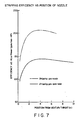
- FIG. 7 shows that although the oxygen removal rate was increased for the open tube injector plus venturi by moving the tube closer to the venturi throat, the fractional reduction of oxygen achieved using the tube injector plus venturi was always less than that for the high velocity nozzle injector plus venturi, at any given nozzle position. It is believed the size of stripping substance bubbles generated by the sonic shock wave within the water-oxygen-nitrogen composition may directly proportional to the size of the nitrogen stripping substance bubble entering the flow accelerating device prior to the sonic shock wave. The bubble exiting the open tube was considerably larger than that exiting the high pressure nozzle.
- a tapered nozzle provides extra momentum or velocity to the centerline of the stripping substance velocity profile, thereby assisting in the production of a more extensive shockwave within the composition, and generating smaller bubbles in a more uniform distribution across the venturi device configuration.
- the in-line tee shown in FIG. 1 comprised a pipe 2 having an inside diameter of about 0.82 inches and a tee joined pipe 4 having an inside diameter of about 0.82 inches.
- Room temperature water saturated with about 9 ppm of oxygen was fed into tee joined pipe 4 at a pressure of about 4 to 8 psig at a volumetric flow rate of about 3 gal/min (gpm).
- Room temperature nitrogen stripping gas having an oxygen concentration of about 1 ppm was fed into pipe 2 through a tube 6 having an inside diameter of about 0.25 inches.
- Tube 6 was spaced concentrically inside pipe 2. The end of tube 6 was placed approximately at the center of the inlet from tee joined pipe 4 into pipe 2, as shown in FIG. 1.
- the pressure of the room temperature nitrogen in tube 6 was about 4 to 8 psig.
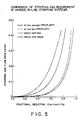
- the volumetric flow rate of nitrogen varied between about 0 standard cubic ft./min. (scfm) and about 0.5 scfm, as shown in FIG 5.
- the residence time of the water-oxygen-nitrogen composition within the in-line device was about 0.25 seconds and the residence time in downstream piping prior to sampling the water for oxygen content (Cout) was about 13 seconds.
- the fractional reduction of oxygen within the water for various nitrogen flow rates is shown in FIG 5.
- the fractional reduction of oxygen is equal to the oxygen concentration of the incoming water (Cin) minus the oxygen concentration of the processed water (Cout), measured at the end of the 500 inch long pipeline, the difference divided by the oxygen concentration of the incoming water (Cin).
- the data for the in-line tee of FIG. 1 is provided for comparison purposes only, since tee type gas-liquid mixing systems are known in the art.
- the in-line sparger arrangement shown in FIG. 2 comprised a pipe 10, having an inside diameter of about 0.82 inches and a tee joined pipe 12 having an inside diameter of about 0.82 inches.
- the sparging device 14 comprised a sintered metal cylinder with a porosity size of about 3 micrometers permitted gas flow out from within the cylinder.
- the sparging device 14 was positioned concentrically within pipe 10 so that about one half of the cylinder length extended on each side of the centerline of tee joined pipe 12, as shown in FIG. 2.
- Sparging device 14 was about 0.88 inches in length, having an outside diameter of about 0.5 inches.
- Room temperature water saturated at an oxygen concentration of about 9 ppm was fed into tee joined pipe 12 at a pressure of about 3 to 6 psig and at a volumetric flow rate of about 3 gpm.
- Room temperature nitrogen having an oxygen content of about 1 ppm was fed into sparging device 14 through an inlet tube 16.
- the nitrogen pressure in inlet tube 16 was less than about 40 psig, and the volumetric flow rate of the nitrogen was varied between about 0.0 and about 0.5 scfm as shown in FIG. 5.
- the residence time of the water-oxygen-nitrogen composition within the in-line device and downstream piping prior to analysis for processed water oxygen content was about the same as for the in-line tee.
- Oxygen was stripped from the incoming water by the nitrogen gas passing through the water.
- the fractional reduction in the oxygen concentration of the water at various nitrogen flow rates is shown in FIG. 5. This data is presented for comparison purposes only, as use of porous metal spargers to mix gas into a liquid is considered to be known in the art
- the in-line separation device shown in FIG. 3 comprised a pipe 20 about 0.82 inches in inside diameter, fitted with a venturi configuration 22 having a compression cone 24, a throat 26 and an expansion cone 28.
- the included angle 30 of compression cone 24 was about 21 degrees.
- the throat 26 was about 0.16 inches in diameter, having a throat length of about 0.16 inches.
- the included angle 32 of expansion cone 28 was about 15 degrees.
- Upstream of venturi configuration 22 was an open tube 34 which was positioned concentrically in the center of tube 20 through a sleeve 36 which extended through a cap 38 on the end of tube 20.
- a tee joined tube 40 extended from tube 20 upstream of venturi device 22 at a location near the entrance of open tube 34, as shown on FIG. 3.
- Open tube 34 had an inside diameter of about 0.18 inches and open tube 34 could be moved within sleeve 36 so that the position of the end 42 of tube 34 could be moved relative to venturi configuration 22.
- the position of the end 42 of tube 34 was about 7 inches from the beginning of venturi throat 26 at the time the data presented in FIG. 5 was gathered. At this location, the end 42 of tube 34 was upstream of the beginning of compression cone 24 by about 5.2 inches. Subsequent data has demonstrated the venturi with open tube device of FIG. 3 would have performed even better had the end 42 of tube 34 been positioned within compression cone 24.
- Room temperature water at a saturated oxygen concentration of about 9 ppm was fed into tee joined pipe 40 at a pressure of about 16 to 35 psig and at a volumetric flow rate of about about 3 gpm.
- Room temperature nitrogen having an oxygen concentration of about 1 ppm was fed through open tube 34 into pipe 20.
- the pressure in open tube 34 was less than about 40 psig, and the volumetric flow rate of nitrogen was varied between about 0.0 and about 0.5 scfm as shown in FIG. 5. Oxygen was stripped from the incoming water by the nitrogen gas passing through the water.
- the water-nitrogen composition downstream of open tube 34 was passed through venturi configuration 22 so that the linear velocity of the composition exiting venturi throat 26 ranged from about 50 ft/sec at zero nitrogen flow to about 112 ft/sec at 0.5 scfm of nitrogen flow.
- linear velocities as low as 50 ft/sec can provide theoretical supersonic velocity for the composition.
- the fractional reduction in the oxygen concentration of the water at various nitrogen flow rates is shown in FIG. 5. It is surprising to find such an improvement in fractional reduction for the venturi with tube over the prior art devices at nitrogen flow rates as low as 0.01 scfm.
- the calculated average linear velocity of the composition based on the data of Kieffer is below supersonic. This unexpected improvement in performance is attributed to the concept, previously discussed, that it is possible to have supersonic velocity at a particular point in the fluid flow profile within the device but not at another. Thus, the average linear velocity may be below theoretical supersonic flow, but a sonic shockwave may occur at point locations within the flow profile. Of course optimum device performance occurs when the average linear velocity is supersonic.
- the in-line separation device shown in FIG 4 comprised a pipe 50 about 0.82 inches in inside diameter, fitted with a venturi configuration 52 having a compression cone 54, a throat 56, and an expansion cone 58.
- the included angle of compression cone 54 was about 34 degrees.
- the throat 56 was about 0.19 inches in diameter, having a throat length of about 0.36 inches.
- Th included angle of expansion cone 58 was about 35 degrees.
- Upstream of venturi throat 56 was a nozzle section 60 extending from tube 62.
- Tube 62 was positioned concentrically in the center of pipe 50. During the early period of experimentation, tube 62 extended through a sleeve into an open housing area.
- the open housing area had an entering pipe and an exiting pipe, each about 0.82 inches in diameter; the center lines of the two pipes being at right angles, with the housing connecting them.
- Tube 62 extended through the housing with its centerline concentric to venturi throat 56.
- the housing section and entering pipe were replaced with a 90 degree long elbow 64 as shown in FIG. 4.
- Sleeve 66 extended through elbow 64 so that tube 62, including nozzle section 60 could be moved relative to venturi configuration 52.
- the inside diameter of pipe 50 entering and the inside diameter of elbow 64 were about 0.82 inches.
- Nozzle section 60 comprised an entrance inside diameter 68 of about 0.13 inches.
- a conical section 70 joined the entrance portion of the nozzle to the exit opening 72 which was about 0.063 inches in diameter.
- nozzle section 60 The details of nozzle section 60 are shown in FIG 4A.
- Room temperature water at a saturated oxygen concentration of about 9 ppm was fed into the entrance pipe through the open housing into pipe 50.
- the pressure in pipe 50 upstream of venturi configuration 52 was about 15 to 36 psig (15 psig at no nitrogen flow), at a volumetric flow rate of about 3 gpm.
- the pressure in pipe 50 upstream of venturi configuration 52 was reduced by about 3 to 6 psig at the volumetric flow rate of about 3 gpm with the benefit of elbow 64 in place, as shown in FIG 4.
- a single pass of the room-temperature water through the venturi with nozzle device provided a fractional reduction of about 0.94 at a flow rate of about 0.4 scfm nitrogen.
- the oxygen concentration was reduced from about 9 ppm to about 0.5 ppm.
- the in-line sparger of the type shown in FIG. 2 provided an oxygen concentration reduction from about 9 ppm to about 1.6 ppm at the 0.4 scfm nitrogen flow rate, and the in-line tee provided a reduction from about 9 ppm to about 2.2 ppm.
- the nitrogen usage rate becomes asymptomatical as the fractional reduction in oxygen content approaches 1.
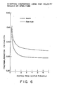
- FIG. 6 shows the effect of nozzle or open tube injector position relative to the venturi throat.
- the high velocity nozzle provides a better oxygen fractional reductions all other variables being substantially equivalent. This phenomenon is attributed to the smaller nitrogen bubble size leaving the nozzle as compared with the bubble size leaving the open tube and the increased linear velocity of the nitrogen at the center of the nozzle flow profile, as previously discussed.
- the data presented in FIG. 6 was generated using the open tube with venturi stripping device of FIG. 3 and the nozzle with venturi stripping device of FIG. 4, except that the open housing was present in the liquid flow line rather than the long 90° elbow shown in FIG. 4.
- Oxygen was stripped from room temperature water saturated at about 9 ppm of oxygen, using nitrogen having an oxygen content of about 1 ppm.
- the residence time in stripping device was about 19 seconds, including the residence time in the 500 inches of piping.
- the water flow rate was about 3 gpm, at a pressure raising from about 22 to 34 psig upstream of the stripping device, depending on the position of the nozzle relative to the venturi throat.
- the nitrogen flow rate was about 0.08 scfm at a pressure of less than about 40 psig in the tube leading to the open end exit or leading to the nozzle exit.
- the principal limiting factor in tube or nozzle location is the pressure drop across the system, measured as differential pressure across the inlet and outlet to the in-line device.
- the pressure drop increases as the tube or nozzle is moved closer to the venturi throat.
- the increase in pressure drop across the in-line stripping device is evidenced by the increased pumping power requirements necessary to maintain a given volumetric throughput rate for the liquid mixture.
- FIG. 7 shows one measure of the stripping efficiency for an in-line device. Efficiency, as mass transfer coefficient or mass transfer rate divided by pumping horsepower, is shown as a function of the stripping substance injection position relative to the venturi device throat entrance.
- the pressure drop across the tube with venturi device, with the tube end 42 positioned about 2 inches upstream of the entrance to venturi throat 26 was about 16 psi. This compared with a pressure drop of about 19 psi when tube end 42 was placed about one inch from the entrance to throat 26, compared with a pressure drop of about 23.5 psi when tube end 42 was placed about 0.5 inches from the entrance to the venturi throat 26.
- Pressure drops across the nozzle plus venturi device were about 16.5 psi when the nozzle was positioned about 2 inches from the entrance to venturi throat 26, about 20 psi when nozzle end 72 was positioned about one inch from venturi throat 26, and about 24 psi when nozzle end 72 was positioned about 0.5 inches from venturi throat 26.
- One skilled in the art desiring to use the present invention would consider the acceptable pressure drop (or cost of recovering pressure) in determining the practical location of the stripping substance injector relative to the entrance to the venturi throat. It is apparent from FIG. 7 that for a given throughput rate and liquid mixture-stripping substance composition, there is an optimum tube or nozzle position relative to the venturi configuration, in terms of stripping efficiency.
- Pressure drop can be reduced by increasing the venturi throat or minimum opening diameter or by reducing the diameter of the injector relative to the venturi throat or minimum opening diameter. This permits the injector to be positioned closer to the venturi throat or minimum opening diameter while holding the pressure drop constant.
- Pressure drop across the in-line device of the present invention also increases with increased loading of stripping substance in the mixture-stripping substance composition.
- the other factor which must be taken into account in determining overall system efficiency is the amount of stripping substance consumed to provide the necessary volatile component concentration in the processed mixture.
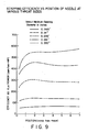
- FIG 8 shows the fractional reduction in oxygen content of room temperature water at various nitrogen flow rates, as a function of the minimum opening diameter (throat diameter in this case) of the venturi device.
- the data shown in FIG. 8 was generated using a venturi with nozzle type device similar to that shown in FIG. 4. Five different venturi configurations, each with a different throat diameter were evaluated. The length of each venturi throat was the same as its diameter. The compression cone and expansion cone included angles remained as previously described.
- the incoming room temperature water, oxygen concentration was about 10 ppm and the pressure in pipe 50 upstream of the stripping device ranged from about 19 psig at zero nitrogen flow for the smallest diameter throat to about 10 psig at zero nitrogen flow for the largest diameter throat.
- the water volumetric flow rate was about 3 gpm.
- the room temperature nitrogen stripping gas oxygen content was about 1 ppm.
- Some of the larger venturi throat sizes shown in FIG. 8 were designed to provide slightly less than theoretical subsonic linear flow velocity. For example, at a nitrogen volumetric flow:water volumetric flow of 1:1, and a water flow rate of about 3 gpm, the linear velocity of the water-oxygen-nitrogen composition through the largest throat diameter is about 20 ft/sec. This compares with 100 ft/sec for the smallest throat diameter at the same volumetric flow rates. Although the fractional oxygen reduction curves for the larger throat diameter do not follow the same shaped path as the curves for the smaller throat diameters, the clear performance distinction expected for theoretical subsonic flow compared with theoretical supersonic flow did not appear.
- each venturi configuration may generate supersonic flow along some flow paths within the configuration but not along others; Thus, although there was not supersonic flow across the entire device profile, there were localized shock waves in specific locations at which supersonic flow was achieved. As a result the oxygen removal achieved was better than expected.
- the calculated average linear flow velocity may be subsonic, but the velocity profile across the venturi throat is not constant due to wall effects, etc. and the linear velocity at the center of the profile may be supersonic.
- FIG. 9 shows the stripping efficiency corresponding to FIG. 8, as mass transfer coefficient divided by pumping horsepower, as a function of venturi throat size. There is an optimum venturi throat size for a given stripping application.
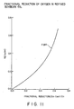
- Oxygen was separated from refined soybean oil using a nitrogen stripping gas in the stripping apparatus shown in FIG. 4.
- the fractional reduction of oxygen content in the soybean oil as a function of nitrogen stripping gas flow rate is shown in FIG. 11.
- the nitrogen injection nozzle was positioned about 0.25 inches upstream of the venturi throat, which was about 0.19 inches in diameter.
- the initial oxygen content of the soybean oil was about 37 ppm.
- the initial oxygen content of the room temperature nitrogen stripping gas was about 1 ppm.
- the soybean oil processing temperature was about 33°C
- the soybean oil flow rate was about 6 gpm
- the nitrogen flow rate was about 0.38 scfm
- a single pass through the stripping device decreased the oxygen content from the about 37 ppm to about 19 ppm.
- a second pass through the stripping device reduced the oxygen content in the soybean oil from the about 19 ppm to about 10 ppm.
- a single pass through the stripping device decreased the oxygen content from the about 37 ppm to about 11 ppm.
- the amount of nitrogen required to obtain a given fractional reduction in oxygen content of the soybean oil is considerably higher than that required for the same oxygen fractional reduction in water. Compare FIG. 11 with FIG. 5. This is because the soybean oil is a highly viscous liquid which reduces the oxygen diffusion rate from the 0.1 into the nitrogen stripping gas. In addition, the initial oxygen saturation concentration in soybean oil is about 4 times greater than the oxygen saturation in water at the same temperature. Nitrogen consumption is affected by the initial oxygen content of the soybean oil, the initial oxygen content of the nitrogen, the oil-nitrogen composition flow rate through the stripping device, and the composition temperature.
- Oxygen was removed from crude corn oil using the stripping apparatus shown in FIG. 4.
- the fractional reduction of oxygen content in the corn oil as a function of nitrogen stripping gas flow rate and corn oil flow rate is shown in FIG. 12.
- the nitrogen injection nozzle position and venturi throat diameter were the same as in EXAMPLE 4.
- the initial oxygen content of the corn oil was about 38 ppm.
- the initial oxygen content of the room temperature nitrogen stripping gas was about 1 ppm.
- the corn oil processing temperature was about 30°C.
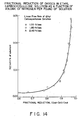
- the in-line stripping device shown in FIG. 4 was used to remove oxygen from an aqueous solution of ethyl carboxycellulose.
- the end of the nitrogen injection nozzle 70 was positioned about 0.25 inches upstream of the venturi throat which was about 0.19 inches in diameter and 0.36 inches in length.
- FIG. 14 shows the fractional reduction in oxygen content of an ethyl carboxycellulose solution as a function of nitrogen stripping gas loading and linear velocity of the solution-stripping gas composition through the in-line stripping device.
- the oxygen removal was carried out in a steady state, single stage stripping operation using an in-line device of the type shown in FIG. 4.
- the pipe size was about 0.82 inches in internal diameter, and the Cout oxygen concentration measurement was made downstream of the in-line stripping device, after 500 inch length of pipe.
- the system temperature was about 18°C and the viscosity of the ethyl carboxycellulose solution was about 5.5 cps.
- Molten aluminum reacts readily with moisture in the air forming hydrogen and aluminum oxide. Hydrogen will remain in the aluminum since it is quite soluble above the melting point of aluminum. The hydrogen must be removed from the molten metal before casting, otherwise cracks or voids may occurs when the hydrogen is driven off at the solidifying temperature of aluminum.
- the usual procedure for hydrogen removal is to bubble nitrogen, argon or mixtures of inert gases (with very low solubility) through a bath of the molten metal. The molten metal is then overflowed from the bath into a degassing unit where the gas bubbles will rise to the surface and be skimmed off. The inert gas will also remove particulates such as aluminum oxide or other solid impurities.
- the particulates will adhere to the inside of the gas bubbles due to surface tension. Particulate removal is a important part of the process.
- the batch process described above has very low stripping efficiency, however, because of back-mixing of low and high purity materials in this batch mode.
- the partial pressure of hydrogen in the gas phase is proportional to the square of the hydrogen concentration in the liquid phase. Therefore, the driving force in batch stripping operations becomes quite small as stripping continues.
- an in-line stripping device enables contacting a stripping gas with the molten aluminum when the molten aluminum is at its highest concentration of hydrogen and particulates. Therefore, the equilibrium driving forces will be maximized.
- Molten aluminum at about 700°C is pumped or pressure transferred from a melting pot through the in-line stripper to a degassing hold tank.
- the pump and pipings and the in-line stripping device are comprised of or are lined with refractory materials such as graphite, silicon nitrite, or silicon carbide, etc.
- Preferred stripping gases include nitrogen and argon. A small trace of chlorine may be added to the stripping gas to assist in removal of alkaline metals.
- Stripping gas at a volumetric flowrate of about 10 scfm is able to handle about 60,000 lb/hr of molten aluminum in a 2.5 inch diameter in-line stripping unit.
- Stripping gas consumption is about 19.9 scf/ton of aluminum.
- the optimized stripping gas consumption will vary depending on the concentration of the hydrogen in the molten aluminum; typically the hydrogen concentration ranges from about 0.1 to 0.4 cc/g.
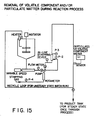
- FIG. 15 A process flow diagram for a typical, not intended to be limiting, system for stripping a dissolved high vapor pressure component from a reaction mixture is shown in FIG. 15.
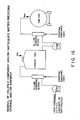
- FIG. 16 A process flow diagram for a typical, not intended to be limiting, system for removing a dissolved high vapor pressure component from a liquid to be stored and/or from a liquid to be shipped is shown in FIG. 16.
- Removal of a gas such as oxygen from a liquid to be stored can prevent oxidation of component parts of that liquid during the storage period.
Landscapes
- Chemical & Material Sciences (AREA)
- Chemical Kinetics & Catalysis (AREA)
- Organic Chemistry (AREA)
- Dispersion Chemistry (AREA)
- Water Supply & Treatment (AREA)
- Engineering & Computer Science (AREA)
- Environmental & Geological Engineering (AREA)
- Life Sciences & Earth Sciences (AREA)
- Hydrology & Water Resources (AREA)
- Health & Medical Sciences (AREA)
- Toxicology (AREA)
- Degasification And Air Bubble Elimination (AREA)
- Extraction Or Liquid Replacement (AREA)
- Processing Of Solid Wastes (AREA)
- Organic Low-Molecular-Weight Compounds And Preparation Thereof (AREA)
- Physical Water Treatments (AREA)
- Vaporization, Distillation, Condensation, Sublimation, And Cold Traps (AREA)
- Detergent Compositions (AREA)
Priority Applications (1)
| Application Number | Priority Date | Filing Date | Title |
|---|---|---|---|
| AT88121869T ATE90005T1 (de) | 1987-12-30 | 1988-12-29 | Trennungsverfahren eines bestandteils mit hohem dampfdruck und/oder besondere bestandteile von einem bestandteil mit niedrigem dampfdruck. |
Applications Claiming Priority (2)
| Application Number | Priority Date | Filing Date | Title |
|---|---|---|---|
| US139462 | 1980-04-11 | ||
| US07/139,462 US4861352A (en) | 1987-12-30 | 1987-12-30 | Method of separating a gas and/or particulate matter from a liquid |
Publications (3)
| Publication Number | Publication Date |
|---|---|
| EP0323646A2 true EP0323646A2 (fr) | 1989-07-12 |
| EP0323646A3 EP0323646A3 (en) | 1990-01-03 |
| EP0323646B1 EP0323646B1 (fr) | 1993-06-02 |
Family
ID=22486780
Family Applications (1)
| Application Number | Title | Priority Date | Filing Date |
|---|---|---|---|
| EP88121869A Expired - Lifetime EP0323646B1 (fr) | 1987-12-30 | 1988-12-29 | Procédé de séparation d'un composant ayant une pression de vapeur élevée et/ou une substance particulière d'un composant ayant une pression de vapeur basse |
Country Status (11)
| Country | Link |
|---|---|
| US (1) | US4861352A (fr) |
| EP (1) | EP0323646B1 (fr) |
| JP (1) | JPH01297105A (fr) |
| KR (1) | KR930001596B1 (fr) |
| AT (1) | ATE90005T1 (fr) |
| BR (1) | BR8806967A (fr) |
| CA (1) | CA1339617C (fr) |
| DE (1) | DE3881502T2 (fr) |
| ES (1) | ES2040827T3 (fr) |
| GR (1) | GR3008747T3 (fr) |
| MX (1) | MX168329B (fr) |
Cited By (11)
| Publication number | Priority date | Publication date | Assignee | Title |
|---|---|---|---|---|
| EP0494186A4 (en) * | 1989-09-25 | 1992-10-14 | Gaetano Russo | Improved process for oil decontamination |
| EP0565777A1 (fr) * | 1991-12-24 | 1993-10-20 | Praxair Technology, Inc. | Système d'extraction améliorée |
| DE19718921A1 (de) * | 1997-04-25 | 1997-11-27 | Ingbuero Kobert Und Partner Gm | Kompaktstripanlage zur Wasserreinigung |
| WO2001091877A3 (fr) * | 2000-05-31 | 2002-03-28 | Kraton Polymers Res Bv | Appareil et procede de production de polymere granulaire |
| WO2003093176A3 (fr) * | 2002-05-02 | 2003-12-18 | Mcnulty Peter Drummond | Systeme et procede de traitement des eaux |
| US6840983B2 (en) | 2002-05-02 | 2005-01-11 | Nei Treatment Systems, Llc | System and method of water treatment |
| EP1586369A1 (fr) * | 2004-04-13 | 2005-10-19 | Paul Scherrer Institut | Appareillage pour générer des bulles fines de gaz dans un liquide |
| FR3003769A1 (fr) * | 2013-04-02 | 2014-10-03 | Antea France | Systeme de stripeur dynamique |
| US9061925B2 (en) | 2006-10-20 | 2015-06-23 | Oceansaver As | Liquid treatment methods and apparatus |
| WO2016046016A1 (fr) * | 2014-09-26 | 2016-03-31 | Odor Control Europe Ab | Dispositif pour le traitement d'eaux usées |
| US10144904B2 (en) | 2015-12-04 | 2018-12-04 | Evonik Degussa Gmbh | Process for extraction of aroma chemicals from fat-containing and/or aqueous liquid phases |
Families Citing this family (32)
| Publication number | Priority date | Publication date | Assignee | Title |
|---|---|---|---|---|
| US5057658A (en) * | 1989-02-27 | 1991-10-15 | Micron Technology, Inc. | Apparatus for oil filtration and recirculation |
| US5015273A (en) * | 1990-03-16 | 1991-05-14 | Camco International Inc. | Foam breaker and method |
| US5302325A (en) * | 1990-09-25 | 1994-04-12 | Praxair Technology, Inc. | In-line dispersion of gas in liquid |
| US5061406A (en) * | 1990-09-25 | 1991-10-29 | Union Carbide Industrial Gases Technology Corporation | In-line gas/liquid dispersion |
| USH1206H (en) | 1991-01-24 | 1993-07-06 | The United States Of America As Represented By The Secretary Of The Air Force | Cascade crossflow tower |
| JPH05184811A (ja) * | 1991-12-27 | 1993-07-27 | Iwatani Internatl Corp | 液体中からの脱酸素方法 |
| US5403475A (en) * | 1993-01-22 | 1995-04-04 | Allen; Judith L. | Liquid decontamination method |
| DE9302862U1 (de) * | 1993-02-26 | 1993-05-27 | Anton Steinecker Entwicklungs GmbH & Co, 8050 Freising | Belüftungsdüse zum Belüften von organische Substanzen enthaltenden Flüssigkeiten |
| US5354459A (en) * | 1993-03-19 | 1994-10-11 | Jerry Smith | Apparatus and method for removing odorous sulfur compounds from potable water |
| US5532389A (en) * | 1993-11-23 | 1996-07-02 | The Dow Chemical Company | Process for preparing alkylene oxides |
| US5980613A (en) * | 1996-02-20 | 1999-11-09 | Hdr Engineering, Inc. | Pressurized radon stripper |
| US5744040A (en) * | 1996-05-24 | 1998-04-28 | Sulfur-Tech Water Systems, Inc. | Apparatus and method for removing dissolved hydrogen sulfide from water |
| CA2262108C (fr) * | 1996-07-26 | 2004-01-06 | Metaullics Systems Co., L.P. | Pompe de gazage |
| JP3533332B2 (ja) * | 1998-05-20 | 2004-05-31 | Tdk株式会社 | 電子部品の製造方法および水処理装置 |
| US6103108A (en) * | 1998-09-24 | 2000-08-15 | Kohlenberg; Larry D. | Water treatment apparatus |
| US6250609B1 (en) | 1999-06-30 | 2001-06-26 | Praxair Technology, Inc. | Method of making supersaturated oxygenated liquid |
| US6372024B1 (en) * | 2000-06-07 | 2002-04-16 | Russell E. Prescott | System and method for removing contaminating gases from water |
| US20040231513A1 (en) * | 2002-03-12 | 2004-11-25 | Perkins James A. | System for inline stripping of soil contaminants |
| US8322430B2 (en) * | 2005-06-03 | 2012-12-04 | Shell Oil Company | Pipes, systems, and methods for transporting fluids |
| US20070126132A1 (en) * | 2005-12-07 | 2007-06-07 | Galgano Mark A | Vena contracta |
| US20090032446A1 (en) * | 2007-08-01 | 2009-02-05 | Triwatech, L.L.C. | Mobile station and methods for diagnosing and modeling site specific effluent treatment facility requirements |
| JP2012517671A (ja) | 2009-02-08 | 2012-08-02 | エーピー ソルーションズ, インコーポレイテッド | 圧力波を利用して基板から材料を除去するためのプラズマ源および方法 |
| GB2474559A (en) * | 2009-10-13 | 2011-04-20 | Bp Corp North America Inc | Deaeration of water |
| US8245882B1 (en) * | 2009-12-18 | 2012-08-21 | Federighi William D | Pouring spout for aerating poured liquid |
| US8449656B2 (en) * | 2010-11-16 | 2013-05-28 | Amt International Inc. | Process and apparatus for removal of oxygen from seawater |
| US20120156345A1 (en) * | 2010-12-20 | 2012-06-21 | Dhruv Agarwal | Bottle top aerator |
| US20120295333A1 (en) * | 2011-05-19 | 2012-11-22 | Cheng Alan T | Systems and methods for producing a gas dispersion in a biological substance in a disposable vessel |
| US9272766B2 (en) * | 2012-09-20 | 2016-03-01 | Sea Knight Corporation | “In-situ” ballast water treatment method and system |
| USD705598S1 (en) | 2012-11-22 | 2014-05-27 | David M. Prokop | Aerator pourer device |
| WO2014160870A1 (fr) | 2013-03-28 | 2014-10-02 | Cummins Filtration Ip, Inc. | Séparateur air-huile avec un impact amélioré par projection et procédé associé |
| DE102016015322A1 (de) | 2016-12-22 | 2018-06-28 | Messer Group Gmbh | Vorrichtung und Verfahren zum Eintragen von Gas in eine Mehrzahl von Prozessfluiden |
| WO2025067193A1 (fr) * | 2023-09-25 | 2025-04-03 | 中国石油化工股份有限公司 | Séparateur venturi et son utilisation |
Family Cites Families (23)
| Publication number | Priority date | Publication date | Assignee | Title |
|---|---|---|---|---|
| US1255018A (en) * | 1916-03-30 | 1918-01-29 | Philip Jones | Process and apparatus for the separation of oils and gases. |
| US2413102A (en) * | 1941-11-25 | 1946-12-24 | American Viscose Corp | Degasifier |
| US3132013A (en) * | 1959-10-03 | 1964-05-05 | Yawata Iron & Steel Co | Process for treating feed water |
| DE1209773B (de) * | 1962-07-27 | 1966-01-27 | Rheinmetall Gmbh | Verfahren zum Erzeugen von Stroemungen hoher Machzahlen |
| GB1156417A (en) * | 1966-09-28 | 1969-06-25 | British Oxygen Co Ltd | Deoxygenation of Liquids |
| FR2084292A5 (fr) * | 1970-03-06 | 1971-12-17 | Dresser Ind | |
| US3732668A (en) * | 1971-02-24 | 1973-05-15 | Parker Hannifin Corp | Fuel tank inerting system |
| CA1011089A (en) * | 1973-03-26 | 1977-05-31 | Lawrence C. Baughman | Method of stripping volatile material from an aqueous dispersion of polymeric substance |
| AU7074874A (en) * | 1973-07-09 | 1976-01-08 | Envirotech Corp | Supersonic small bubble generation |
| GB1531537A (en) * | 1976-03-26 | 1978-11-08 | British Petroleum Co | Degassing treatment of liquid |
| US4017276A (en) * | 1976-06-22 | 1977-04-12 | The Lummus Company | Deoxygenation of water |
| US4259360A (en) * | 1979-04-16 | 1981-03-31 | Liquid Carbonic Corporation | Deoxygenation of liquids |
| CH641839A5 (de) * | 1979-07-10 | 1984-03-15 | Alusuisse | Vorrichtung zur einleitung von gasen in metallschmelzen. |
| JPS56121681A (en) * | 1980-02-29 | 1981-09-24 | Mitsubishi Heavy Ind Ltd | Treatment of open type softened cooling water |
| US4352682A (en) * | 1980-11-13 | 1982-10-05 | Fmc Corporation | Deoxygenating apparatus |
| JPS58133885A (ja) * | 1982-02-01 | 1983-08-09 | Toray Eng Co Ltd | 液中の溶存酸素を除去する方法 |
| NO152209C (no) * | 1982-09-13 | 1985-08-28 | Norsk Hydro As | Fremgangsmaate ved pumping og avgassing av vann |
| JPS59154109A (ja) * | 1983-02-23 | 1984-09-03 | Hitachi Ltd | 脱気装置 |
| GB2145937A (en) * | 1983-07-07 | 1985-04-11 | British Hydromechanics | Contacting a gas and a liquid to remove an unwanted gas |
| GB8401779D0 (en) * | 1984-01-24 | 1984-02-29 | Boc Group Plc | Dissolving gas liquid |
| JPS60183012A (ja) * | 1984-03-01 | 1985-09-18 | Mitsubishi Heavy Ind Ltd | スチ−ムコンバ−タ装置 |
| FR2570286A1 (fr) * | 1984-09-17 | 1986-03-21 | Sofrechim Sarl | Appareillage de deshydratation de solution destine en particulier a la production d'acide super phosphorique |
| BR8503919A (pt) * | 1985-08-16 | 1987-03-24 | Liquid Carbonic Ind Sa | Ejetor para o processo co2 na neutralizacao de aguas alcalinas |
-
1987
- 1987-12-30 US US07/139,462 patent/US4861352A/en not_active Expired - Lifetime
-
1988
- 1988-12-28 JP JP63332701A patent/JPH01297105A/ja active Granted
- 1988-12-29 MX MX014379A patent/MX168329B/es unknown
- 1988-12-29 EP EP88121869A patent/EP0323646B1/fr not_active Expired - Lifetime
- 1988-12-29 KR KR8818219A patent/KR930001596B1/ko not_active Expired - Fee Related
- 1988-12-29 AT AT88121869T patent/ATE90005T1/de not_active IP Right Cessation
- 1988-12-29 DE DE8888121869T patent/DE3881502T2/de not_active Expired - Fee Related
- 1988-12-29 ES ES198888121869T patent/ES2040827T3/es not_active Expired - Lifetime
- 1988-12-29 CA CA000587219A patent/CA1339617C/fr not_active Expired - Fee Related
- 1988-12-29 BR BR888806967A patent/BR8806967A/pt not_active IP Right Cessation
-
1993
- 1993-08-16 GR GR930400027T patent/GR3008747T3/el unknown
Cited By (15)
| Publication number | Priority date | Publication date | Assignee | Title |
|---|---|---|---|---|
| EP0494186A4 (en) * | 1989-09-25 | 1992-10-14 | Gaetano Russo | Improved process for oil decontamination |
| EP0565777A1 (fr) * | 1991-12-24 | 1993-10-20 | Praxair Technology, Inc. | Système d'extraction améliorée |
| DE19718921A1 (de) * | 1997-04-25 | 1997-11-27 | Ingbuero Kobert Und Partner Gm | Kompaktstripanlage zur Wasserreinigung |
| WO2001091877A3 (fr) * | 2000-05-31 | 2002-03-28 | Kraton Polymers Res Bv | Appareil et procede de production de polymere granulaire |
| KR101006763B1 (ko) * | 2002-05-02 | 2011-01-10 | 피터 드러몬드 맥널티 | 수처리 시스템 및 방법 |
| US6840983B2 (en) | 2002-05-02 | 2005-01-11 | Nei Treatment Systems, Llc | System and method of water treatment |
| US7374602B2 (en) | 2002-05-02 | 2008-05-20 | Nei Treatment Systems, Llc | System and method of water treatment |
| WO2003093176A3 (fr) * | 2002-05-02 | 2003-12-18 | Mcnulty Peter Drummond | Systeme et procede de traitement des eaux |
| EP1586369A1 (fr) * | 2004-04-13 | 2005-10-19 | Paul Scherrer Institut | Appareillage pour générer des bulles fines de gaz dans un liquide |
| WO2005099888A1 (fr) * | 2004-04-13 | 2005-10-27 | Paul Scherrer Institut | Appareil permettant de produire de fines bulles de gaz dans un liquide |
| US9061925B2 (en) | 2006-10-20 | 2015-06-23 | Oceansaver As | Liquid treatment methods and apparatus |
| US9255017B2 (en) | 2006-10-20 | 2016-02-09 | Oceansaver As | Liquid treatment methods and apparatus |
| FR3003769A1 (fr) * | 2013-04-02 | 2014-10-03 | Antea France | Systeme de stripeur dynamique |
| WO2016046016A1 (fr) * | 2014-09-26 | 2016-03-31 | Odor Control Europe Ab | Dispositif pour le traitement d'eaux usées |
| US10144904B2 (en) | 2015-12-04 | 2018-12-04 | Evonik Degussa Gmbh | Process for extraction of aroma chemicals from fat-containing and/or aqueous liquid phases |
Also Published As
| Publication number | Publication date |
|---|---|
| KR890009444A (ko) | 1989-08-02 |
| EP0323646A3 (en) | 1990-01-03 |
| EP0323646B1 (fr) | 1993-06-02 |
| KR930001596B1 (en) | 1993-03-06 |
| JPH0586242B2 (fr) | 1993-12-10 |
| DE3881502D1 (de) | 1993-07-08 |
| GR3008747T3 (fr) | 1993-11-30 |
| ATE90005T1 (de) | 1993-06-15 |
| ES2040827T3 (es) | 1993-11-01 |
| DE3881502T2 (de) | 1993-09-23 |
| MX168329B (es) | 1993-05-18 |
| JPH01297105A (ja) | 1989-11-30 |
| US4861352A (en) | 1989-08-29 |
| CA1339617C (fr) | 1998-01-06 |
| BR8806967A (pt) | 1989-08-29 |
Similar Documents
| Publication | Publication Date | Title |
|---|---|---|
| EP0323646B1 (fr) | Procédé de séparation d'un composant ayant une pression de vapeur élevée et/ou une substance particulière d'un composant ayant une pression de vapeur basse | |
| US4931225A (en) | Method and apparatus for dispersing a gas into a liquid | |
| US4639340A (en) | Dissolving gas in a liquid | |
| US10710033B2 (en) | Multi fluid injection mixer | |
| EP0211492B1 (fr) | Procédé et dispositif pour la réduction de la teneur en huile des eaux usées par flottation au gaz | |
| US3759669A (en) | Apparatus for contacting liquid and solid particles | |
| EP0322925B1 (fr) | Procédé pour disperser du gaz | |
| JP2004534875A (ja) | 浮揚性構造物上にて実施されるフィッシャー−トロプシュ合成方法 | |
| CN101330954B (zh) | 重力分离器和用于分离含有水、油以及气体的混合物的方法 | |
| CN113926324A (zh) | 一种利用二氧化碳液气相变制备微泡的方法及微泡的应用 | |
| US4900452A (en) | Separation process for a liquid phase dispersed in a continuous liquid phase | |
| Huynh et al. | Hydrodynamics and mass transfer in an upward venturi/bubble column combination | |
| US12251669B2 (en) | Shear flow nanobubble generator | |
| WO2020028646A1 (fr) | Appareil et procédé d'expansion de nano-bulles dans un support liquide | |
| Bando et al. | Flow characteristics in cocurrent upflow bubble column dispersed with micro-bubbles | |
| CN101678245A (zh) | 用于分离油/水混合物的方法和装置 | |
| CN106277150B (zh) | 一种石油水处理用气浮选微气泡加气装置及其使用方法 | |
| US4260398A (en) | Countercurrent sparger | |
| Rawase et al. | Gas—liauid mass transfer in three‐phase stirred tank reagors: Newtonian and non‐newtonian fluids | |
| Sovilj et al. | Gas-agitated liquid-liquid extraction in a spray column | |
| US5632932A (en) | Distribution of fine bubbles or droplets in a liquid | |
| US20070035048A1 (en) | Method and equipment for mixing fluids | |
| US7121534B2 (en) | Method and apparatus for gasifying a liquid | |
| US20160361692A1 (en) | Process and device for dispersing gas in a liquid | |
| Xiong et al. | Effects of gas‐agitation and packing on hydrodynamics and mass transfer of extraction column |
Legal Events
| Date | Code | Title | Description |
|---|---|---|---|
| PUAI | Public reference made under article 153(3) epc to a published international application that has entered the european phase |
Free format text: ORIGINAL CODE: 0009012 |
|
| AK | Designated contracting states |
Kind code of ref document: A2 Designated state(s): AT BE CH DE ES FR GB GR IT LI LU NL SE |
|
| PUAL | Search report despatched |
Free format text: ORIGINAL CODE: 0009013 |
|
| AK | Designated contracting states |
Kind code of ref document: A3 Designated state(s): AT BE CH DE ES FR GB GR IT LI LU NL SE |
|
| 17P | Request for examination filed |
Effective date: 19900115 |
|
| 17Q | First examination report despatched |
Effective date: 19911030 |
|
| ITF | It: translation for a ep patent filed | ||
| GRAA | (expected) grant |
Free format text: ORIGINAL CODE: 0009210 |
|
| AK | Designated contracting states |
Kind code of ref document: B1 Designated state(s): AT BE CH DE ES FR GB GR IT LI LU NL SE |
|
| RAP1 | Party data changed (applicant data changed or rights of an application transferred) |
Owner name: PRAXAIR TECHNOLOGY, INC. |
|
| REF | Corresponds to: |
Ref document number: 90005 Country of ref document: AT Date of ref document: 19930615 Kind code of ref document: T |
|
| REF | Corresponds to: |
Ref document number: 3881502 Country of ref document: DE Date of ref document: 19930708 |
|
| ET | Fr: translation filed | ||
| REG | Reference to a national code |
Ref country code: GR Ref legal event code: FG4A Free format text: 3008747 |
|
| REG | Reference to a national code |
Ref country code: ES Ref legal event code: FG2A Ref document number: 2040827 Country of ref document: ES Kind code of ref document: T3 |
|
| EPTA | Lu: last paid annual fee | ||
| PLBE | No opposition filed within time limit |
Free format text: ORIGINAL CODE: 0009261 |
|
| STAA | Information on the status of an ep patent application or granted ep patent |
Free format text: STATUS: NO OPPOSITION FILED WITHIN TIME LIMIT |
|
| 26N | No opposition filed | ||
| EAL | Se: european patent in force in sweden |
Ref document number: 88121869.7 |
|
| PGFP | Annual fee paid to national office [announced via postgrant information from national office to epo] |
Ref country code: SE Payment date: 19951110 Year of fee payment: 8 |
|
| PGFP | Annual fee paid to national office [announced via postgrant information from national office to epo] |
Ref country code: AT Payment date: 19951114 Year of fee payment: 8 |
|
| PGFP | Annual fee paid to national office [announced via postgrant information from national office to epo] |
Ref country code: NL Payment date: 19951122 Year of fee payment: 8 |
|
| PGFP | Annual fee paid to national office [announced via postgrant information from national office to epo] |
Ref country code: CH Payment date: 19951123 Year of fee payment: 8 |
|
| PGFP | Annual fee paid to national office [announced via postgrant information from national office to epo] |
Ref country code: GB Payment date: 19951124 Year of fee payment: 8 |
|
| PGFP | Annual fee paid to national office [announced via postgrant information from national office to epo] |
Ref country code: GR Payment date: 19951128 Year of fee payment: 8 |
|
| PGFP | Annual fee paid to national office [announced via postgrant information from national office to epo] |
Ref country code: LU Payment date: 19951201 Year of fee payment: 8 |
|
| PG25 | Lapsed in a contracting state [announced via postgrant information from national office to epo] |
Ref country code: LU Free format text: LAPSE BECAUSE OF NON-PAYMENT OF DUE FEES Effective date: 19961229 Ref country code: GB Effective date: 19961229 Ref country code: AT Effective date: 19961229 |
|
| PG25 | Lapsed in a contracting state [announced via postgrant information from national office to epo] |
Ref country code: SE Effective date: 19961230 |
|
| PG25 | Lapsed in a contracting state [announced via postgrant information from national office to epo] |
Ref country code: LI Effective date: 19961231 Ref country code: CH Effective date: 19961231 |
|
| PG25 | Lapsed in a contracting state [announced via postgrant information from national office to epo] |
Ref country code: GR Free format text: THE PATENT HAS BEEN ANNULLED BY A DECISION OF A NATIONAL AUTHORITY Effective date: 19970630 |
|
| PG25 | Lapsed in a contracting state [announced via postgrant information from national office to epo] |
Ref country code: NL Effective date: 19970701 |
|
| REG | Reference to a national code |
Ref country code: GR Ref legal event code: MM2A Free format text: 3008747 |
|
| REG | Reference to a national code |
Ref country code: CH Ref legal event code: PL |
|
| GBPC | Gb: european patent ceased through non-payment of renewal fee |
Effective date: 19961229 |
|
| NLV4 | Nl: lapsed or anulled due to non-payment of the annual fee |
Effective date: 19970701 |
|
| EUG | Se: european patent has lapsed |
Ref document number: 88121869.7 |
|
| PGFP | Annual fee paid to national office [announced via postgrant information from national office to epo] |
Ref country code: FR Payment date: 20011130 Year of fee payment: 14 |
|
| PGFP | Annual fee paid to national office [announced via postgrant information from national office to epo] |
Ref country code: DE Payment date: 20011204 Year of fee payment: 14 |
|
| PGFP | Annual fee paid to national office [announced via postgrant information from national office to epo] |
Ref country code: BE Payment date: 20011224 Year of fee payment: 14 |
|
| PGFP | Annual fee paid to national office [announced via postgrant information from national office to epo] |
Ref country code: ES Payment date: 20020109 Year of fee payment: 14 |
|
| PG25 | Lapsed in a contracting state [announced via postgrant information from national office to epo] |
Ref country code: ES Free format text: LAPSE BECAUSE OF NON-PAYMENT OF DUE FEES Effective date: 20021230 |
|
| PG25 | Lapsed in a contracting state [announced via postgrant information from national office to epo] |
Ref country code: BE Free format text: LAPSE BECAUSE OF NON-PAYMENT OF DUE FEES Effective date: 20021231 |
|
| BERE | Be: lapsed |
Owner name: *PRAXAIR TECHNOLOGY INC. Effective date: 20021231 |
|
| PG25 | Lapsed in a contracting state [announced via postgrant information from national office to epo] |
Ref country code: DE Free format text: LAPSE BECAUSE OF NON-PAYMENT OF DUE FEES Effective date: 20030701 |
|
| PG25 | Lapsed in a contracting state [announced via postgrant information from national office to epo] |
Ref country code: FR Free format text: LAPSE BECAUSE OF NON-PAYMENT OF DUE FEES Effective date: 20030901 |
|
| REG | Reference to a national code |
Ref country code: FR Ref legal event code: ST |
|
| REG | Reference to a national code |
Ref country code: ES Ref legal event code: FD2A Effective date: 20021230 |
|
| PG25 | Lapsed in a contracting state [announced via postgrant information from national office to epo] |
Ref country code: IT Free format text: LAPSE BECAUSE OF NON-PAYMENT OF DUE FEES;WARNING: LAPSES OF ITALIAN PATENTS WITH EFFECTIVE DATE BEFORE 2007 MAY HAVE OCCURRED AT ANY TIME BEFORE 2007. THE CORRECT EFFECTIVE DATE MAY BE DIFFERENT FROM THE ONE RECORDED. Effective date: 20051229 |