EP0323706A2 - Dispositif pour la fermeture et le scellement d'enveloppes, enveloppe et enveloppe munie d'un dispositif de fermeture et de scellement - Google Patents
Dispositif pour la fermeture et le scellement d'enveloppes, enveloppe et enveloppe munie d'un dispositif de fermeture et de scellement Download PDFInfo
- Publication number
- EP0323706A2 EP0323706A2 EP88311175A EP88311175A EP0323706A2 EP 0323706 A2 EP0323706 A2 EP 0323706A2 EP 88311175 A EP88311175 A EP 88311175A EP 88311175 A EP88311175 A EP 88311175A EP 0323706 A2 EP0323706 A2 EP 0323706A2
- Authority
- EP
- European Patent Office
- Prior art keywords
- envelope
- orifices
- flap
- parts
- sealing
- Prior art date
- Legal status (The legal status is an assumption and is not a legal conclusion. Google has not performed a legal analysis and makes no representation as to the accuracy of the status listed.)
- Withdrawn
Links
Images



Classifications
-
- B—PERFORMING OPERATIONS; TRANSPORTING
- B65—CONVEYING; PACKING; STORING; HANDLING THIN OR FILAMENTARY MATERIAL
- B65D—CONTAINERS FOR STORAGE OR TRANSPORT OF ARTICLES OR MATERIALS, e.g. BAGS, BARRELS, BOTTLES, BOXES, CANS, CARTONS, CRATES, DRUMS, JARS, TANKS, HOPPERS, FORWARDING CONTAINERS; ACCESSORIES, CLOSURES, OR FITTINGS THEREFOR; PACKAGING ELEMENTS; PACKAGES
- B65D27/00—Envelopes or like essentially-rectangular flexible containers for postal or other purposes having no structural provision for thickness of contents
- B65D27/12—Closures
- B65D27/30—Closures with special means for indicating unauthorised opening
-
- Y—GENERAL TAGGING OF NEW TECHNOLOGICAL DEVELOPMENTS; GENERAL TAGGING OF CROSS-SECTIONAL TECHNOLOGIES SPANNING OVER SEVERAL SECTIONS OF THE IPC; TECHNICAL SUBJECTS COVERED BY FORMER USPC CROSS-REFERENCE ART COLLECTIONS [XRACs] AND DIGESTS
- Y10—TECHNICAL SUBJECTS COVERED BY FORMER USPC
- Y10T—TECHNICAL SUBJECTS COVERED BY FORMER US CLASSIFICATION
- Y10T24/00—Buckles, buttons, clasps, etc.
- Y10T24/15—Bag fasteners
-
- Y—GENERAL TAGGING OF NEW TECHNOLOGICAL DEVELOPMENTS; GENERAL TAGGING OF CROSS-SECTIONAL TECHNOLOGIES SPANNING OVER SEVERAL SECTIONS OF THE IPC; TECHNICAL SUBJECTS COVERED BY FORMER USPC CROSS-REFERENCE ART COLLECTIONS [XRACs] AND DIGESTS
- Y10—TECHNICAL SUBJECTS COVERED BY FORMER USPC
- Y10T—TECHNICAL SUBJECTS COVERED BY FORMER US CLASSIFICATION
- Y10T24/00—Buckles, buttons, clasps, etc.
- Y10T24/44—Clasp, clip, support-clamp, or required component thereof
- Y10T24/44641—Clasp, clip, support-clamp, or required component thereof having gripping member formed from, biased by, or mounted on resilient member
- Y10T24/44744—Clasp, clip, support-clamp, or required component thereof having gripping member formed from, biased by, or mounted on resilient member with position locking-means for engaging faces
- Y10T24/44752—Integral locking-means
-
- Y—GENERAL TAGGING OF NEW TECHNOLOGICAL DEVELOPMENTS; GENERAL TAGGING OF CROSS-SECTIONAL TECHNOLOGIES SPANNING OVER SEVERAL SECTIONS OF THE IPC; TECHNICAL SUBJECTS COVERED BY FORMER USPC CROSS-REFERENCE ART COLLECTIONS [XRACs] AND DIGESTS
- Y10—TECHNICAL SUBJECTS COVERED BY FORMER USPC
- Y10T—TECHNICAL SUBJECTS COVERED BY FORMER US CLASSIFICATION
- Y10T24/00—Buckles, buttons, clasps, etc.
- Y10T24/50—Readily interlocking, two-part fastener requiring either destructive or tool disengagement
-
- Y—GENERAL TAGGING OF NEW TECHNOLOGICAL DEVELOPMENTS; GENERAL TAGGING OF CROSS-SECTIONAL TECHNOLOGIES SPANNING OVER SEVERAL SECTIONS OF THE IPC; TECHNICAL SUBJECTS COVERED BY FORMER USPC CROSS-REFERENCE ART COLLECTIONS [XRACs] AND DIGESTS
- Y10—TECHNICAL SUBJECTS COVERED BY FORMER USPC
- Y10T—TECHNICAL SUBJECTS COVERED BY FORMER US CLASSIFICATION
- Y10T292/00—Closure fasteners
- Y10T292/48—Seals
- Y10T292/4945—Rigid shackle ends
- Y10T292/496—Resilient engaging means
Definitions
- a plastic envelope for the transport of money or confidential documents which is closed by means of an adhesive which supposedly prevents re-opening of the envelope without visibly adulterating the envelope.
- a product is indiscussably simple to close, unfortunately it is relatively simple to wet the adhesive with solvent, open the envelope and then close it again, it only being necessary to evaporate the solvent for the adhesive to return to its original condition without leaving any visible sign of tampering.
- a device for the closing and sealing of envelopes comprises first and second substantially planar parts, a surface of the first part being provided with a plurality of male elements upstanding therefrom and a corresponding surface provided on the second part having a corresponding plurality of locking formations for receiving and locking said male elements, the scale elements being connected at their bases to said surface of the first part by means of weakened connections visible from the opposite surface of the first part through corresponding orifices in said first part.
- first and second parts are hinged to each other and may be molded as a single piece from plastics material.
- At least one and preferably both parts are provided with fixing means for fixing them to the material of the envelope to be closed and sealed.
- an envelope for use with the above closing and sealing device is characterized by comprising a closed end, a transverse opening in the region of the other end and a flap which extends beyond the opening in the form of a continuation of at least one side of the envelope, a first plura lity of through orifices distributed transversally along and adjacent to the free edge of the flap, a second corresponding plurality of orifices distributed transversally across the flap adjacent said opening, and a third corresponding plurality of orifices distributed transversally along and adjacent to said opening, on the same side of said opening as the enclosed end.
- the invention refers to an envelope of the type defined above having mounted thereon the above described closing and sealing device, said envelope being characterized in that said two parts of the device are wrapped in said flap of the envelope with the said plurality of male elements passing first through the first plurality of openings in the flap, towards the side of the envelope having the opening, and then through the third plurality of openings in the envelope, the openings of the second plurality in the flap being in register with the entrances of the female formations on said second part of the device and the weakenings at the bases of the male elements being visible through the flap of the envelope.
- each fixing means may comprise a tongue bent and fixed in a position substantially in the plane of the respective part of the device and the corresponding orifices comprise a pair of rectangular orifices defining therebetween a strip of the material of the flap of the envelope caught by the tongue which passes in one direction through one of the orifices and in the opposite direction through the other orifice of the pair before being fixed.
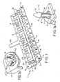
- a device for closing and sealing envelopes in the form of a preferred embodiment of the present invention, comprises a single piece 1 constituted of two elongate rectangular parts 2 and 3, interconnected by small bridges 4. Bridges 4 serve to define a hinge so that part 3 may be hinged over part 2.
- a plurality of pins 5 is formed along that edge of part 2 which is remote from the bridges 4 which define the hinge. Pins 5, as shown in Figure 1, are distributed equidistantly and linearly along said edge.
- Figure 1a shows a pin 5 in detail, it being observed that it has a conical head 6 and a cylindrical body 7 with three vertical ribs 8 whose outer surfaces comprise a continuation of head 6.
- the diameter of body 7 is smaller than the diameter of the base of head 6, so that the lower edge of the head, between ribs 8, defines lips or negative surfaces 9.
- Part 2 of the device is formed with an orifice 10 in the region of the base of each pin 5.
- the largest diameter of pin 5 is smaller than the diameter of orifice 10, the pin be ing fixed to part 2 by weakened radial connections between the inside edge of orifice 10 and the lower ends of ribs 8.
- Part 2 of piece 1 is also formed with a series of rectangular openings 12 distributed along its length, whose only funtion is to reduce the quantity of material (plastic) to be used in the manufacture of the device.
- part 3 has openings 13.
- pins 14 formed between pins 6 of the first plurality.
- Such pins 14 have only a positioning function and are cylindrical with generally conical ends.
- Part 3 of piece 1 is formed along its edge opposite to the hinge bridges 4 with a plurality of femal formations 15 distributed equidistantly and linearly at positions corresponding to those of pins 5 on part 2.
- the formations 15 are formed in such a way that, on bending part 3 over part 2, each pin 5 will penetrate its corresponding female formation 15 which will lock it therein in a tamper-proof manner, that is to say, so that the pin cannot be withdrawn from the formation and the separation of parts 2 and 3 will result in the rupture of the weakened connections 11 at the base of pin 5.
- Figure 1b shows a detail of a female formation 15 which comprises, in reality, a circular orifice 15 in part 3 and three tongues 17 which project across the lower surface of part 3, such tongues being inclined downwardly and inwardly so as to define three locking edges 18 corresponding to the lips or negative surfaces 9 below head 6 on pin 5.
- parts 2 and 3 are provided with small upstanding tongues 20, those on part 2 facing pins 5 and those on part 3 facing along the lenth of the device.
- Each tongue 20 may be bent so as to lie in the plane of the respective part 2 or 3.
- the edge 21 of the opening opposite that of the base of tongue 20 limiting the dimension of the opening to be slightly less than the length of the tongue.
- its free end 22 may be forced passed edge 21 of the opening, after which it will remain caught in that position (see Figure 6).
- Tongues 20 serve to secure device 1 to an envelope to be closed and sealed.
- part 3 is provided with an identifying tab 23 which may be numbered to individualize the respective device.
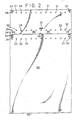
- Figure 2 shows an envelope manufactured especially for use with the device illustrated in Figure 1.
- Figure 2 shows it as if it were made of transparent plastic material so as to facilitate an understanding of the drawings. It should, however, be understood that there is no necessity for the envelope to be transparent and this would not normally be advisable with respect to the body thereof, mainly because this would provide a visibility of its contents. At the same time, and as will be mentioned later, there is a necessity for at least part of the upper flap of the envelope to be transparent for the good operation of the invention.
- the envelope has one closed end 25 and in the region of the other end, a transverse opening 26 defined by the end of the upper side of the envelope, in the position shown in Figure 2.
- the lower side continues beyond opening 26 to define an end flap 27, all as clearly shown in Figure 2.
- Envelope 24 is made suitable for use with a device illustrated in Figure 1 by forming a series of orifices positioned and distributed in a suitable manner.
- first plurality of through orifices 28 distributed transversally along and adjacent to the free edge of flap 27. These orifices 28 are spaced so that they may receive the pins 5 of part 2 of the closure and sealing device 1.
- a second plurality of through orifices 29 is formed in a similar manner in flap 27, adjacent opening 26 of the envelope, that is to say, orifices 29 are also arranged to receive pins 5.
- a third plurality of orifices 30 is formed in the body of the envelope, distributed transversally along and adjacent opening 26, also being arranged to receive pins 5 of device 1.
- each orifice 31 is positioned between two orifices 28, each orifice 32 is between two orifices 29 and each orifice 33 is between two orifices 30.
- These orifices 31, 32 and 33 serve to receive the pins 14 of device 1.
- Envelope 24 is also formed with various groups of rectanfular orifices 34 and 34′.
- Two pairs of orifices 34 situated with two orifices 34 at the ends of the free edge of flap 27 are for co-operating with the two tongue 20 on part 2 of the device 1.
- four pairs of orifices 34′ are for co-operating with the four tongues 20 on part 3 of the device.
- flap 27 of the envelope has a rectangular through orifice 35 for passage of tab 23 of device 1.
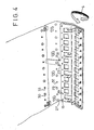
- Figures 3 to 6 show how the closure and sealing device 1 is mounted on an envelope 24 so that the latter becomes ready for use.
- mounting is initiated by fitting pins 5 and 14 into orifices 28 and 31 at the free end of flap 27 of the envelope. Maintaining device 1 in the same position, one begins to wrap the flap 27 of the envelope around the device.
- Figure 4 shows how the envelope has been passed down and backwardly in accordance with arrow S, tab 23 of device 1 being passed through its orifice 35 in flap 27.
- the two tongues 20 on part 2 of the device serve not only for securing device 1 to envelope 24, but also to define the ends of opening 26 of the envelope, holding them together and preventing tearing thereof.
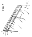
- flap 27 Since, as already mentioned, flap 27 is transparent, one can see therethrough the bases of pins 5 and their radial weakened connections 11, giving the impression of stars.
- the identifying pad 23 will be flush with the body of envelope 24 and should carry an identifying number or code.
- the envelope with the closure and sealing device as described above and illustrated in the attached drawings is extremely easy to use, and, at the same time, has a virtually 100% degree of tamper-proofness. It is impossible for an authorized third party wishing to tamper with the envelope to reach the locking locations of the multiple security seals represented by pins 5 and their female formations 15, and this is because the device 1 itself is totally wrapped in flap 27 of envelope 24, there not being any access except, possibly, to the first and last pins of the row. Any attempt to unlock a pin 5 from its end that fits into formation 15, is prevented due to the fact that the fitment is covered by the plastics material of flap 27 which would be cut or perforated by any attempt of this sort. Equally, any attempt to open device 1 would result in breaking the weakened connections 11 and this is easily visible through the transparent flap 27 (see Figure 7).
- flap 27 it is not essential that all of flap 27 be transparent, it being advisable that only the bases of pins 5 are visible, as shown in Figure 7.
- the whole flap may be transparent, a region thereof covering the bases of the pins (in the closed position) could be transparent, or the flap itself could be formed with a further series of orifices which would give direct access to the bases of pins 5.
- this last alternative is viable, it is advisable not to leave this free access to avoid any attempt to unlock the pins using thin needles.
Landscapes
- Engineering & Computer Science (AREA)
- Mechanical Engineering (AREA)
- Buffer Packaging (AREA)
- Lock And Its Accessories (AREA)
- Bag Frames (AREA)
Applications Claiming Priority (2)
| Application Number | Priority Date | Filing Date | Title |
|---|---|---|---|
| BR8706409A BR8706409A (pt) | 1987-11-26 | 1987-11-26 | Dispositivo para o fechamento e lacre de envelopes,envelope e envelope com dispositivo de fechamento e lacre |
| BR8706409 | 1987-11-26 |
Publications (2)
| Publication Number | Publication Date |
|---|---|
| EP0323706A2 true EP0323706A2 (fr) | 1989-07-12 |
| EP0323706A3 EP0323706A3 (fr) | 1989-08-23 |
Family
ID=4043671
Family Applications (1)
| Application Number | Title | Priority Date | Filing Date |
|---|---|---|---|
| EP88311175A Withdrawn EP0323706A3 (fr) | 1987-11-26 | 1988-11-25 | Dispositif pour la fermeture et le scellement d'enveloppes, enveloppe et enveloppe munie d'un dispositif de fermeture et de scellement |
Country Status (5)
| Country | Link |
|---|---|
| US (1) | US4983047A (fr) |
| EP (1) | EP0323706A3 (fr) |
| AU (1) | AU2581088A (fr) |
| BR (1) | BR8706409A (fr) |
| PT (1) | PT89071A (fr) |
Cited By (6)
| Publication number | Priority date | Publication date | Assignee | Title |
|---|---|---|---|---|
| WO1996022922A1 (fr) * | 1995-01-27 | 1996-08-01 | ELC Produtos de Segurança Indústria e Comércio Ltda. | Dispositif de fermeture et de scellement pour le scellement d'enveloppes, et enveloppe en matiere plastique le comportant |
| WO1996028359A1 (fr) * | 1995-03-10 | 1996-09-19 | ELC Produtos de Segurança Indústria e Comércio Ltda. | Liasse d'enveloppes de securite |
| WO1997029904A1 (fr) * | 1996-02-14 | 1997-08-21 | ELC Produtos de Segurança Indústria e Comércio Ltda. | Procede et dispositif pour appliquer des fermetures sur des enveloppes |
| WO2010066739A1 (fr) * | 2008-12-10 | 2010-06-17 | Wincor Nixdorf International Gmbh | Dispositif et procédé de fermeture d'au moins un contenant de transport d'objets de valeur, à parois fines, présentant au moins une ouverture |
| EP2204790A1 (fr) * | 2009-01-06 | 2010-07-07 | ID&C Limited | Dispositif de fixation anti-sabotage |
| US9129463B2 (en) | 2008-12-10 | 2015-09-08 | Wincor Nixdorf International Gmbh | Method for filling at least one thin-walled transport container with at least one valuable object and device for safekeeping at least one valuable object |
Families Citing this family (20)
| Publication number | Priority date | Publication date | Assignee | Title |
|---|---|---|---|---|
| US5042113A (en) * | 1990-10-02 | 1991-08-27 | Severson Sandra S | Elastic connector |
| US5797570A (en) * | 1991-02-15 | 1998-08-25 | Optical Coating Laboratory, Inc. | Portable device and method for mounting an anti-glare filter on a monitor |
| US5267643A (en) * | 1992-01-06 | 1993-12-07 | Scribner Richard C | Outdoor plastic information dispenser |
| BR9201123A (pt) * | 1992-03-31 | 1993-10-05 | Elc Prod Seguranca Ind | Dispositivo para o fechamento de malotes e semelhantes,bem como seio de seguranca |
| US5240105A (en) * | 1992-09-21 | 1993-08-31 | Allan Tsai | Multi-purpose eyeglasses pouch |
| EP0607475B1 (fr) * | 1993-01-15 | 1995-04-05 | Schmidt & Lenhardt GmbH & Co. oHG | Tube élévateur avec extrémités obturées par des baguettes pincées |
| US5524762A (en) * | 1994-12-29 | 1996-06-11 | Shafran; Barry W. | Disposable litter bag system |
| US5577395A (en) * | 1995-05-04 | 1996-11-26 | Scovill Fasteners Inc. | Clip for an identification bracelet |
| TW312105U (en) * | 1997-01-30 | 1997-08-01 | Yuan Sung Entpr Co Ltd | Belt buckle sling protector |
| DE20019536U1 (de) * | 2000-11-17 | 2002-03-21 | Rösler, Peter, 88239 Wangen | Aufhänger für Kunststofftaschen und -beutel |
| US6619479B2 (en) * | 2002-01-22 | 2003-09-16 | Adstracts, Inc. | Promotional bag dispensing apparatus |
| USD495369S1 (en) | 2003-11-12 | 2004-08-31 | Adstracts, Inc. | Clipboard |
| USD500082S1 (en) | 2003-11-12 | 2004-12-21 | Adstracts, Inc. | Clip |
| JP2008541884A (ja) * | 2005-05-26 | 2008-11-27 | レイノルズ コンシューマー プロダクツ、インク. | 不正開封表示封緘具付袋体 |
| US8196442B1 (en) * | 2010-02-24 | 2012-06-12 | The United States Of America As Represented By The Director, National Security Agency | Reusable tamper indicating bag closure |
| US8708302B2 (en) * | 2011-07-27 | 2014-04-29 | Stan G. Wilder | Wall calendar holder apparatus |
| BRPI1107001B1 (pt) * | 2011-11-29 | 2016-06-07 | Elc Produtos De Segurança Indústria E Comércio Ltda | sistema de lacre e selo de segurança incorporando o sistema de lacre |
| US20140263887A1 (en) * | 2013-03-13 | 2014-09-18 | Harry Miller Co., Inc. | Elevator pad hanging apparatus and method |
| US10392228B2 (en) | 2013-03-08 | 2019-08-27 | Harry Miller Co., Llc | Button hook pad hanger |
| US9873306B2 (en) * | 2014-11-17 | 2018-01-23 | Mahle International Gmbh | HVAC module with hinged clamp |
Family Cites Families (6)
| Publication number | Priority date | Publication date | Assignee | Title |
|---|---|---|---|---|
| US1155375A (en) * | 1912-08-06 | 1915-10-05 | James F Shannon | Grain-bag. |
| US2843309A (en) * | 1956-02-02 | 1958-07-15 | H J Dowd Co Inc | Tamper-proof shipping bag |
| US3727829A (en) * | 1971-02-19 | 1973-04-17 | Mazereu M | Closure device for plastic bags |
| DE2550135A1 (de) * | 1974-11-29 | 1976-08-12 | Itw Ltd | Satzsiegel |
| GB2171665B (en) * | 1985-02-28 | 1988-12-07 | Itw De France | Assemblies for use in the protection of bags |
| FR2590236B1 (fr) * | 1985-11-19 | 1988-01-15 | Sepal | Dispositif de fermeture inviolable pour sacs, en particulier pour sacs de transport de fonds |
-
1987
- 1987-11-26 BR BR8706409A patent/BR8706409A/pt unknown
-
1988
- 1988-11-23 AU AU25810/88A patent/AU2581088A/en not_active Abandoned
- 1988-11-24 PT PT89071A patent/PT89071A/pt not_active Application Discontinuation
- 1988-11-25 EP EP88311175A patent/EP0323706A3/fr not_active Withdrawn
-
1989
- 1989-10-30 US US07/429,124 patent/US4983047A/en not_active Expired - Lifetime
Cited By (8)
| Publication number | Priority date | Publication date | Assignee | Title |
|---|---|---|---|---|
| WO1996022922A1 (fr) * | 1995-01-27 | 1996-08-01 | ELC Produtos de Segurança Indústria e Comércio Ltda. | Dispositif de fermeture et de scellement pour le scellement d'enveloppes, et enveloppe en matiere plastique le comportant |
| US5924797A (en) * | 1995-01-27 | 1999-07-20 | Elc Produtos De Seguranca Industria E Comercio Ltda | Manually tearable closure seal device for envelopes |
| WO1996028359A1 (fr) * | 1995-03-10 | 1996-09-19 | ELC Produtos de Segurança Indústria e Comércio Ltda. | Liasse d'enveloppes de securite |
| WO1997029904A1 (fr) * | 1996-02-14 | 1997-08-21 | ELC Produtos de Segurança Indústria e Comércio Ltda. | Procede et dispositif pour appliquer des fermetures sur des enveloppes |
| WO2010066739A1 (fr) * | 2008-12-10 | 2010-06-17 | Wincor Nixdorf International Gmbh | Dispositif et procédé de fermeture d'au moins un contenant de transport d'objets de valeur, à parois fines, présentant au moins une ouverture |
| CN102308323B (zh) * | 2008-12-10 | 2015-01-07 | 德利多富国际有限责任公司 | 用于封闭至少一个存放有价值物品的具有至少一个开口的薄壁运送容器的装置和方法 |
| US9129463B2 (en) | 2008-12-10 | 2015-09-08 | Wincor Nixdorf International Gmbh | Method for filling at least one thin-walled transport container with at least one valuable object and device for safekeeping at least one valuable object |
| EP2204790A1 (fr) * | 2009-01-06 | 2010-07-07 | ID&C Limited | Dispositif de fixation anti-sabotage |
Also Published As
| Publication number | Publication date |
|---|---|
| EP0323706A3 (fr) | 1989-08-23 |
| PT89071A (pt) | 1989-09-14 |
| US4983047A (en) | 1991-01-08 |
| BR8706409A (pt) | 1989-06-13 |
| AU2581088A (en) | 1989-06-01 |
Similar Documents
| Publication | Publication Date | Title |
|---|---|---|
| EP0323706A2 (fr) | Dispositif pour la fermeture et le scellement d'enveloppes, enveloppe et enveloppe munie d'un dispositif de fermeture et de scellement | |
| US4733893A (en) | Transparent security seal | |
| US5123686A (en) | Tamper-proof bag seal | |
| US4106801A (en) | One piece security seal and new sealing system | |
| US4720040A (en) | Security deposit bag | |
| US5976014A (en) | Integrity seal form/label combination | |
| US4782977A (en) | Tamper resistant container | |
| US5667247A (en) | Telephone debit card production | |
| US4483018A (en) | High integrity tamper resistant container | |
| US4331237A (en) | Secure display clip | |
| US4424994A (en) | Security seals | |
| US8434673B2 (en) | Tamper evident enclosure for the storage and transport of documents | |
| EP1114408A1 (fr) | Sceau de securite code avec cache protecteur | |
| US5323908A (en) | System and apparatus for accurate drug inventory control | |
| CA2068565A1 (fr) | Dispositif d'etancheite inviolable pour bouteilles a gaz | |
| US3157421A (en) | Hasp seal | |
| EP0257978B1 (fr) | Fermeture de sécurité et poignée pour récipient | |
| US20180247571A1 (en) | Tamper-Evident Seal For Electricity Meters | |
| US3128114A (en) | Lock hasp seal | |
| US3094799A (en) | Identification tag | |
| US5600978A (en) | Device for the closure of bags or the like and security seal | |
| US5489034A (en) | Security seal for sealing the end of a tubular member | |
| US5924797A (en) | Manually tearable closure seal device for envelopes | |
| US783885A (en) | Bottle-seal. | |
| US2113306A (en) | Severable locking device |
Legal Events
| Date | Code | Title | Description |
|---|---|---|---|
| PUAI | Public reference made under article 153(3) epc to a published international application that has entered the european phase |
Free format text: ORIGINAL CODE: 0009012 |
|
| PUAL | Search report despatched |
Free format text: ORIGINAL CODE: 0009013 |
|
| AK | Designated contracting states |
Kind code of ref document: A2 Designated state(s): CH DE FR GB IT LI NL |
|
| AK | Designated contracting states |
Kind code of ref document: A3 Designated state(s): CH DE FR GB IT LI NL |
|
| STAA | Information on the status of an ep patent application or granted ep patent |
Free format text: STATUS: THE APPLICATION IS DEEMED TO BE WITHDRAWN |
|
| 18D | Application deemed to be withdrawn |
Effective date: 19900224 |