EP0323724B1 - Méthode de stabilisation d'hydro-isomérisats - Google Patents
Méthode de stabilisation d'hydro-isomérisats Download PDFInfo
- Publication number
- EP0323724B1 EP0323724B1 EP19880311988 EP88311988A EP0323724B1 EP 0323724 B1 EP0323724 B1 EP 0323724B1 EP 19880311988 EP19880311988 EP 19880311988 EP 88311988 A EP88311988 A EP 88311988A EP 0323724 B1 EP0323724 B1 EP 0323724B1
- Authority
- EP
- European Patent Office
- Prior art keywords
- catalyst
- oil
- wax
- liter
- alumina
- Prior art date
- Legal status (The legal status is an assumption and is not a legal conclusion. Google has not performed a legal analysis and makes no representation as to the accuracy of the status listed.)
- Expired
Links
Images

Classifications
-
- C—CHEMISTRY; METALLURGY
- C10—PETROLEUM, GAS OR COKE INDUSTRIES; TECHNICAL GASES CONTAINING CARBON MONOXIDE; FUELS; LUBRICANTS; PEAT
- C10G—CRACKING HYDROCARBON OILS; PRODUCTION OF LIQUID HYDROCARBON MIXTURES, e.g. BY DESTRUCTIVE HYDROGENATION, OLIGOMERISATION, POLYMERISATION; RECOVERY OF HYDROCARBON OILS FROM OIL-SHALE, OIL-SAND, OR GASES; REFINING MIXTURES MAINLY CONSISTING OF HYDROCARBONS; REFORMING OF NAPHTHA; MINERAL WAXES
- C10G65/00—Treatment of hydrocarbon oils by two or more hydrotreatment processes only
- C10G65/02—Treatment of hydrocarbon oils by two or more hydrotreatment processes only plural serial stages only
- C10G65/04—Treatment of hydrocarbon oils by two or more hydrotreatment processes only plural serial stages only including only refining steps
- C10G65/043—Treatment of hydrocarbon oils by two or more hydrotreatment processes only plural serial stages only including only refining steps at least one step being a change in the structural skeleton
Definitions
- the Group VIII metal component is preferably platinum.
- the catalysts of choice are selected from Group VIII on halogenated alumina or material containing alumina support, preferably alumina or material consisting predominantly (i.e.
- alumina catalyst preferably Group VIII on fluorided or chlorinated support, more preferably platinum on fluorided alumina support, most preferably platinum on fluorided ⁇ alumina catalyst.
- alumina catalyst preferably Group VIII on fluorided or chlorinated support, more preferably platinum on fluorided alumina support, most preferably platinum on fluorided ⁇ alumina catalyst.
- Slack wax containing from 0% to 25% oil coming from the dewaxing of conventional petroleum crude oils is subjected to hydrotreating over conventional hydrotreating catalyst so as to reduce the sulfur and nitrogen content levels of the wax.
- This hydrotreating is necessary so as to avoid deactivation of the typical Group VIII on halogenated refractory metal oxide isomerization catalyst.
- other, less sensitive isomerization catalyst, such as combination Group VI-Group VIII metal on refractory metal oxide catalysts are used, since such catalyst are usually sulfided prior to use, the need for prehydrotreating is lessened, if not eliminated.
- the feed from an isomerization unit utilizing such a catalyst would have to be treated to remove sulfur and/or nitrogen prior to being contacted with the Group VIII metal on refractory metal oxide or Group VIII metal on halogenated refractory metal oxide catalyst used in the present invention in the mild hydrorefining step following isomerization.
- the total liquid product of isomerized slack wax from the isomerization unit is then contacted with the Group VIII metal on refractory metal oxide catalyst or Group VIII on halogenated refractory metal oxide catalyst under mild hydrorefining conditions, which step is followed by a subsequent fractionation into various cuts boiling in the different lube basestock boiling ranges, dewaxing and final fractionation. While these steps can be practiced in different sequences it is preferred that the total liquid product from the isomerization unit be subjected to the herein described mild hydrorefining. It was unexpected that the mild hydrorefining can effectively treat this total liquid product since in the past it had been throught necessary to conduct such hydrofinishing procedures on fractions of oils and not on broad cuts of oils.
- fractionated isomerized wax products can be hydrofined it has also been unexpectedly discovered that unfractionated isomerized wax product, the total liquid product from the isomerization unit can be hydrorefined under mild conditions to produce a material of improved daylight stability.
- US-A-3979279 describes and claims a process for forming a stabilized lubricating oil resistant to oxidation and sludge formation upon exposure to a highly oxidative environment which comprises contacting a high boiling hydrocarbon fraction lubrication oil stock having a sulfur content above about 0.4 weight percent with hydrogen in the presence of a catalyst of low acidity having a chlorine content of less than about 1.5 weight percent comprised of from about 0.1 to about 10 weight percent metal selected from the the group consisting of platinum, palladium and a combination of thereof on a solid refractory inorganic oxide support, said contacting being at a temperature of about 400°F (204.4°C), a (gauge) pressure in the range of from about 150 psig (1.03MPa) to about 1200 psig (8.274MPa) and a weight hourly space velocity in the range of from about 0.1 to about 10.
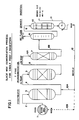
- Figure 1 is a schematic of an overall wax isomerization process utilizing a light slack wax feed and including the mild condition second stage hydrotreating of the present invention.
- Figure 2 is a schematic of an overall wax isomerization process utilizing a heavy micro-crystalline wax feed, including fractionator bottoms recycle and employing the mild condition second stage hydrotreating of the present invention.
- lube oil base stocks or blending stock oils made by the isomerization of slack waxes can have their daylight stability markedly improved by a process comprising contacting the total liquid product from the isomerization unit with a Group VIII metal on refractory metal oxide support catalyst or Group VIB-Group VIII metal on halogenated refractory metal oxide hydroisomerization catalyst under mild conditions.
- This mild condition hydrofinishing is performed at a temperature of from 170°C to 270°C, preferably 180 to 220°C, a flow velocity of 0.25 to 10 V/V/hr, preferably 1 to 4 V/V/hr, a pressure of from 300 to 1500 psi (2.069 to 10.343 MPa) H2, preferably 500 to 1000 psi (3.448 to 6.895 MPa) H2 and a hydrogen gas rate of 500 to 10,000 SCF/bbl (89.05 to 1780.94 liter gas/liter oil), preferably 1000 to 5000 SCF/bbl (178.09 to 890.47 liter gas/liter oil).
- Temperatures at the high end of the range should be employed only when similarly employing pressures at the high end of their recited range. Temperatures in excess of those recited may be employed if pressures in excess of 1500 psi (10.34 MPa) are used, but such pressures may not be practical or economic.
- any necessary hydrotreating of the slack wax feed is performed employing commercial catalyst, such as Co/Mo-Ni/Mo on alumina, under standard commercially accepted conditions, e.g., temperature of 320°C to 400°C, space velocity of 0.1 to 2.0 v/v/hr, pressure of from 500 to 3000 psig (3.448 to 20.685 MPa) H2, and gas rates of from 500 to 5000 SCF/B (89.05 to 890.47 liter gas/liter oil).
- commercial catalyst such as Co/Mo-Ni/Mo on alumina
- Isomerization is conducted over a catalyst containing a hydrogenating metal component typically one from Group VI or Group VIII or mixtures thereof, preferably Group VIII, more preferably noble Group VIII most preferably platinum on a halogenated refractory metal oxide support.
- the catalyst typically contains from 0.1-5.0 wt.% metal, preferably 0.1 to 1.0 wt.% metal, most preferably 0.2-0.6 wt.% metal.
- the refractory metal oxide support is typically a transition e.g. gamma or eta alumina and the halogen is most usually fluorine. Isomerization is accomplished under moderate to high temperature conditions of 270°C to 400°C, preferably 300°C to 360°C.
- Space velocity ranges from 0.10 to 10 v/v/hr, preferably 1.0 to 2.0 v/v/hr.
- Pressure ranges from 500 to 3000 psi (3.448 to 20.685 MPa) H2, preferably 1000 to 1500 psi (6.895 to 10.343 MPa) H2.
- Hydrogen gas rate ranges from 1000 to 10,000 SCF/B (178.09 to 1780.94 liter gas/liter oil). Moderate levels of conversion of wax to isomerate are preferred. Conversions to a level such that about 40% or less unconverted wax remains in the 370°C+ fraction sent to the dewaxer, preferably 15-35% unconverted wax remains in the 370°C+ fraction sent to the dewaxer are preferred.
- the prehydrotreating step can be dispensed with, but the isomerized wax product would still have to be freed of H2S and NH3 prior to being contacted with the second stage catalyst. This could be done by flashing or stripping of the product to remove H2S and NH3.
- a preferred catalyst for use in the present process contains a hydrogenation metal component which is a Group VIII noble metal or mixture thereof, preferably noble Group VIII metal, most preferably platinum on a fluorided alumina or material containing alumina, preferably alumina or material consisting predominantly (i.e.
- XRD X-ray diffraction
- the fluoride content of the catalyst can be determined in a number of ways.
- Fluoride concentration of the sample is determined by ion chromatography analysis of the combustion product solution. Calibration curves are prepared by combusting several concentrations of ethanolic KF standards (in the same manner as the sample) to obtain a 0-10 ppm calibration range. Fluoride concentration of the catalyst is calculated on an ignition-loss-free-basis by comparison of the sample solution response to that of the calibration curve. Ignition loss is determined on a separate sample heated to 800 degrees F (426.7°C) for at least 2 hours. Ion chromatographic analysis uses standard anion conditions.
- Fluoride distillation with a titrimetric finish. Fluorides are converted into fluorosilicic acid (H2SiF6) by reaction with quartz in phosphoric acid medium, and distilled as such using super heated steam. This is the Willard-Winter-Tananaev distillation. It should be noted that the use of super heated, dry (rather than wet) steam is crucial in obtaining accurate results. Using a wet steam generator yielded results 10-20% lower. The collected fluorosilicic acid is titrated with standardized sodium hydroxide solution. A correction has to be made for the phosphoric acid which is also transferred by the steam. Fluoride data are reported on an ignition-loss-free-basis after determination of ignition loss on a sample heated to 400 degree C for 1 hour.
- Another preferred catalyst is a catalyst prepared by a process involving depositing a hydrogenation metal on an alumina or material containing alumina support, calcining said metal loaded support typically at between 350 to 500°C, preferably 450 to 500°C for 1 to 5 hours, preferably 1 to 3 hours and fluoriding said metal loaded support using a high pH fluorine source solution to a bulk fluorine level of about 8 wt% or less (e.g., 2 to 8 wt%), preferably about 7 wt% or less, said high pH source solution being at a pH of 3.5 to 4.5 and preferably being a mixture of NH4H and HF followed by rapid drying/heating in a thin bed or rotary kiln to insure thorough heating in air, an oxygen containing atmosphere or an inert atmosphere to a temperature between 350 to 450°C in about 3 hours or less, preferably 375 to 400°C, and holding at the final temperature, if necessary, for a time sufficient to reduce the hydrate content to the a
- a low pH fluorine source solution having a pH of less than 3.5
- aqueous solutions of HF or appropriate mixtures of HF and NH4F to a bulk fluorine level of about 10 wt% or less (e.g., 2 to 10 wt%), preferably about 8 wt% or less
- drying/heating in a thin bed or rotary kiln to a temperature of 350 to 450°C, preferably 375 to 425°C in air an oxygen containing atmosphere, or an inert atmosphere and holding for 1 to 5 hours.
- the alumina or alumina containing support material is preferably in the form of extrudates, and are preferably at least about 1/32 inch (0.7938 mm) across the longest cross-sectional dimension. If the low pH prepared catalyst is first charged to a unit, the catalyst must be held at the final activation temperature for longer than 5 hours, preferably longer than 10 hours and preferably at temperatures of 400 to 450°C.
- the above catalysts typically contain from 0.1 to 5.0 wt% metal, preferably 0.1 to 1.0 wt% metal, most preferably 0.2 to 0.6 wt% metal.
- the dried/heated catalyst has a surface nitrogen content N/Al of 0.01 or less by X-ray photoelectron spectroscopy (XPS, preferably an N/Al of 0.007 or less, most preferably an N/Al of 0.004 or less by XPS.
- XPS X-ray photoelectron spectroscopy
- the catalyst following the above recited heating step can be charged to the isomerization reactor and brought quickly up to operating conditions.
- the catalyst prepared using the pH 3.5 to 4.5 solution technique can be activated, preferably in pure or plant hydrogen (60 to 70% H2) at 350 to 450°C, care being taken to employ short activation times, from 1 to 24 hours, preferably 2 to 10 hours being sufficient. Long activation times (in excess of 24 hours) have been found to be detrimental to catalyst performance.
- catalysts made using solutions of pH less than 3.5 can be activated in pure or plant hydrogen at 350 to 500°C for from 1 to 48 hours or longer.
- catalyst prepared using solutions of pH less than 3.5 are not heated first, then it is preferred that they be subsequently activated at more severe conditions, i.e. for longer times and/or at higher temperatures. On the other hand, if they are heated first, then moderate activation condition procedures similar to those employed with catalysts made from higher pH solution techniques will suffice.
- a typical activation profile shows a profile of 2 hours to go from room temperature with 100°C with the catalyst being held at 100°C for 0 to 2 hours then the temperature is raised from 100 to 350 over a period of 1 to 3 hours with a hold at the final temperature of from 1 to 4 hours.
- the catalyst can be activated by heating from room temperature to the final temperature of 350 to 450°C over a period of 2 to 7 hours with a hold at the final temperature of 0 to 4 hours. Similar activation can be accomplished by going from room temperature to the final temperature of 350 to 450°C in 1 hour.
- Another preferred catalyst comprises a hydrogenating metal on fluorided alumina or material containing alumina support made by depositing the hydrogenation metal on the support and fluoriding said metal loaded support using acidic fluorine sources such as HF by any convenient technique such as spraying, soaking, incipient wetness, etc. to deposit between 2-10% F preferably 2-8% F.
- acidic fluorine sources such as HF
- the catalyst is dried, typically at 120°C and then crushed to expose inner surfaces, the crushed catalyst is double sieved to remove fines and uncrushed particles.
- This sized catalyst is 1/32 inch (0.7938 mm) or less and typically from 1/64 to 1/32 inch (0.3969 to 0.7938 mm) in size across its largest cross-sectional dimension.
- the starting particle or extrudate may be of any physical configuration. Thus, particles such as cylinders, trilobes or quadrilobes may be used. Extrudates of any diameter may be utilized and can be anywhere from 1/32 of an inch (0.7938 mm) to many inches (or mm) in length, the length dimension being set solely by handling considerations. It is preferred that following sizing the particle have a length smaller than the initial extrudate diameter.
- the particle or extrudate is crushed or fractured to expose inner surfaces.
- the crushing is conducted to an extent appropriate to the particle or extrudate with which one is starting.
- an extrudate which is 1 foot (30.48 cm) long and 1/16 inch (1.5875 mm) in diameter would be sized into pieces which range anywhere from 1/64 to 1/32 inch (0.3969 to 0.7938 mm) across its longest cross-sectional dimension.
- the extrudate is only 1/16 inch (1.5875 mm) to begin with it will be enough simply to break it in half, into two 1/32 inch (0.7938 mm) pieces, for example.
- metal loaded support particle which is already about 1/32 inch (0.7938 mm) in size or smaller and fluoride it as described above using HF.
- the sized material will range in size between 1/64 to 1/32 inch (0.3969 to 0.7938 mm) in size.
- the uncalcined catalyst is activated in a hydrogen atmosphere such as pure hydrogen or plant hydrogen containing 60 to 70 vol% H2 by heating to 350 to 500°C, preferably 350 to 450°C for from 1 to 48 hours or longer.
- a hydrogen atmosphere such as pure hydrogen or plant hydrogen containing 60 to 70 vol% H2 by heating to 350 to 500°C, preferably 350 to 450°C for from 1 to 48 hours or longer.
- the hydrogen activation profiles previously described may be used here.
- This sized catalyst is unexpectedly superior for wax isomerization as compared to the uncrushed particle or extrudate starting material. It has also been discovered that 370°C+ oil products made using the sized catalyst as compared to the uncrushed or extrudate material starting with wax possessing about 5 to 10% oil exhibit higher VI's than 370+°C oil products made starting with wax possessing 0% oil (on the one hand) and about 20% oil (on the other). Therefore, to produce products having the highest VI one would isomerize wax having from 5 to 15% oil, preferably 7 to 10% oil using the "sized" catalyst produced using HF.
- One desiring to maximize the production of lube oil having a viscosity in the 5.6 to 5.9 cSt/100°C range should practice the isomerization process under low hydrogen treat gas rate conditions, treat gas rates on the order of 500 to 5000 SCF/bbl H2 (89.05 to 890.47 liter gas/liter oil), preferably 2000 to 4000 SCF/bbl, H2 (356.19 to 712.38 liter gas/liter oil), most preferably about 2000 to 3000 SCF/bbl, H2 (356.19 to 534.28 liter gas/liter oil).
- the isomerized wax material is then subjected to second stage catalyst using a Group VIII metal on refractory metal oxide catalyst or Group VIII metal on halogenated refractory metal oxide catalyst.
- the halogenated catalyst can be the same or different than the Group VIII metal on halogenated refractory metal oxide catalyst used in the prior isomerization reactor. If the same catalyst is used, the process can be run in blocked sequence,, the reactor first used to produce isomerate by being run at severe conditions with the isomerate going to tankage, the stored isomerate being subsequently recycled through the unit now run under mild conditions to remove trace quantities of polynuclear aromatics and other constituents detrimental to daylight and oxidation stability, but which conditions are not sufficient to effect further isomerization of the hydrocarbon components.
- This second stage zone is run at a temperature of 170°C to 270°C, preferably 180°C to 220°C, a flow velocity of 0.25 to 10 v/v/hr, preferably 1 to 4 v/v/hr, a pressure of from 300 to 1500 psi (2.068 to 10.342 MPa) H2, preferably 500 to 1000 psi H2 (3.448 to 6.895 MPa), and a hydrogen gas rate of 500 to 10,000 SCF/B (89.05 to 1780.94 liter gas/liter oil), preferably 1000 to 5000 SCF/B (178.09 to 890.47 liter gas/liter oil). Higher temperatures may be employed if pressures in excess of 1500 psi are used, but such high pressures may not be practical.
- the isomerate is fractionated into a lubes cut and fuels cut, the lubes cut being identified as that fraction boiling in the 330°C+ range, preferably the 370°C+ range and even higher.
- This lubes fraction is then dewaxed to a pour point of about -21°C or lower. Dewaxing is accomplished by techniques which permit the recovery of unconverted wax, since in the process of the present invention this unconverted wax is recycled to the isomerization unit. It is preferred that this recycle wax be recycled to the main wax reservoir and be passed through the hydrotreating unit to remove any quantities of entrained dewaxing solvent which solvent could be detrimental to the isomerization catalyst.
- Solvent dewaxing is utilized and employs typical dewaxing solvents.
- Solvent dewaxing utilizes typical dewaxing solvents such as C3-C6 ketones (e.g. methyl ethyl ketone, methyl isobutyl ketone and mixtures thereof), C6-C10 aromatic hydrocarbons (e.g. toluene), mixtures of ketones and aromatics (e.g.
- MEK/toluene autorefrigerative solvents such as liquefied, normally gaseous C2-C4 hydrocarbons such as propane, propylene, butane, butylene and mixtures thereof, etc. at filter temperature of -25 to -30°C.
- the preferred solvent to dewax the isomerate, especially isomerates derived from heavier waxes (e.g. Bright Stock Waxes) under miscible conditions and thereby produce the highest yield of dewaxed oil at a high filter rate is a mixture of MEK/MIBK (20/80 v/v) used at a temperature in the range -25 to -30°C.
- the fractionation bottoms are recycled by being sent first to the fresh feed reservoir and combined with the wax therein.
- the isomerate from the second stage catalyst zone can be fractionated into narrow cuts and each cut individually dewaxed.
- Figures 1 and 2 present schematic representations of preferred embodiments of the wax isomerization process.
- slack wax feed derived from for example a lighter oil such as 600N oil or lighter is fed from the reservoir (1) to a hydrotreater (3) via line 2 wherein heteroatom compounds are removed from the wax.
- This hydrogenated slack wax is then fed via line 4 to the isomerization unit (5) after which the total liquid product is fed first via lines 6 and 6A to a low temperature, mild condition second stage treating unit (unit 7) wherein the TLP is contacted with the isomerization catalyst or simply a noble Group VIII metal on aluminum catalyst to produce a stream which is then sent via line 6B to the fractionator tower (unit 8).
- the tube stream boiling in the 370°C+ range is then forwarded via line 9 to the solvent dewaxer (unit 10) for the separation of waxy constituents therefrom, the dewaxed oil fraction being recovered via line 11 and forwarded to other conventional treatment processes normally employed on base stock or blending stock oils.
- the recovered wax is recycled either directly to the slack wax stream being fed to the isomerization unit or it is recycled to the wax reservoir (1) via line 12B for passage through the hydrotreater prior to being recycled to the isomerization unit.
- Figure 2 the wax processing stream is much like that of Figure 1, the main difference being that Figure 2 represents the scheme for handling heavier slack wax feeds, such as a wax feed derived from Bright Stock oil
- the wax from reservoir 1 is fed via line 2 to the hydrotreater (3) prior to being sent via line 4 to the isomerization unit (unit 5) after which it is fed via lines 6 and 6A to a low temperature mild condition second stage treating unit (unit 7) wherein it is contacted with a further charge of isomerization catalyst or simply noble Group VIII metal on alumina and fed via line 6B to the fractionator tower (unit 8).
- the isomerate made using the heavy wax is fractionated into a light fraction boiling in the 370°C- (a fuels cut) a lube cut boiling in the 370°C+ range and a bottoms fraction boiling in the 580°C+ range.
- the lubes fraction, a broad cut boiling in the 370°C to 580°C range is sent via line 9 to the dewaxer (unit 10) as previously described.
- the 580°C+ bottoms fraction contains appreciable wax and is recycled via lines 13, 13A, 13B and 4 to the isomerization unit (5).
- This bottoms fraction optionally can be combined via lines 13 and 13C with the wax in line 12 recovered from the dewaxing unit (10) in which case the total recycled stream can be fed directly to the isomerization unit via lines 12A, 13B and 4 or it can be sent to the wax reservoir (1) via line 12B for treatment of the hydrotreater prior to being fed to the isomerization unit.
- the following catalysts were used either as first stage isomerization catalyst and/or as second stage mild condition hydrofinishing catalyst. Which catalyst was used in what service is identified in each example.
- raw slack waxes from the dewaxing of petroleum oils were hydrotreated to remove polar materials, as well as heteroatomic compounds (sulfur and nitrogen containing compounds) which would deactivate the platinum on fluorided alumina hydroisomerization catalysts.
- Any conventional hydrotreating catalyst can be used, e.g., Cyanamid's HDN-30; Katalco's NM-506; Ketjen's KF-840; etc.
- the prime processing targets for the hydrotreated material are a sulfur content of about 10 ppm or less and a nitrogen content of 1 ppm or less.
- Ketjen KF-840 was used in the form of 1/20 inch (1.27 mm) quadrilobes.
- the catalyst as received from the manufacturer, had 4% NiO and 19.5% MoO3 on an alumina base, and had a surface area of 180 m2/gram, with an average pore volume of 0.35 cm3/g, and an average pore radius of 38 ⁇ (3.8 nm). Twelve liters of this catalyst was packed into a tubular fixed bed 189 cm long and 9.9 cm in diameter and sulfided by exposure to H2S in hydrogen and a sulfur containing vacuum distillate. The hydrotreating unit can be run in either up-flow or down-flow mode. Two different slack waxes were hydrotreated, a Western Canadian 600N slack wax, and an Augusta Bright Stock slack wax. Typical properties of each feed are given below in Table 1.
- the 600N slack wax was hydrotreated in an up-flow mode at 0.5 v/v/hr, 1000 psig (6.895 MPa) hydrogen pressure and a gas treat rate of 1500 SCF H2/B (267.14 liter gas/liter oil).
- reaction temperature was held at 320°C and thereafter at 330°C.
- the slick wax sulphur contents ranged from 0.073 weight percent to 0.113 weight percent and nitrogen content ranged from 12 to 17 wppm.
- Periodic analysis of the hydrotreated wax showed that sulphur contents were consistently 4 wppm and lower, while nitrogen contents were always 2 wppm or less.
- the Bright Stock slack waxes feeds having different oil contents were hydrotreated in an up-flow mode at 380°C, 1000 psig (6.895 MPa) hydrogen pressure and 1500 SCFH2/B (267.14 liter gas/liter oil) treat gas rate.
- the space velocity was varied from 0.42 to 0.5, in order to obtain the desired sulfur and nitrogen reduction. Inspections of the hydrotreated wax feeds used in the examples are given below in Table 2.
- Base oils were prepared from the total liquid product coming from the isomerization zone by fractionating said TLP into various lube fractions and dewaxing said lube fraction to a pour point of -21°C.
- daylight stability was determined on the products from 1 through 5 (above) by exposing 5 ml samples in the presence of air continuously in a light box apparatus in which the lamp used was an Excella fluorescent tube from Sunburst Electric which simulated the intensity and frequency range of actual solar radiation. Samples were rated daily on the degree of haze, floc and sludge formation as to time exposed to air and radiation.
- the dewaxed base stock oils above 1-5 were evaluated for daylight stability and found to exhibit the following: TABLE 3 Dewaxed Base Oil # Daylight Stability 1 Light haze, 48 hrs; distinct haze 96 hrs. 2 Haze/sludge ⁇ 24 hours 3 Haze/sludge ⁇ 24 hours 4 Haze/sludge ⁇ 24 hours 5 Haze/sludge ⁇ 24 hours It is seen that none of these dewaxed isomerate base oil products exhibit acceptable daylight stability since conventional lube base oils normally have daylight stability in excess of 10 days.
- Base oils 3 and 4 were hydrofinished over sulfided KF-840 (Ni-Mo/Al2O3) at 300°C at 500 psi (3.447 MPa), 500 SCF H2/bbl (89.05 liter H2 gas/liter oil) and 1 v/v/hr. These hydrofinished base oils were evaluated for daylight stability and found to exhibit the following somewhat improved but still unacceptable daylight stabilities: TABLE 4 KF-840 Hydrofined Dewaxed Base Oil Daylight Stability 3 Haze/sludge, 50 hours 4 Haze/sludge, 100 hours
- Dewaxed base oils 3, 4 and 5 were hydrofinished over Pt/F-Al2O3 Catalyst B under a number of conditions (recited in Table 4).
- the hydrofinished base oils were evaluated for daylight stability and found to exhibit the following: When dealing with isomerate fractions, it is seen that hydrofinishing under higher treat gas rates gave a product of improved stability.
- the hydrofinished material was fractionated to obtain the 370°C+ fraction for subsequent dewaxing to -21°C pour using 100% MIBK solvent at a 4/1 solvent to oil dilution ratio and -26°C filter temperature. This dewaxed oil fraction was evaluated for daylight stability.
- the 600N slack wax isomerate (TLP), feed D and Bright Stock slack wax isomerate (TLP) feed B were hydrofinished over Pt/alumina, catalyst E (previously described), under the conditions recited below.
- the hydrofinished materials were fractioned into 370°C+ fraction and dewaxed to -20°C pour as recited in Example 4.
- the dewaxed fraction were evaluated for daylight stability (Table 7). It is seen that hydrofinishing a total liquid product over a platinum on alumina catalyst produces a material having improved daylight stability as compared to materials derived from TLP's hydrofinished over conventional hydrofinishing catalysts.
- the hydrofinished isomerate was fractionated to obtain the 370°C+ fraction for solvent dewaxing to -21°C pour using 100% MIBK solvent at 4/1 solvent to oil dilution ratio and -26°C filter temperatures to dewax as recited in Example 4.
- the dewaxed fraction was evaluated for daylight stability (Table 8).
- the hydrofinished isomerate was fractioned to obtain the 370°C+ fraction for segment dewaxing to -21°C pour using 100% MIBK solvent at 4/1 solvent to oil dilution ratio and -26°C filter temperature to dewax as recited in Example 4.
- the dewaxed fraction was evaluated for daylight stability (Table 9).
- Bright Stock slack wax isomerate (TLP), feed (a) was hydrofinished over Pt/F-Al2O3, Catalyst B, conditions recited below.
- the unhydrofinished TLP and the hydrofinished materials were vacuum distilled to produce 460 to 550°C fractions, then dewaxed. These fractions were dewaxed with 5% toluene/95% MIBK at a solvent oil ratio of 4:1 and a filter temperature of -27°C.
- Each dewaxed fraction was then evaluated for daylight stability. From this it is seen that hydrofinishing at a temperature lower than about 270°C is preferred for producing daylight stable base oil products from TLP's.
- the hydrofinished materials were vacuum distilled to produce heart-cut fractions boiling in the 370°C to 580°C range. These fractions were dewaxed with 100% MIBK using a solvent:oil ratio of 4:1 and a filter temperature of -30°C.
- the dewaxed heart-cut fractions were then further fractionated into light (4.5 cSt) and heavy (8.4 cSt) dewaxed oil fractions as shown in Table 11 and evaluated for daylight stability.
- hydrofinishing the total liquid products coming from the isomerization unit using the Group VIII metal on refractory metal oxide or Group VIII metal on halogenated refractory metal oxide catalyst produce dewaxed base oils which exhibit superior daylight stability as compared to the unhydrofinished dewaxed base oils and dewaxed base oils hydrofinished using conventional hydrofinishing catalyst.
- the examples show that hydrofinishing must be performed within a narrow window of temperature conditions, i.e. about 170-270°C, preferably 180-220°C when operating under consistent mild pressure, treat gas rate and flow velocity conditions.
- a hydrocracked lube basestock was prepared as follows: Recycle from a fuels hydrocracker was withdrawn with the hydrocracker operating at the following conditions: Feed Heavy Coker Gas Oil Fresh Feed Rate, kB/Day 11.2 Conversion, Wt.% 90.6 Recycle Withdrawal, kB/Day 1.05 Reactor 1 temperature, °C 401.6 Reactor 2 temperature, °C 376.5 Total Pressure,(psi) MPa (2100) 14.48
- the lube distillate was solvent dewaxed using a 40/60 mixture of MEK/MIBK, solvent to oil ratio of 2/1, and a filter temperature of -22°C.
- the resulting dewaxed oil had the following properties: Viscosity at 40°C cSt 13.44 Viscosity Index 109 Saturates, Wt.% 96.0
- This basestock has excellent viscometric properties.
- a sample of this basestock was hydrofinished over a conventional sulphided Ni/Mo on Al2O3 catalyst (KF-840) at 300°C, 2.0 LHSV, 350 psi (2.413 MPa) H2, 500 SCF/B, H2, (89.05 liter H2 gas/liter feed) treat gas rate.
- a similar sample of fractionated hydrocrackate was hydrofinished according to the invention over a Pt/F/Al2O3 catalyst (Catalyst B) at 200°C, 1.0 LHSV, 1000 psi (6.895 MPa) H2 and 5000 SCF/bbl (890.47 liter gas/liter feed) treat gas rate.
Landscapes
- Chemical & Material Sciences (AREA)
- Oil, Petroleum & Natural Gas (AREA)
- Engineering & Computer Science (AREA)
- Chemical Kinetics & Catalysis (AREA)
- General Chemical & Material Sciences (AREA)
- Organic Chemistry (AREA)
- Production Of Liquid Hydrocarbon Mixture For Refining Petroleum (AREA)
- Catalysts (AREA)
- Lubricants (AREA)
- Fats And Perfumes (AREA)
Claims (6)
- Procédé pour améliorer la stabilité à la lumière du jour d'une huile de base lubrifiante ou d'une huile mélangée de base produite par isomérisation de paraffine, ledit procédé comprenant l'hydroraffinage (a) du produit liquide total produit dans l'unité d'isomérisation de la paraffine, ou bien (b) de la fraction de domaine d'ébullition lubrifiant de l'isomérisat, ledit hydroraffinage employant un catalyseur choisi parmi un métal du groupe VIII sur un oxyde métallique réfractaire et un métal du groupe VIII sur un oxyde métallique réfractaire halogéné, une température dans la gamme de 170 à 270°C, une vitesse d'écoulement de 0,25 à 10 v/v/h, une pression de 300 à 1500 psi (2,069 à 10,343 MPa) de H₂ et un débit d'hydrogène gazeux de 500 à 10 000 SCF/B (89,05 à 1780,94 litres de gaz/litre d'huile).
- Procédé selon la revendication 1, dans lequel le produit liquide total hydroraffiné est fractionné pour donner une fraction d'huile lubrifiante et le déparaffinage de ladite fraction d'huile lubrifiante.
- Procédé selon la revendication 1 ou la revendication 2, dans lequel l'étape d'hydroraffinage est effectuée à une température dans la gamme de 180 à 220°C, à une vitesse d'écoulement de 1 à 4 v/v/h, sous une pression de 500 à 1000 psi (3,448 à 6,895 MPa) de H₂ et à un débit d'hydrogène gazeux de 1 000 à 5 000 SCF/B (178,09 à 890,47 litres de gaz/litre d'huile).
- Procédé selon l'une quelconque des revendications 1 à 3, dans lequel le catalyseur utilisé dans l'étape d'hydroraffinage est le platine ou le palladium sur un oxyde métallique réfractaire ou le platine ou le palladium sur un oxyde métallique réfractaire halogéné.
- Procédé selon l'une quelconque des revendications 1 à 4, dans lequel le catalyseur utilisé dans l'étape d'hydroraffinage modérée est le platine ou le palladium sur de la silice, de la silice/alumine ou de l'alumine fluorées ou chlorées.
- Procédé selon l'une quelconque des revendications 1 à 5, dans lequel le catalyseur est le platine sur de l'alumine de transition fluorée.
Applications Claiming Priority (2)
| Application Number | Priority Date | Filing Date | Title |
|---|---|---|---|
| US13514987A | 1987-12-18 | 1987-12-18 | |
| US135149 | 1993-10-12 |
Publications (3)
| Publication Number | Publication Date |
|---|---|
| EP0323724A2 EP0323724A2 (fr) | 1989-07-12 |
| EP0323724A3 EP0323724A3 (en) | 1990-03-28 |
| EP0323724B1 true EP0323724B1 (fr) | 1992-09-09 |
Family
ID=22466772
Family Applications (1)
| Application Number | Title | Priority Date | Filing Date |
|---|---|---|---|
| EP19880311988 Expired EP0323724B1 (fr) | 1987-12-18 | 1988-12-16 | Méthode de stabilisation d'hydro-isomérisats |
Country Status (7)
| Country | Link |
|---|---|
| EP (1) | EP0323724B1 (fr) |
| JP (1) | JP2711120B2 (fr) |
| AU (1) | AU609553B2 (fr) |
| CA (1) | CA1328635C (fr) |
| DE (1) | DE3874510T2 (fr) |
| ES (1) | ES2034274T3 (fr) |
| MX (1) | MX169942B (fr) |
Families Citing this family (10)
| Publication number | Priority date | Publication date | Assignee | Title |
|---|---|---|---|---|
| CA2047923C (fr) * | 1990-08-14 | 2002-11-19 | Heather A. Boucher | Hydrotraitement de residus lourds d'hydro-isomerisation de colonne de distillation visant a produire apres refractionnement une huile legere de qualite |
| US5453176A (en) * | 1993-10-13 | 1995-09-26 | Narloch; Bruce A. | Process for preparing white oil containing a high proportion of isoparaffins |
| US5565086A (en) * | 1994-11-01 | 1996-10-15 | Exxon Research And Engineering Company | Catalyst combination for improved wax isomerization |
| BR9602049A (pt) * | 1995-04-28 | 1998-10-06 | Shell Int Research | Processo para a produção de óleos base lubrificantes |
| EP0744452B1 (fr) * | 1995-04-28 | 1999-12-29 | Shell Internationale Researchmaatschappij B.V. | Procédé de production d'huiles de base pour lubrifiants |
| EP0743351B1 (fr) * | 1995-05-19 | 2000-08-09 | Shell Internationale Researchmaatschappij B.V. | Procédé de préparation d'huiles de base lubrificante |
| US7132042B2 (en) * | 2002-10-08 | 2006-11-07 | Exxonmobil Research And Engineering Company | Production of fuels and lube oils from fischer-tropsch wax |
| WO2013147305A1 (fr) * | 2012-03-30 | 2013-10-03 | Jx日鉱日石エネルギー株式会社 | Huile de base de lubrifiant et son procédé de production |
| WO2013147302A1 (fr) * | 2012-03-30 | 2013-10-03 | Jx日鉱日石エネルギー株式会社 | Huile de base pour lubrifiant et son procédé de fabrication |
| CN112601804B (zh) * | 2018-09-07 | 2023-01-13 | 引能仕株式会社 | 蜡的制造方法、蜡、润滑油基础油的制造方法 |
Family Cites Families (5)
| Publication number | Priority date | Publication date | Assignee | Title |
|---|---|---|---|---|
| CA1069452A (fr) * | 1974-04-11 | 1980-01-08 | Atlantic Richfield Company | Production d'huiles blanches par hydrogenation a deux etapes |
| US3979279A (en) * | 1974-06-17 | 1976-09-07 | Mobil Oil Corporation | Treatment of lube stock for improvement of oxidative stability |
| FR2320775A1 (fr) * | 1975-08-13 | 1977-03-11 | Raffinage Cie Francaise | Catalyseurs d'isomerisation d'hydrocarbures, procede de preparation et application desdits catalyseurs |
| JPS5242506A (en) * | 1975-10-02 | 1977-04-02 | Toa Nenryo Kogyo Kk | Hydrotreating process of petroleum wax |
| JPS5397006A (en) * | 1977-02-04 | 1978-08-24 | Labofina Sa | Production of heavy paraffins free from aromatic components |
-
1988
- 1988-12-16 ES ES88311988T patent/ES2034274T3/es not_active Expired - Lifetime
- 1988-12-16 EP EP19880311988 patent/EP0323724B1/fr not_active Expired
- 1988-12-16 DE DE19883874510 patent/DE3874510T2/de not_active Expired - Fee Related
- 1988-12-16 AU AU26941/88A patent/AU609553B2/en not_active Ceased
- 1988-12-16 CA CA000586216A patent/CA1328635C/fr not_active Expired - Fee Related
- 1988-12-16 MX MX1423088A patent/MX169942B/es unknown
- 1988-12-19 JP JP63320312A patent/JP2711120B2/ja not_active Expired - Fee Related
Also Published As
| Publication number | Publication date |
|---|---|
| AU609553B2 (en) | 1991-05-02 |
| ES2034274T3 (es) | 1993-04-01 |
| JP2711120B2 (ja) | 1998-02-10 |
| JPH02263896A (ja) | 1990-10-26 |
| MX169942B (es) | 1993-08-02 |
| AU2694188A (en) | 1989-06-22 |
| EP0323724A2 (fr) | 1989-07-12 |
| CA1328635C (fr) | 1994-04-19 |
| DE3874510T2 (de) | 1993-03-18 |
| DE3874510D1 (de) | 1992-10-15 |
| EP0323724A3 (en) | 1990-03-28 |
Similar Documents
| Publication | Publication Date | Title |
|---|---|---|
| US5158671A (en) | Method for stabilizing hydroisomerates | |
| US5059299A (en) | Method for isomerizing wax to lube base oils | |
| US6884339B2 (en) | Flexible method for producing oil bases with a ZSM-48 zeolite | |
| EP0323092B1 (fr) | Procédé d'hydro-isomérisation de la cire de Fischer-Tropsch en vue de la production d'une huile lubrifiante | |
| US4919786A (en) | Process for the hydroisomerization of was to produce middle distillate products (OP-3403) | |
| EP0585358B1 (fr) | Isomerisation catalytique de cire avec un catalyseur d'isomerisation a porosite et a aire de surface elevees | |
| US6103101A (en) | Process for producing lube base oils of high viscosity index and diesel oil of high cetaned number | |
| US4992159A (en) | Upgrading waxy distillates and raffinates by the process of hydrotreating and hydroisomerization | |
| KR100695180B1 (ko) | 전환-수소화 이성화 반응후 접촉 탈왁스화 처리에 의한베이스 오일 및 중간 증류물의 융통적인 제조 방법 | |
| EP0321307B1 (fr) | Méthode d'isomérisation de cires en huiles lubrifiantes de base | |
| HUP0004280A2 (hu) | Rétegezett katalizátorrendszer alapolaj hidrokonverziójára | |
| US5370788A (en) | Wax conversion process | |
| AU609552B2 (en) | Method for isomerizing wax to lube base oils using an isomerization catalyst | |
| EP0471524B1 (fr) | Procédé d'hydrotraitement d'un produit de queue d'un fractionnement d'un hydroisomérisat en vue de la production d'une huile légère de haute qualité après un refractionnement consécutif | |
| AU612214B2 (en) | Improved yields of 5.6-5.9 cst/100degrees c oil by wax isomerization employing low treat gas rates | |
| EP0323724B1 (fr) | Méthode de stabilisation d'hydro-isomérisats | |
| US4959337A (en) | Wax isomerization catalyst and method for its production | |
| JP2022545642A (ja) | 基油収率を改善するためのプロセス | |
| US20220143587A1 (en) | High nanopore volume catalyst and process using ssz-91 | |
| EP0431448B1 (fr) | Procédé catalytique de préparation d'huiles lubrifiantes à bas point d'écoulement | |
| US12544737B2 (en) | High nanopore volume hydrotreating catalyst and process | |
| EP0321298A2 (fr) | Méthode d'isomérisation de cire en huiles lubrifiantes de base en appliquant un catalyseur d'isomérisation de dimension déterminée | |
| EP0321306A2 (fr) | Procédé d'isomérisation en cire à l'aide d'un catalyseur à palladium sur de l'aluminium fluorée | |
| EP0321299A2 (fr) | Procédé de préparation d un Catalyseur d isomérisation de cire |
Legal Events
| Date | Code | Title | Description |
|---|---|---|---|
| PUAI | Public reference made under article 153(3) epc to a published international application that has entered the european phase |
Free format text: ORIGINAL CODE: 0009012 |
|
| AK | Designated contracting states |
Kind code of ref document: A2 Designated state(s): BE DE ES FR GB IT NL |
|
| PUAL | Search report despatched |
Free format text: ORIGINAL CODE: 0009013 |
|
| AK | Designated contracting states |
Kind code of ref document: A3 Designated state(s): BE DE ES FR GB IT NL |
|
| 17P | Request for examination filed |
Effective date: 19901107 |
|
| 17Q | First examination report despatched |
Effective date: 19910517 |
|
| GRAA | (expected) grant |
Free format text: ORIGINAL CODE: 0009210 |
|
| AK | Designated contracting states |
Kind code of ref document: B1 Designated state(s): BE DE ES FR GB IT NL |
|
| ITF | It: translation for a ep patent filed | ||
| REF | Corresponds to: |
Ref document number: 3874510 Country of ref document: DE Date of ref document: 19921015 |
|
| ET | Fr: translation filed | ||
| REG | Reference to a national code |
Ref country code: ES Ref legal event code: FG2A Ref document number: 2034274 Country of ref document: ES Kind code of ref document: T3 |
|
| PLBE | No opposition filed within time limit |
Free format text: ORIGINAL CODE: 0009261 |
|
| STAA | Information on the status of an ep patent application or granted ep patent |
Free format text: STATUS: NO OPPOSITION FILED WITHIN TIME LIMIT |
|
| 26N | No opposition filed | ||
| REG | Reference to a national code |
Ref country code: GB Ref legal event code: IF02 |
|
| PGFP | Annual fee paid to national office [announced via postgrant information from national office to epo] |
Ref country code: GB Payment date: 20021104 Year of fee payment: 15 |
|
| PGFP | Annual fee paid to national office [announced via postgrant information from national office to epo] |
Ref country code: NL Payment date: 20021112 Year of fee payment: 15 |
|
| PGFP | Annual fee paid to national office [announced via postgrant information from national office to epo] |
Ref country code: FR Payment date: 20021202 Year of fee payment: 15 |
|
| PGFP | Annual fee paid to national office [announced via postgrant information from national office to epo] |
Ref country code: ES Payment date: 20021216 Year of fee payment: 15 |
|
| PGFP | Annual fee paid to national office [announced via postgrant information from national office to epo] |
Ref country code: DE Payment date: 20021230 Year of fee payment: 15 |
|
| PGFP | Annual fee paid to national office [announced via postgrant information from national office to epo] |
Ref country code: BE Payment date: 20030116 Year of fee payment: 15 |
|
| PG25 | Lapsed in a contracting state [announced via postgrant information from national office to epo] |
Ref country code: GB Free format text: LAPSE BECAUSE OF NON-PAYMENT OF DUE FEES Effective date: 20031216 |
|
| PG25 | Lapsed in a contracting state [announced via postgrant information from national office to epo] |
Ref country code: ES Free format text: LAPSE BECAUSE OF NON-PAYMENT OF DUE FEES Effective date: 20031217 |
|
| PG25 | Lapsed in a contracting state [announced via postgrant information from national office to epo] |
Ref country code: BE Free format text: LAPSE BECAUSE OF NON-PAYMENT OF DUE FEES Effective date: 20031231 |
|
| BERE | Be: lapsed |
Owner name: *EXXON RESEARCH AND ENGINEERING CY Effective date: 20031231 |
|
| PG25 | Lapsed in a contracting state [announced via postgrant information from national office to epo] |
Ref country code: NL Free format text: LAPSE BECAUSE OF NON-PAYMENT OF DUE FEES Effective date: 20040701 Ref country code: DE Free format text: LAPSE BECAUSE OF NON-PAYMENT OF DUE FEES Effective date: 20040701 |
|
| GBPC | Gb: european patent ceased through non-payment of renewal fee |
Effective date: 20031216 |
|
| PG25 | Lapsed in a contracting state [announced via postgrant information from national office to epo] |
Ref country code: FR Free format text: LAPSE BECAUSE OF NON-PAYMENT OF DUE FEES Effective date: 20040831 |
|
| NLV4 | Nl: lapsed or anulled due to non-payment of the annual fee |
Effective date: 20040701 |
|
| REG | Reference to a national code |
Ref country code: FR Ref legal event code: ST |
|
| REG | Reference to a national code |
Ref country code: ES Ref legal event code: FD2A Effective date: 20031217 |
|
| PG25 | Lapsed in a contracting state [announced via postgrant information from national office to epo] |
Ref country code: IT Free format text: LAPSE BECAUSE OF NON-PAYMENT OF DUE FEES;WARNING: LAPSES OF ITALIAN PATENTS WITH EFFECTIVE DATE BEFORE 2007 MAY HAVE OCCURRED AT ANY TIME BEFORE 2007. THE CORRECT EFFECTIVE DATE MAY BE DIFFERENT FROM THE ONE RECORDED. Effective date: 20051216 |