EP0324094B1 - Procédé et dispositif pour dénoyauter et couper des olives - Google Patents
Procédé et dispositif pour dénoyauter et couper des olives Download PDFInfo
- Publication number
- EP0324094B1 EP0324094B1 EP88120036A EP88120036A EP0324094B1 EP 0324094 B1 EP0324094 B1 EP 0324094B1 EP 88120036 A EP88120036 A EP 88120036A EP 88120036 A EP88120036 A EP 88120036A EP 0324094 B1 EP0324094 B1 EP 0324094B1
- Authority
- EP
- European Patent Office
- Prior art keywords
- cup
- olive
- knife
- slicing
- pitting
- Prior art date
- Legal status (The legal status is an assumption and is not a legal conclusion. Google has not performed a legal analysis and makes no representation as to the accuracy of the status listed.)
- Expired - Lifetime
Links
Images



Classifications
-
- A—HUMAN NECESSITIES
- A23—FOODS OR FOODSTUFFS; TREATMENT THEREOF, NOT COVERED BY OTHER CLASSES
- A23N—MACHINES OR APPARATUS FOR TREATING HARVESTED FRUIT, VEGETABLES OR FLOWER BULBS IN BULK, NOT OTHERWISE PROVIDED FOR; PEELING VEGETABLES OR FRUIT IN BULK; APPARATUS FOR PREPARING ANIMAL FEEDING- STUFFS
- A23N4/00—Machines for stoning fruit or removing seed-containing sections from fruit, characterised by their stoning or removing device
- A23N4/02—Machines for stoning fruit or removing seed-containing sections from fruit, characterised by their stoning or removing device for stoning fruit
- A23N4/08—Machines for stoning fruit or removing seed-containing sections from fruit, characterised by their stoning or removing device for stoning fruit for dates, olives or the like oblong fruits
- A23N4/085—Machines for stoning fruit or removing seed-containing sections from fruit, characterised by their stoning or removing device for stoning fruit for dates, olives or the like oblong fruits for olives
-
- B—PERFORMING OPERATIONS; TRANSPORTING
- B26—HAND CUTTING TOOLS; CUTTING; SEVERING
- B26D—CUTTING; DETAILS COMMON TO MACHINES FOR PERFORATING, PUNCHING, CUTTING-OUT, STAMPING-OUT OR SEVERING
- B26D1/00—Cutting through work characterised by the nature or movement of the cutting member or particular materials not otherwise provided for; Apparatus or machines therefor; Cutting members therefor
- B26D1/01—Cutting through work characterised by the nature or movement of the cutting member or particular materials not otherwise provided for; Apparatus or machines therefor; Cutting members therefor involving a cutting member which does not travel with the work
- B26D1/12—Cutting through work characterised by the nature or movement of the cutting member or particular materials not otherwise provided for; Apparatus or machines therefor; Cutting members therefor involving a cutting member which does not travel with the work having a cutting member moving about an axis
- B26D1/25—Cutting through work characterised by the nature or movement of the cutting member or particular materials not otherwise provided for; Apparatus or machines therefor; Cutting members therefor involving a cutting member which does not travel with the work having a cutting member moving about an axis with a non-circular cutting member
- B26D1/26—Cutting through work characterised by the nature or movement of the cutting member or particular materials not otherwise provided for; Apparatus or machines therefor; Cutting members therefor involving a cutting member which does not travel with the work having a cutting member moving about an axis with a non-circular cutting member moving about an axis substantially perpendicular to the line of cut
- B26D1/28—Cutting through work characterised by the nature or movement of the cutting member or particular materials not otherwise provided for; Apparatus or machines therefor; Cutting members therefor involving a cutting member which does not travel with the work having a cutting member moving about an axis with a non-circular cutting member moving about an axis substantially perpendicular to the line of cut and rotating continuously in one direction during cutting
Definitions
- the invention relates to methods and apparatus for pitting and slicing olives. More particularly, the invention is a method and apparatus capable of both removing the pits from olives and slicing the pitted olives.
- the pitted olives To slice pitted olives using conventional machines, the pitted olives must be transferred from a pitting machine to a separate slicing machine. In the process of transferring the pitted olives, the orientations of the pitted olives are randomized. Thus, the pitted olives are either sliced with random orientation or must be reoriented prior to slicing.
- each pitted olive slice is severed form the remaining portion of the olive by a sawing operation in which two or more closely spaced parallel blades saw through the olive. This sawing operation does not result in a clean slice, and instead destroys a portion of the olive between and adjacent the parallel blades.
- U.S. Patent 2,205,397 discloses a machine according to the prior art positions of claims 1 and 16 for pitting fruit such as olives.
- the pit of each olive is punched out by a cam-driven punch 276.
- punch 276, with the pitted olive impaled thereon retracts relative to cam-driven stripper unit 292 so that the pitted olive is stripped from punch 276 by stripper 292.
- this reference fails to disclose or suggest any means for slicing the olives or any means for commencing to slice each olive while each olive is engaged with a pitting punch or knife.
- U.S. Patent 4,096,795 discloses an olive pitting and stuffing machine including cam-driven rods 25 (with cutters 53 mounted thereon) and cam-driven rods 11 for removing the pits from olives.
- this reference fails to disclose or suggest any means for slicing the olives, and fails to disclose or suggest any means for commencing to slice each olive while each olive is engaged with a pitting knife or coring knife.
- U.S. Patent 4,226,080 discloses a method according to the prior art position of claim 25 for pitting olives using cam-driven pitting and coring knives, while the olives are translated along a processing path in cups. However, it fails to disclose or suggest any means for slicing the olives, or commencing to slice each olive while the olive es engaged with a pitting or coring knife.
- U.S. Patent 2,035,912 discloses a cam-driven apparatus for pitting and slicing fruit. However, the apparatus described in this reference employs a rotating pitting blade to remove an exposed pit from a previously sliced fruit.
- the invention relates an olive pitting and slicing apparatus as claimed in claim 1, including:
- the invention relates also to an olive pitting and slicing apparatus as claimed in claim 16, including:
- the invention relates to a method as claimed in claim 25 for pitting and slicing an olive, including the steps of:
- each cup contains grooves, each of which grooves receives one of the slicing knife edges after the edge has passed through a pitted olive held in the cup.
- the system of the invention includes one or more stationary holding blades, each aligned with one of the slicing knives, and positioned along the circular cup path. The cup rotates past the holding blades while carrying an olive which is impaled on the pitting knife. As the pitting knife withdraws from the olive, the olive engages the holding blades and the holding blades exert a force on the olive opposing the force exerted by the withdrawing pitting knife. This allows the pitting knife to separate from the olive. If the holding blades are aligned with the slicing knives, then the cuts produced by the holding blades will match those later produced by the slicing blades and will not detract from the appearance of the olive slices produced by the inventive apparatus.
- stripper bars are provided for stripping from the slicing knives any olive slices clinging thereto after the slicing operation, and a star wheel drive is provided for rotating the slicing knives in a rotational direction opposite the direction in which the cups rotate.
- the inventive method and apparatus perform both the pitting and slicing operations on each olive while the olive is held in a known orientation and without changing that known orientation between the two operations. This enhances the uniformity of the resulting olive slices.
- the relative orientation and motion of the olive and slicing knives (or water ;et cutters) results in clean slices and reduces the amount of olive material destroyed during the slicing operation.
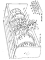
- Figure 1 is a perspective view of an apparatus embodying a preferred embodiment of the invention.
- Figure 2 is a perspective view of a pitted olive that has been sliced by the slicing knives of the apparatus shown in Figure 1.
- Figure 3 is a cross-sectional view taken along line 3-3 of Figure 1.
- Figure 4 is a perspective view of a grooved olive cup of the type included in a preferred embodiment of the invention.
- Figure 5 is a cross-sectional view of the Figure 1 apparatus, taken along line 5-5 of Fig. 3.
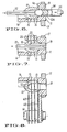
- Figure 6 is a cross-sectional view of a portion of the Figure 1 apparatus, taken along line 6-6 of Figure 3.
- Figure 7 is a cross-sectional view of a portion of the Figure 1 apparatus, taken along line 7-7 of Figure 3.
- Figure 8 is a cross-sectional view of a portion of the Figure 1 apparatus, taken along line 8-8 of Figure 3.
- Figure 9 is a cross-sectional view of another preferred embodiment of a grooved cup that may be included in a preferred embodiment of the inventive system, taken in a plane including the cup's longitudinal axis.
- Figure 10 is a perspective view of an apparatus embodying another preferred embodiment of the invention, in which water jet cutters are employed rather than a set of slicing knives.
- Figure 11 is a cross-sectional view of the Fig. 10 apparatus, taken along line 11-11 of Fig. 10, showing a water jet cutting unit directing four high pressure water jets toward a pitted olive in a grooved cup.
- Each of plunger shafts 21 and 23 is fixedly attached to a pair of members 53 (shown in Figure 5), which members are in turn fixedly attached to shaft 18.
- a coring knife 24 is attached to the end of each of shafts 23.
- a pitting knife 22 is attached to the end of each of shafts 21.
- Plate 17 and members 54 are oriented so that each cup 16 is positioned between one of knives 22 and one of knives 24, so that the longitudinal axis of each component in each combination of these components (knives 22 and 24 and the cup 16 therebetween) coincides with the longitudinal axes of the other components in the combination.
- plate 17 and members 53 rotate as a unit with shaft 18 so that each cup 16, and the knives 22 and 24 spanning the cup, traverse parallel circular paths.
- shaft 61 is mounted on one of frame members 14.
- shaft 61 is rotatably mounted on frame member 14 and a drive means (to be described with reference to Fig. 3 below) is provided for rotating shaft 61 in the direction opposite to the direction in which shaft 18 rotates (so that for example, if shaft 18 rotates clockwise, shaft 61 rotates counterclockwise).
- shaft 18 may be coupled by an appropriate coupling means (which may include a belt) to shaft 61, so that a drive means which powers shaft 18 also drives shaft 61.
- shaft 31 may be fixedly connected to frame member 14 and no drive means provided for shaft 61, so that knives 60 will remain stationary as shaft 18 and cups 16 rotate.
- each knife 60 When a pitted olive in one of cups 16 rotates into engagement with knives 60, each knife 60 acts as a wedge to slice cleanly through the olive as shown in Figure 2.
- four slicing knives 60 (shown by dashed lines) sever the olive engaged therewith into clean slices 10a through 10e.
- Each cup 16 preferably includes grooves 15, which are oriented parallel to the circular path traversed by the cup and parallel to the edges of parallel knives 60.
- the separation between knives 60 matches the separation between grooves 15 so that knives 60 have enough clearance to pass completely through the olive while avoiding cup 16.
- each slicing knife 60 in Figure 1 is shown to have eight lobes (or blades), it is contemplated that each slicing knife may have circular shape or any other shape, provided that each slicing knife has a sharp outer edge.
- Stripper element 31 has stripper bars 31a defining slots for receiving knives 60. Any olive slices clinging to knives 60 will be stripped from the knives as they translate past stripper bars 31a of element 31.
- each olive is positioned in a definite orientation in one of cups 16 when it engages knives 60, the olive slices resulting from operation of knives 60 have uniform size and shape.
- each slicing knife of the inventive system acts simply as a wedge to produce a clean cut through the olive without destroying a significant amount of the olive to produce the cut.
- Any conventional loading means may be employed for loading olives onto cups 16.
- any conventional means may be employed for removing the end product (the pitted olive slices) from the apparatus after the slicing operation.
- Examples of such an end product removal means include an air or water jet (not shown) and stripper member 31.
- Figure 3 is a view taken along line 3-3 of Figure 1 showing a cross-section of the Figure 1 apparatus in a plane perpendicular to the longitudinal axis of shaft 18.
- Chain 40 comprises a plurality of links 44 (two of which are shown in Fig. 3) and extends around a sprocket (not shown) adjustably mounted on member 54 in front of plate 17 (in the Fig. 3 view). Accordingly, chain 40 is only partially shown, since if it were completely shown it would obscure plate 17 and various other elements in Figure 3.
- Locking ring 45 (to be discussed below with reference to Figure 5) is positioned behind (and hence obscured by) plate 17, and has an outer cylindrical surface indicated by dashed line 46 in Figure 3.
- Sprocket 42 (also referred to herein as "star wheel drive 42") is mounted on shaft 61 behind slicing knife 60 (i.e., into the page relative to slicing knife 60) so that sprocket 42 is partially obscured by slicing knife 60.
- the relative size and shape of cups 16 and sprocket 42 are chosen so that the cups 16 (and more specifically, the base portions 11 of cups 16) fit between adjacent teeth 42a of sprocket 42.
- shaft 18, member 54, and plate 17 rotate clockwise (as a unit)
- cups 16 rotate sprocket 42 (and shaft 61 and slicing knives 60 fixedly attached to shaft 61) in a counterclockwise direction.
- sprocket 42 One of the functions of the cups 16 is thus to drive the sprocket 42. Since sprocket 42 and sprocket teeth 42a are fixed relative to slicing blades 60, sprocket 42 also serves a timing function, in the sense that as pairs of adjacent sprocket teeth 42a engage with each cup, such teeth 42a force the cup into a specific orientation relative to the blades of slicing knives 60. Thus, each slicing knife 60 will rotate through the same path relative to each cup as the knife slices an olive in the cup.
- each link 44 extends sufficiently far toward sprocket 42 that the end portions 41 engage with sprocket teeth 42a. Accordingly, when chain 40 rotates clockwise, chain 40 drives sprocket 42 (and shaft 61 and knives 60 fixedly attached to shaft 61) in a counterclockwise direction. In this alternative embodiment it is unnecessary for sprocket teeth 42a to engage with cups 16.
- Mount 25 for holding blades 20 (not shown in Fig. 3) is attached by stationary member 26 (shown in Fig. 1) to one of frame members 14 (shown in Fig. 1). Mount 25 is positioned relative to the path of cups 16 so that holding blades 20 engage the olive in each cup as the cup rotates past mount 25.
- Figure 4 is a perspective view of a preferred embodiment of cup 16.
- Orifice 19 in base portion 11 of cup 16 attached to plate 17 is centered about longitudinal axis 70 of cup 16.
- Base portion 11 extends through plate 17, and is fixedly attached to plate 17.
- one of coring knives 24 extends through orifice 19 to core one end of an olive held in cup 16.
- Cup 16 in Figure 4 includes four grooves 15, each for receiving the edge of a different slicing knive.
- Figure 9 is a cross-sectional view of a preferred embodiment of a grooved cup (identified by reference numeral 16′) that may be used in place of cup 16 (shown in Figure 4) in the inventive system.
- Cup 16′ of Figure 9 is sized and shaped to receive an olive, whose outline is identified by reference numeral 10′.
- the four grooves 15′ in cup 16′ are for receiving slicing knives, as are the four grooves 15 of cup 16.
- grooves 15′ differ from grooves 15 in following respect.
- the ends 72′ of each groove 15′ extend closer to the outer edge of cup 16′ than the ends 72 of each groove 15 extend toward the outer edge of cup 16. Since grooves 15 are longer than grooves 15′, grooves 15′ provide more clearance for the slicing knives than do grooves 15.
- Cup 16′ also includes a resilient insert 13′ within base portion 11′.
- Insert 13′ is ring-shaped, and has a longitudinal axis which coincides with longitudinal axis of cup 16′.
- the inner cylindrical surface of insert 13′ defines orifice 19′, which orifice is oriented to receive one of coring knives 24.
- Insert 13′ may be formed of rubber or another resilient material.
- An advantage of including resilient insert 13′ is that insert 13′ is capable of temporarily deforming to admit an unusually large olive pit, or an olive pit that is mis-oriented with its longitudinal axis perpendicular to axis 70′ of cup 16′.
- orifice 19 of cup 16 in Figure 4 is defined by base portion 11.
- Base portion 11 will typically be composed of a rigid substance (such as rigid plastic), and if so may either fail to admit such an unusually large or mis-oriented pit, causing the inventive system to jam, or may break such a pit as the pit is pressed against base portion 11.
- Figure 5 is a cross-sectional view of the Figure 1 apparatus, taken along line 5-5 of Fig. 3.
- the upper plunger shaft 23 in Figure 5 has been driven by the associated cam follower 36 and member 29 connected thereto into a position fully extended to the left.
- the upper plunger shaft 21 in Figure 5 has been driven by the associated cam follower 30 and member 29 connected thereto into a position fully extended to the right.
- the lower plunger shaft 23 in Figure 5 has been driven by the associated cam follower 36 and member 29 connected thereto into a position fully retracted to the right.
- the lower plunger shaft 21 in Figure 5 has been driven by the associated cam follower 30 and member 29 connected thereto into a position retracted to the left.
- the lower pitting knife 22 and the lower coring knife 24 have been retracted to avoid hitting slicing blades 60 as lower knives 22 and 24 rotate past slicing knives 60.
- Rotating member 53 in turn rotates shafts 23 through a cylindrical region surrounding shaft 18. As shafts 23 rotate, they also translate to the left and to the right as cam followers 36 ride in cam track 34.
- An identical support means (not shown in Figure 5 for simplicity) rotates shafts 21 while allowing them to translate to the right and to the left as cam followers 30 ride in cam track 28.
- Each of ejector rods 55 is slidably positioned inside of one of plungers 23 and is rigidly attached to member 52. As shaft 18 rotates, it causes member 52 to rotate relative to stationary frame members 14. The relative movement between plungers 23 and ejector rods 55 causes removal of pit 11a and olive end piece 12a from the coring knife 24 as each plunger 23 is retracted.
- Locking ring 45 is fitted around the outer surface of cylindrical member 54 to prevent cups 16 from rotating relative to plate 17.
- Base portion 11 of each cup 16 preferably includes an arc-shaped notch having radius of curvature matching the outer radius of ring 45, so that the arc-shaped notch mates with outer cylindrical surface 46 of ring 45. Friction between ring 45, plate 17, and member 54 prevents relative motion therebetween. Since each base portion 11 mates with ring 45, ring 45 holds base portions 11 fixed relative to each other and to ring 45, so that each base portion 11 is held fixed relative to plate 17.
- FIGS 6 and 7 illustrate cup 16 at two positions within a segment of its circular path during which pitting knife 22 and coring knife 24 are translated by the cam means associated therewith into engagement with an olive in the cup, and during which knives 22 and 24 are then retracted from the olive by the cam means.
- pitting knife 22 (which preferably has a cross-shaped cross-section) has penetrated the left end of olive 10 and coring knife 24 (which could be tubular or cross-shaped) has penetrated the right end of olive 10.
- coring knife 24 has begun to retract to the right.
- pitting knife 22 continues to extend to the right, thus pushing pit 11a and end piece 12a of olive 10 to the right, away from the remaining portion of olive 10. End piece 12a would not be present if coring knife 24 is cross-shaped rather than tubular.
- each holding blade 20 be positioned opposite one of grooves 15 in cup 16, and that each slicing knife 60 (shown in Figure 8) also be positioned opposite one of the grooves 15. If so, then the earlier slices made by blades 20 will coincide with the later slices made by knives 60, resulting in an improved appearance for the end product (olive slices) produced by the inventive apparatus. It is contemplated that any number of holding blades 20 may be provided.
- holding blades 20 may be omitted, and cam track 28 shaped so that knives 60 engage the pitted olive while pitting knife 22 has not yet retracted from the olive (i.e., while pitting knife 22 is in the position shown in Figure 7).
- cam track 28 must be shaped so as to retract knife 22 sufficiently rapidly so that knife 22 avoids knives 60.
- Figure 8 illustrates cup 16 when the cup occupies a segment of its circular path in which the pitting operation has been completed and pitting and coring knives have retracted.
- Figure 8 shows wounds 72 in the end of pitted olive 10 that were produced upon retraction of pitting knife 22 from pitted olive 10.
- knives 60 have sliced all the way through pitted olive 10. The edge of each knife 60 extends into a corresponding one of grooves 15 in cup 16.
- knives 60 have produced four clean cuts, which have divided pitted olive 10 into five slices. After the processing stage shown in Figure 8, knives 60 and cup 16 will rotate away from other so that these five slices may then be stripped from knives 60, for example by stripper 31 shown in Figures 1 and 3.
- FIG. 10 differs from the Figure 1 embodiment only in that slicing knives 60 and stripper member 31 are replaced by water jet cutter unit 200.
- Unit 200 includes four high pressure water nozzles 201 mounted on a water manifold 202. Each nozzle 201 emits a jet 203 of high pressure water aimed substantially parallel to the plane of each cup 16's circular path. It is contemplated that a water jet cutter unit having more than four (or less than four) nozzles may be substituted for unit 200 in Figure 10.
- Each water jet will make a cut through an olive in cup 16 in the Figure 10 embodiment, just as each slicing knife 60 will make a cut through the olive in the Figure 1 embodiment.
- the jets are turned on (to slice a pitted olive within one of cups 16) during the period after pitting knife 22 has been retracted, while holding blades 20 are engaged with the pitted olive.
- FIG 11 is a cross-sectional view of the water jet cutter unit 200 of Figure 10, and a pitted olive 10 in a cup 16 adjacent unit 200.
- Pitted olive 10 is in the process of being sliced by four substantially parallel water jets 203 emerging from water nozzles 201.
- Water nozzles 201 are attached to a supply of water within water manifold 202, in a conventional manner.
- the phrase "slicing element" shall be used to denote a member of the broad class of slicing implements including knives and water jets.
- the method of the invention includes the steps of: translating a cup containing an olive to be processed along a portion of a substantially circular cup path; translating a pitting unit along a path substantially parallel to the cup path; while the cup occupies a first segment of the cup path, extending a pitting knife and a coring knife included in the pitting unit into engagement with the olive to extract a pit from the olive, and retracting the pitting and coring knives away from the olive and cup after the pit is extracted; and while the pitted olive remains in the cup with unchanged orientation relative to the cup, translating the cup past a set of slicing elements (such as slicing knives or water jets) in such a manner that the slicing elements engage with and slice the pitted olive in the cup.
- a set of slicing elements such as slicing knives or water jets
- the slicing elements may be accurately pre-positioned to produce pitted olive slices having uniform size and shape.
- the knives may be stationary or they may be rotating when they engage the pitted olive.
- the olive is translated past and engages with one or more holding blades (such as blades 20) during the pitting operation.
- Each holding blade is positioned relative to the cup path so that, when the olive is engaged with the holding blade, the olive is impaled on the pitting knife and the pitting knife is retracting away from the olive in a first direction perpendicular to the cup path, and the holding blade exerts a force on the olive in a second direction opposite the first direction.
- the holding blade holds the pitted olive fixed with respect to the cup while the pitting knife retracts away from the pitted olive.
- the slicing knives may be positioned so as to engage with the pitted olive while the olive is impaled on the pitting knife and the pitting knife is retracting away from the olive in a first direction perpendicular to the cup path.
- the slicing knives exerts a force on the olive in a second direction opposite the first direction, so as to hold the pitted olive fixed with respect to the cup while the pitting knife retracts away from the pitted olive.
- the slicing knives must be positioned so as to avoid penetrating so deeply into the olive (while the olive remains impaled on the pitting knife) that the slicing knives strike the pitting knife.
- the slicing knives instead commence their cuts while the olive is impaled on the pitting knife, and complete their cuts after the pitting knife has retracted away from the pitted olive.
Landscapes
- Life Sciences & Earth Sciences (AREA)
- Engineering & Computer Science (AREA)
- Forests & Forestry (AREA)
- Mechanical Engineering (AREA)
- Chemical & Material Sciences (AREA)
- Food Science & Technology (AREA)
- Polymers & Plastics (AREA)
- Apparatuses For Bulk Treatment Of Fruits And Vegetables And Apparatuses For Preparing Feeds (AREA)
- Food-Manufacturing Devices (AREA)
- Finish Polishing, Edge Sharpening, And Grinding By Specific Grinding Devices (AREA)
- Casting Devices For Molds (AREA)
- Details Of Cutting Devices (AREA)
Claims (29)
- Appareil à dénoyauter et couper en tranches les olives, comprenant :- un arbre menant (18) pouvant tourner ; une plaque (17) reliée fixement à l'arbre menant (18) ;- une première coupelle (16) dimensionnée de façon à recevoir une olive et montée fixement sur la plaque (17) de façon qu'une rotation de l'arbre menant (18) amène la plaque (17) à translater la première coupelle (16), et toute olive se trouvant dans la première coupelle (16) suivant un trajet de coupelles sensiblement circulaire ;- un premier moyen à dénoyauter capable d'effectuer un mouvement d'extension vers la première coupelle (16) lorsque la première coupelle (16) occupe un premier segment du trajet de coupelle pour extraire un noyau d'une olive se trouvant dans la première coupelle (16), le premier moyen (22, 24) à dénoyauter étant également capable de se rétracter de la première coupelle (16) après l'extraction du noyau d'olive ; caractérisé par :- un jeu d'éléments (60) à couper en tranches montés à proximité immédiate d'un second segment du trajet de coupelle, dans une position telle que les éléments (60, 201) à couper en tranches engagent une olive dénoyautée se trouvant dans la première coupelle (16) et la coupent en tranches lorsque la première coupelle (16) occupe le second segment du trajet de coupelle.
- Appareil selon la revendication 1, comprenant aussi :- une deuxième coupelle (16) dimensionnée de façon à recevoir une olive et montée fixement sur la plaque (17) de façon qu'une rotation de l'arbre menant (18) amène la plaque (17) à translater la deuxième coupelle (16), et toute olive se trouvant dans la deuxième coupelle (16), le long dudit trajet de coupelles ;- des deuxièmes moyens à dénoyauter (22, 24) capables d'effectuer un mouvement d'extension vers la deuxième coupelle (16) lorsque la deuxième coupelle (16) occupe le premier segment du trajet de coupelle pour extraire un noyau d'une olive se trouvant dans la deuxième coupelle (16), les deuxièmes moyens (22, 24) à dénoyauter étant également capables de se rétracter de la deuxième coupelle (16) après l'extraction du noyau d'olive : etdans lequel les éléments (60) à couper en tranches engagent une olive dénoyautée se trouvant dans la deuxième coupelle (16) lorsque la deuxième coupelle (16) occupe le second segment du trajet de coupelle, pour couper en tranches l'olive dénoyautée.
- Appareil selon la revendication 1, dans lequel les premiers moyens à dénoyauter (22, 24) comprennent :- un premier élément cylindrique (50) définissant un premier chemin de came (28) ;- un premier couteau à dénoyauter (22) relié à l'arbre menant (18) de manière qu'une rotation de l'arbre menant (18) amène le premier couteau (22) à dénoyauter à effectuer une translation le long d'un trajet de couteau à dénoyauter sensiblement parallèle au trajet de coupelles ;- un premier galet de came (30) se déplaçant dans le premier chemin de came (28) et couplé au premier couteau (22) à dénoyauter afin de pousser d'abord le premier couteau (22) à dénoyauter jusqu'en engagement avec une olive (10) se trouvant dans la première coupelle (16), puis à tirer le premier couteau à dénoyauter (22) hors d'engagement avec l'olive (10), tandis que la première coupelle (16) occupe le premier segment du trajet de coupelles et tandis que le premier couteau (22) à dénoyauter occupe un premier segment du trajet de couteau à dénoyauter ;- un second élément cylindrique (51) définissant un second chemin de came (34) ;- un premier couteau à carotter (24) relié à l'arbre menant (18) de manière qu'une rotation de l'arbre menant (18) amène le premier couteau (24) à carotter à effectuer une translation le long d'un trajet de couteaux à carotter sensiblement parallèle au trajet de coupelles ; et- un second galet de came (36) se déplaçant dans le second chemin de came (34) et couplé au premier couteau à carotter (24) afin de pousser le premier couteau à carotter (24) jusqu'en engagement avec une olive (10) se trouvant dans la première coupelle (16) tandis que la première coupelle (16) occupe le premier segment du trajet de coupelles et tandis que le premier couteau à carotter (24) occupe un premier segment du trajet de couteaux à carotter.
- Appareil selon la revendication 1, dans lequel chaque élément à couper en tranches est un jet d'eau (201).
- Appareil selon la revendication 1, dans lequel chaque élément à couper en tranches est un couteau (60) à couper en tranches.
- Appareil selon la revendication 5, dans lequel les couteaux (60) à couper en tranches restent immobiles pendant que la première coupelle (16) effectue une translation le long du second segment du trajet de coupelle.
- Appareil selon la revendication 5, dans lequel l'arbre menant (18) est capable de tourner dans un premier sens de rotation afin de translater la première coupelle (16) le long du trajet de coupelle dans ledit premier sens de rotation, et comprenant aussi :- un bâti (12) ;- un arbre (61) de couteaux à couper en tranches monté de façon à pouvoir tourner sur le bâti (12) et relié fixement aux couteaux (60) à couper en tranches afin qu'une rotation de l'arbre (61) de couteaux à couper en tranches fasse tourner chaque couteau (60) à couper en tranches ; et
- des moyens (40, 42) de rotation des couteaux à couper en tranches couplés à l'arbre des couteaux à couper en tranches, pour faire tourner l'arbre (61) des couteaux à couper en tranches et les couteaux (60) à couper en tranches, d'un seul bloc, dans un second sens de rotation opposé au premier sens de rotation pendant que la première coupelle (16) effectue une translation le long du second segment du trajet de coupelle. - Appareil selon la revendication 7, dans lequel des moyens (40, 42) de rotation des couteaux à couper en tranches comprennent :- une roue dentée (42) reliée fixement à l'arbre (61) des couteaux à couper en tranches et comportant des dents (42a) de roue, les dents (42a) de roue étant positionnées de façon à engager la première coupelle (16) lorsque la première coupelle (16) effectue une translation le long dudit trajet de coupelle dans ledit premier sens de rotation, afin que la première coupelle (16) entraîne la roue dentée dans ledit second sens de rotation pendant que la première coupelle (16) effectue une translation le long dudit trajet de coupelle dans ledit premier sens de rotation.
- Appareil selon la revendication 7, dans lequel les moyens (40, 42) de rotation des couteaux à couper en tranches comprennent :- une roue dentée (42) reliée fixement à l'arbre (61) des couteaux à couper en tranches ;- une chaîne (40) couplée entre l'arbre menant (18) et la roue dentée (42) de manière qu'une rotation de l'arbre menant (18) dans le premier sens de rotation effectue une translation de la chaîne (40) le long d'un trajet de chaîne dans ledit premier sens de rotation, et que la chaîne (40) fasse tourner la roue dentée (42) dans ledit second sens de rotation pendant que la chaîne (40) tourne le long dudit trajet de chaîne dans ledit premier sens de rotation.
- Appareil selon la revendication 1, dans lequel la première coupelle (16) présente une surface définissant un certain nombre de gorges (15).
- Appareil selon la revendication 10, dans lequel chaque élément (60) à couper en tranches est un couteau (60) à couper en tranches aligné avec l'une des gorges (15) de manière que, lorsque les couteaux (60) à couper en tranches ont coupé en tranches une olive dénoyautée dans la première coupelle (16), chacun des couteaux (60) à couper en tranches pénètre dans la gorge (15) alignée avec lui.
- Appareil selon la revendication 11, dans lequel chaque couteau (60) à couper en tranches comprend un certain nombre de lobes (60) et, lorsque les couteaux (60) à couper en tranches ont coupé en tranches une olive dénoyautée dans la première coupelle (16), chaque couteau (60) à couper en tranches possède un lobe (60) pénétrant dans la gorge (15) alignée avec ledit couteau (60) à couper en tranches.
- Appareil selon la revendication 3, comprenant aussi :- une première lame de maintien (20) montée dans une position telle, à proximité immédiate du premier segment du trajet de coupelles, que la première lame (20) de maintien engage une olive (10) se trouvant dans la première coupelle (16) lorsque la première coupelle (16) occupe le premier segment du trajet de coupelle et que le premier couteau (22) à dénoyauter est engagé avec l'olive, mais est en train d'être retiré de l'engagement avec l'olive, et lorsque la première lame (20) de maintien est engagée avec l'olive, la première lame (20) de maintien exerce une force résistante sur l'olive, s'opposant à la force exercée sur l'olive par le premier couteau (22) à dénoyauter pendant que le premier couteau (22) à dénoyauter est retiré de l'engagement avec l'olive.
- Appareil selon la revendication 13, comprenant aussi une seconde lame (20) de maintien montée dans une position telle, à proximité immédiate du premier segment du trajet de coupelles, que la seconde lame (20) de maintien engage une olive se trouvant dans la première coupelle lorsque la première coupelle (16) occupe le premier segment du trajet de coupelle et que le premier couteau (22) à dénoyauter est engagé avec l'olive, mais est en train d'être retiré de l'engagement avec l'olive, et lorsque la seconde lame (20) de maintien est engagée avec l'olive, la seconde lame (20) de maintien exerce une force résistante sur l'olive (10) s'opposant à la force exercée sur l'olive par le premier couteau (22) à dénoyauter pendant que le premier couteau (22) à dénoyauter est retiré de l'engagement avec l'olive, et dans lequel chacune des première et seconde lames (20) de maintien est alignée avec l'un des éléments à couper en tranches afin que toutes coupes réalisées dans l'olive par les première et seconde lames (20) de maintien s'alignent avec les coupes réalisées ensuite dans l'olive par les éléments (60) à couper en tranches.
- Appareil selon la revendication 3, dans lequel chaque élément à couper en tranches est un couteau (60) à couper en tranches, et les couteaux (60) à couper en tranches sont montés à proximité immédiate du premier segment du trajet de coupelles et à proximité immédiate du second segment du trajet de coupelle, dans une position telle que les couteaux (60) à couper en tranches commencent à engager une olive dénoyautée dans la première coupelle (16) lorsque la première coupelle (16) occupe le premier segment du trajet de coupelle et que le premier couteau (22) à dénoyauter est engagé avec l'olive, et que les couteaux (60) à couper en tranches continuent d'engager l'olive dénoyautée dans la première coupelle (16) lorsque la première coupelle (16) occupe le second segment du trajet de coupelles.
- Appareil à dénoyauter et couper en tranches les olives, comprenant :- un arbre menant (18) pouvant tourner ;- une plaque (17) reliée fixement à l'arbre menant (18) ;- plusieurs coupelles (16), dimensionnées chacune pour recevoir une olive, chaque coupelle (16) étant montée fixement à proximité d'une périphérie extérieure de la plaque (17) afin qu'une rotation de l'arbre menant (18) amène la plaque (17) à translater les coupelles (16), et toutes olives se trouvant dans les coupelles (16), le long d'un trajet de coupelles sensiblement circulaire ;- plusieurs unités à dénoyauter (22, 24), chaque unité (22, 24) à dénoyauter étant montée sur l'arbre menant (18) dans une position adjacente à l'une des coupelles (16) afin qu'une rotation de l'arbre menant (18) amène chaque unité à dénoyauter (22, 24) à se translater d'un seul bloc avec la coupelle (16) qui lui est adjacente, chaque unité à dénoyauter (22, 24) étant capable d'effectuer un mouvement d'extension vers la coupelle (16) qui lui est adjacente lorsque la coupelle (16) occupe un premier segment du trajet de coupelles afin d'extraire un noyau d'une olive se trouvant dans la coupelle (16), et chaque unité à dénoyauter (22, 24) étant également capable de se rétracter de la coupelle (16) qui lui est adjacente après l'extraction du noyau d'olive ; caractérisé par- un jeu d'éléments (60) à couper en tranches montés de façon à être adjacents à un second segment du trajet de coupelles, dans une position telle que les éléments (60) à couper en tranches engagent une olive dénoyautée se trouvant dans chaque coupelle (16) et la coupent en tranches pendant que ladite coupelle (16) parcourt le second segment du trajet de coupelles.
- Appareil selon la revendication 16, dans lequel chaque élément (60) à couper en tranches est un couteau (60) à couper en tranches, et dans lequel l'arbre menant (18) est capable de tourner dans un premier sens de rotation afin de translater les coupelles (16) le long du trajet de coupelle dans ledit premier sens de rotation, et comprenant aussi :- un bâti (12) ;- un arbre (61) de couteaux à couper en tranches monté de façon à pouvoir tourner sur le bâti (12) et relié fixement aux couteaux (60) à couper en tranches afin qu'une rotation de l'arbre (61) des couteaux à couper en tranches fasse tourner chaque couteau (60) à couper en tranches ; et- des moyens (40, 42) de rotation des couteaux à couper en tranches couplés à l'arbre (61) des couteaux à couper en tranches, pour faire tourner l'arbre (61) des couteaux à couper en tranches et les couteaux (60) à couper en tranches, d'un seul bloc, dans un second sens de rotation opposé au premier sens de rotation tandis que les coupelles (16) effectuent une translation le long du trajet de coupelles.
- Appareil selon la revendication 17, dans lequel les moyens (40, 42) de rotation des couteaux à couper en tranches comprennent :- une roue dentée (42) reliée fixement à l'arbre (61) des couteaux à couper en tranches ;- une chaîne (40) couplée entre l'arbre menant (18) et la roue dentée (42) afin qu'une rotation de l'arbre menant (18) dans le premier sens de rotation translate la chaîne (40) le long d'un trajet de chaîne dans ledit premier sens de rotation, et afin que la chaîne (40) fasse tourner la roue dentée (42) dans ledit second sens de rotation pendant que la chaîne (40) tourne le long dudit trajet de chaîne dans ledit premier sens de rotation.
- Appareil selon la revendication 16, dans lequel chaque coupelle (16) présente une surface définissant un certain nombre de gorges (15).
- Appareil selon la revendication 19, dans lequel chaque élément (60) à couper en tranches est un couteau (60) à couper en tranches aligné avec l'une des gorges (15) de manière que, lorsque les couteaux (60) à couper en tranches ont coupé en tranches une olive dénoyautée dans l'une des coupelles (16), chacun des couteaux (60) à couper en tranches pénètre dans la gorge alignée avec lui.
- Appareil selon la revendication 20, dans lequel chaque couteau (60) à couper en tranches comprend un certain nombre de lobes (60) et, lorsque les couteaux à couper en tranches (60) ont coupé en tranches une olive dénoyautée dans l'une des coupelles, chaque couteau (60) à couper en tranches comporte un lobe (60) pénétrant dans la gorge (15) alignée avec ledit couteau (60) à couper en tranches.
- Appareil selon la revendication 16, dans lequel chaque élément (60) à couper en tranches est un couteau (60) à couper en tranches, et les couteaux (60) à couper en tranches restent immobiles pendant que les coupelles (16) effectuent une translation le long du second segment du trajet de coupelle.
- Appareil selon la revendication 16, dans lequel chaque unité (22, 24) à dénoyauter comprend :- un premier élément cylindrique (50) définissant un premier chemin de came (28) ;- un couteau à dénoyauter (22) relié à l'arbre menant (18) de manière qu'une rotation de l'arbre menant (18) amène le couteau à dénoyauter (22) a effectuer une translation le long d'un trajet de couteaux à dénoyauter sensiblement parallèle au trajet de coupelles ;- un premier galet de came (30) se déplaçant dans le premier chemin de came (28) et couplé au couteau (22) à dénoyauter de manière à pousser d'abord le couteau (22) à dénoyauter jusqu'en engagement avec une olive (10) se trouvant dans la coupelle (16) adjacente à l'unité à dénoyauter (22, 24), puis à retirer le couteau à dénoyauter (22) de l'engagement avec l'olive (10), tandis que la coupelle (16) adjacente à l'unité à dénoyauter (22, 24) occupe le premier segment du trajet de coupelle et tandis que le couteau (22) à dénoyauter occupe un premier segment du trajet de couteaux à dénoyauter ;- une second élément cylindrique (51) définissant un second chemin de came (34) ;- un couteau à carotter (24) relié à l'arbre menant (18) de manière qu'une rotation de l'arbre menant (18) amène le couteau à carotter (24) à effectuer une translation le long d'un trajet de couteaux à carotter sensiblement parallèle au trajet de coupelles ; et- un second galet de came (36) se déplaçant dans le second chemin de came (34) et couplé au couteau (24) à carotter de façon à pousser le couteau à carotter (24) jusqu'en engagement avec une olive (10) se trouvant dans la coupelle (16) adjacente à l'unité à dénoyauter (22, 24) tandis que la coupelle (16) occupe le premier segment du trajet de coupelle et tandis que le couteau (24) à carotter occupe un premier segment du trajet de couteaux à carotter.
- Appareil selon la revendication 23, comprenant aussi :- une première plaque de maintien (20) montée dans une position telle, adjacente au premier segment du trajet de coupelle, que la première lame de maintien (20) engage chaque olive (10) se trouvant dans chaque coupelle (16) en translation le long du premier segment du trajet de coupelle tandis que le couteau (22) à dénoyauter est engagé avec ladite olive (10), mais est en train d'être retiré de l'engagement avec la coupelle (10), la première lame de maintien (20) exerçant une force résistante sur l'olive (10) lorsque cette première lame de maintien (20) est engagée avec l'olive (10), ladite force résistante s'opposant à la force exercée sur l'olive (10) par le couteau à dénoyauter pendant que le couteau à dénoyauter est retiré de l'engagement avec l'olive (10).
- Procédé pour dénoyauter et couper en tranches une olive, comprenant les étapes qui consistent :(a) à translater une coupelle (16) contenant une olive le long d'une partie d'un trajet de coupelles sensiblement circulaire ;(b) à translater une unité à dénoyauter (22, 24), comprenant un couteau à dénoyauter (22) et un couteau à carotter (24), le long d'un trajet sensiblement parallèle au trajet de coupelles ;(c) tandis que la coupelle (16) occupe un premier segment du trajet de coupelle, à effectuer un mouvement d'extension du couteau à dénoyauter (22) et du couteau à carotter (24) depuis l'unité à dénoyauter (22, 24) jusqu'en engagement avec l'olive se trouvant dans la coupelle (16) pour extraire un noyau de l'olive ; et(d) à rétracter les couteaux à dénoyauter et à carotter (22, 24) à l'écart de la coupelle (16) après que le noyau a été extrait ;
caractérisé par l'étape qui consiste :(e) tandis que l'olive dénoyautée reste dans la coupelle (16) dans une orientation non modifiée par rapport à la coupelle (16), à translater la coupelle (16) au-delà d'un jeu d'éléments (60) à couper en tranches de manière que les éléments (60) à couper en tranches engagent l'olive dénoyautée se trouvant dans la coupelle (16) et la coupent en tranches. - Procédé selon la revendication 25, comprenant aussi l'étape qui consiste :(f) tandis que l'olive est empalée sur le couteau (22) à dénoyauter et que le couteau (22) à dénoyauter se rétracte de l'olive empalée sur lui dans un premier sens perpendiculaire au trajet de coupelles, à translater la coupelle (16) au-delà d'une lame (20) de maintien, ladite lame (20) de maintien étant positionnée de façon que la lame (20) de maintien engage l'olive et exerce sur l'olive une force dans un second sens opposé au premier sens.
- Procédé selon la revendication 26, dans lequel la lame (20) de maintien maintient l'olive dénoyautée en position fixe par rapport à la coupelle (16) tandis que le couteau (22) à dénoyauter se rétracte de l'olive dénoyautée.
- Procédé selon la revendication 25, dans lequel chaque élément (60) à couper en tranches est un couteau (60) à couper en tranches, et les couteaux (60) à couper en tranches sont positionnés de façon à engager l'olive dénoyautée tandis que celle-ci est empalée sur le couteau (22) à dénoyauter et que le couteau (22) à dénoyauter est rétracté de l'olive dénoyautée empalée sur lui dans un premier sens perpendiculaire au trajet de coupelles.
- Procédé selon la revendication 28, dans lequel les couteaux (60) à couper en tranches exercent sur l'olive une force dans un second sens opposé au premier sens afin de maintenir l'olive dénoyautée en position fixe par rapport à la coupelle (16) tandis que le couteau (22) à dénoyauter se rétracte de l'olive dénoyautée.
Priority Applications (1)
| Application Number | Priority Date | Filing Date | Title |
|---|---|---|---|
| AT88120036T ATE80979T1 (de) | 1988-01-13 | 1988-12-01 | Verfahren und vorrichtung zum entkernen und schneiden von oliven. |
Applications Claiming Priority (4)
| Application Number | Priority Date | Filing Date | Title |
|---|---|---|---|
| US07/143,822 US4876954A (en) | 1988-01-13 | 1988-01-13 | Method and apparatus for pitting and slicing olives |
| US07/240,153 US4925691A (en) | 1988-01-13 | 1988-09-02 | Method and apparatus for pitting and slicing olives |
| US240153 | 1988-09-02 | ||
| US143822 | 1998-08-31 |
Publications (3)
| Publication Number | Publication Date |
|---|---|
| EP0324094A2 EP0324094A2 (fr) | 1989-07-19 |
| EP0324094A3 EP0324094A3 (fr) | 1991-01-30 |
| EP0324094B1 true EP0324094B1 (fr) | 1992-09-30 |
Family
ID=26841425
Family Applications (1)
| Application Number | Title | Priority Date | Filing Date |
|---|---|---|---|
| EP88120036A Expired - Lifetime EP0324094B1 (fr) | 1988-01-13 | 1988-12-01 | Procédé et dispositif pour dénoyauter et couper des olives |
Country Status (5)
| Country | Link |
|---|---|
| US (1) | US4925691A (fr) |
| EP (1) | EP0324094B1 (fr) |
| AT (1) | ATE80979T1 (fr) |
| DE (1) | DE3875098T2 (fr) |
| ES (1) | ES2009731T3 (fr) |
Families Citing this family (12)
| Publication number | Priority date | Publication date | Assignee | Title |
|---|---|---|---|---|
| IT1242616B (it) * | 1990-12-12 | 1994-05-16 | Marco Pennesi | Macchina per il riempimento automatico, con pastella di carne, di olive snocciolate. |
| US5325769A (en) * | 1992-09-25 | 1994-07-05 | Filembak, Inc. | Walnut cracking mechanism |
| US5528967A (en) * | 1993-07-19 | 1996-06-25 | Marenco Corporation | Fluid jet fruit slicer |
| FR2817556B1 (fr) * | 2000-12-01 | 2005-02-11 | Jean Pierre Martel | Procede et appareil de valorisation integrale des drupes oleiferes, en particulier des olives et les produits specifiques obtenus |
| US6969535B2 (en) * | 2004-02-25 | 2005-11-29 | Ashlock Company, A Division Of Vistan Corporation | Method for pitting and slicing olives with spring-loaded, adjustable slicing knife assembly |
| US7779752B1 (en) * | 2004-12-28 | 2010-08-24 | Ellison Thomas E | Food item pitting or coring and stuffing device |
| US20060156931A1 (en) * | 2005-01-19 | 2006-07-20 | Mather Donald A | Breading machine and methods of operation |
| US9578896B2 (en) | 2012-03-21 | 2017-02-28 | Ashlock Company, A Division Of Vistan Corporation | Apparatus for scarifying fruit using opposed knives |
| CN103798915B (zh) * | 2014-03-10 | 2015-10-07 | 江苏楷益智能科技有限公司 | 一种大枣去核切片一体机 |
| CN105747238A (zh) * | 2016-04-03 | 2016-07-13 | 申翰昭 | 一种高效莲子去芯设备 |
| CN114426189B (zh) * | 2022-01-20 | 2023-09-01 | 浙江大象新型材料有限公司 | 一种折叠式物料输送设备 |
| US20240180225A1 (en) * | 2022-12-06 | 2024-06-06 | Johnson Foods, Inc. | Water-based cutting mechanism for pitted fruit |
Family Cites Families (23)
| Publication number | Priority date | Publication date | Assignee | Title |
|---|---|---|---|---|
| US1204413A (en) * | 1913-04-26 | 1916-11-14 | Burton C Coons | Paring-machine. |
| US1441490A (en) * | 1922-11-10 | 1923-01-09 | E H Duncan | Method of preparing fruit for canning |
| US2035912A (en) * | 1931-07-08 | 1936-03-31 | Pacific Machinery Co | Fruit pitting, stemming, and slicing machine |
| US2097170A (en) * | 1936-11-23 | 1937-10-26 | Wilson Edwin Earl | Paring, slicing, and coring machine |
| US2205397A (en) * | 1937-08-23 | 1940-06-25 | Lindsay Ripe Olive Company | Automatic pitting machine |
| US2246843A (en) * | 1938-12-13 | 1941-06-24 | Lindsay Ripe Olive Company | Automatic olive pitting machine |
| US2360103A (en) * | 1941-11-10 | 1944-10-10 | Fmc Corp | Olive-pitting machine |
| US2360411A (en) * | 1942-06-30 | 1944-10-17 | Frova Giovanni | Automatic apparatus for aligning and pitting olives, etc. |
| US2681089A (en) * | 1949-08-06 | 1954-06-15 | Marshall E Francisco | Pitting and stuffing apparatus |
| US2641088A (en) * | 1949-09-26 | 1953-06-09 | North American Aviation Inc | Worm gear lapping apparatus |
| US2821223A (en) * | 1955-10-17 | 1958-01-28 | Lindsay Ripe Olive Company | Pit dislodgment jets for fruit pitting machine |
| US4096795A (en) * | 1976-02-03 | 1978-06-27 | Ser Gonzalez Clemente Del | Olive pitting and stuffing machine |
| US4388858A (en) * | 1978-07-10 | 1983-06-21 | Vistan Corporation | Machine for pitting and stuffing olives |
| US4220080A (en) * | 1978-07-10 | 1980-09-02 | Vistan Corporation | Machine for pitting and stuffing olives |
| ES474942A1 (es) * | 1978-11-08 | 1980-01-16 | Ser Gonzalez Clemente Del | Mejoras introducidas en las maquinas deshuesadoras rellena- doras de aceitunas |
| US4308292A (en) * | 1979-07-02 | 1981-12-29 | Silvestrini J A | Method for producing pitted olives |
| US4363266A (en) * | 1980-10-07 | 1982-12-14 | Atlas Pacific Engineering Company | Machine for slicing unpeeled apples into rings |
| ES521254A0 (es) * | 1983-04-06 | 1984-10-01 | Sadrym | Maquina rodajadora de frutos. |
| ES8606784A1 (es) * | 1984-11-21 | 1985-11-01 | Racionalizacion Y Mecanizacion | Mejoras introducidas en maquinas deshueso-rellenadoras de aceitunas |
| US4727802A (en) * | 1987-01-08 | 1988-03-01 | Ser Gonzalez Clemente Del | Fruit pitting machine |
| ES2003675A6 (es) * | 1987-01-30 | 1988-11-01 | Racionalizacion Y Mecanizacion | Maquina rodajadora de frutos |
| US4876954A (en) * | 1988-01-13 | 1989-10-31 | Ashlock Company | Method and apparatus for pitting and slicing olives |
| US4871568A (en) * | 1988-03-23 | 1989-10-03 | Ashlock Company | Method for pitting olives |
-
1988
- 1988-09-02 US US07/240,153 patent/US4925691A/en not_active Expired - Lifetime
- 1988-12-01 ES ES198888120036T patent/ES2009731T3/es not_active Expired - Lifetime
- 1988-12-01 DE DE8888120036T patent/DE3875098T2/de not_active Expired - Fee Related
- 1988-12-01 AT AT88120036T patent/ATE80979T1/de active
- 1988-12-01 EP EP88120036A patent/EP0324094B1/fr not_active Expired - Lifetime
Also Published As
| Publication number | Publication date |
|---|---|
| EP0324094A2 (fr) | 1989-07-19 |
| DE3875098T2 (de) | 1993-02-25 |
| US4925691A (en) | 1990-05-15 |
| DE3875098D1 (de) | 1992-11-05 |
| ATE80979T1 (de) | 1992-10-15 |
| EP0324094A3 (fr) | 1991-01-30 |
| ES2009731T3 (es) | 1993-04-16 |
| ES2009731A4 (es) | 1989-10-16 |
Similar Documents
| Publication | Publication Date | Title |
|---|---|---|
| US4925691A (en) | Method and apparatus for pitting and slicing olives | |
| JP3409914B2 (ja) | ナシ処理方法およびその装置 | |
| US5996482A (en) | Specification | |
| US3473588A (en) | Method and means for peeling pineapples | |
| EP0376390B1 (fr) | Procédé et machine permettant d'extraire le jus et la pulpe de fruits | |
| US4727802A (en) | Fruit pitting machine | |
| US2139704A (en) | Fruit preparation machine | |
| US4985268A (en) | Method for processing pineapples | |
| US3638696A (en) | Means for peeling pineapples | |
| US4876954A (en) | Method and apparatus for pitting and slicing olives | |
| US3195594A (en) | Material cutting machine | |
| US6969535B2 (en) | Method for pitting and slicing olives with spring-loaded, adjustable slicing knife assembly | |
| US4363266A (en) | Machine for slicing unpeeled apples into rings | |
| US2570071A (en) | Apparatus for peeling fruit | |
| US3568743A (en) | Coring device for pineapple sizing machines | |
| US4871568A (en) | Method for pitting olives | |
| US2549333A (en) | Method for sectionizing citrus fruits | |
| US4129068A (en) | Citrus slicing apparatus | |
| US2034160A (en) | Automatic pineapple machine | |
| US7779752B1 (en) | Food item pitting or coring and stuffing device | |
| US2179529A (en) | Pear preparation machine | |
| US3734002A (en) | Means for peeling pineapples | |
| US3678976A (en) | Onion peeling apparatus | |
| US1785002A (en) | Fruit pitting and coring apparatus | |
| US3246678A (en) | Pineapple treating process and apparatus |
Legal Events
| Date | Code | Title | Description |
|---|---|---|---|
| PUAI | Public reference made under article 153(3) epc to a published international application that has entered the european phase |
Free format text: ORIGINAL CODE: 0009012 |
|
| AK | Designated contracting states |
Kind code of ref document: A2 Designated state(s): AT BE CH DE ES FR GB GR IT LI LU NL SE |
|
| PUAL | Search report despatched |
Free format text: ORIGINAL CODE: 0009013 |
|
| AK | Designated contracting states |
Kind code of ref document: A3 Designated state(s): AT BE CH DE ES FR GB GR IT LI LU NL SE |
|
| 17P | Request for examination filed |
Effective date: 19910506 |
|
| 17Q | First examination report despatched |
Effective date: 19910710 |
|
| GRAA | (expected) grant |
Free format text: ORIGINAL CODE: 0009210 |
|
| AK | Designated contracting states |
Kind code of ref document: B1 Designated state(s): AT BE CH DE ES FR GB GR IT LI LU NL SE |
|
| PG25 | Lapsed in a contracting state [announced via postgrant information from national office to epo] |
Ref country code: GR Free format text: LAPSE BECAUSE OF FAILURE TO SUBMIT A TRANSLATION OF THE DESCRIPTION OR TO PAY THE FEE WITHIN THE PRESCRIBED TIME-LIMIT Effective date: 19920930 Ref country code: SE Effective date: 19920930 Ref country code: AT Effective date: 19920930 |
|
| REF | Corresponds to: |
Ref document number: 80979 Country of ref document: AT Date of ref document: 19921015 Kind code of ref document: T |
|
| ITF | It: translation for a ep patent filed | ||
| REF | Corresponds to: |
Ref document number: 3875098 Country of ref document: DE Date of ref document: 19921105 |
|
| ET | Fr: translation filed | ||
| PG25 | Lapsed in a contracting state [announced via postgrant information from national office to epo] |
Ref country code: GB Effective date: 19921230 |
|
| PG25 | Lapsed in a contracting state [announced via postgrant information from national office to epo] |
Ref country code: LU Free format text: LAPSE BECAUSE OF NON-PAYMENT OF DUE FEES Effective date: 19921231 |
|
| REG | Reference to a national code |
Ref country code: ES Ref legal event code: FG2A Ref document number: 2009731 Country of ref document: ES Kind code of ref document: T3 |
|
| PLBE | No opposition filed within time limit |
Free format text: ORIGINAL CODE: 0009261 |
|
| STAA | Information on the status of an ep patent application or granted ep patent |
Free format text: STATUS: NO OPPOSITION FILED WITHIN TIME LIMIT |
|
| GBPC | Gb: european patent ceased through non-payment of renewal fee |
Effective date: 19921230 |
|
| 26N | No opposition filed | ||
| PGFP | Annual fee paid to national office [announced via postgrant information from national office to epo] |
Ref country code: DE Payment date: 19951128 Year of fee payment: 8 |
|
| PGFP | Annual fee paid to national office [announced via postgrant information from national office to epo] |
Ref country code: FR Payment date: 19951212 Year of fee payment: 8 |
|
| PGFP | Annual fee paid to national office [announced via postgrant information from national office to epo] |
Ref country code: CH Payment date: 19951229 Year of fee payment: 8 |
|
| PGFP | Annual fee paid to national office [announced via postgrant information from national office to epo] |
Ref country code: NL Payment date: 19951230 Year of fee payment: 8 |
|
| PGFP | Annual fee paid to national office [announced via postgrant information from national office to epo] |
Ref country code: BE Payment date: 19960109 Year of fee payment: 8 |
|
| PG25 | Lapsed in a contracting state [announced via postgrant information from national office to epo] |
Ref country code: LI Effective date: 19961231 Ref country code: CH Effective date: 19961231 Ref country code: BE Effective date: 19961231 |
|
| BERE | Be: lapsed |
Owner name: ASHLOCK CY DIVISION OF VISTAN CORP. Effective date: 19961231 |
|
| PG25 | Lapsed in a contracting state [announced via postgrant information from national office to epo] |
Ref country code: NL Effective date: 19970701 |
|
| REG | Reference to a national code |
Ref country code: CH Ref legal event code: PL |
|
| PG25 | Lapsed in a contracting state [announced via postgrant information from national office to epo] |
Ref country code: FR Effective date: 19970829 |
|
| NLV4 | Nl: lapsed or anulled due to non-payment of the annual fee |
Effective date: 19970701 |
|
| PG25 | Lapsed in a contracting state [announced via postgrant information from national office to epo] |
Ref country code: DE Effective date: 19970902 |
|
| REG | Reference to a national code |
Ref country code: FR Ref legal event code: ST |
|
| PGFP | Annual fee paid to national office [announced via postgrant information from national office to epo] |
Ref country code: ES Payment date: 20080118 Year of fee payment: 20 |
|
| PGFP | Annual fee paid to national office [announced via postgrant information from national office to epo] |
Ref country code: IT Payment date: 20071228 Year of fee payment: 20 |
|
| REG | Reference to a national code |
Ref country code: ES Ref legal event code: FD2A Effective date: 20081202 |
|
| PG25 | Lapsed in a contracting state [announced via postgrant information from national office to epo] |
Ref country code: ES Free format text: LAPSE BECAUSE OF EXPIRATION OF PROTECTION Effective date: 20081202 |