EP0324105A2 - Dispositif avec au moins une magnétorésistance dans un boîtier - Google Patents
Dispositif avec au moins une magnétorésistance dans un boîtier Download PDFInfo
- Publication number
- EP0324105A2 EP0324105A2 EP88120392A EP88120392A EP0324105A2 EP 0324105 A2 EP0324105 A2 EP 0324105A2 EP 88120392 A EP88120392 A EP 88120392A EP 88120392 A EP88120392 A EP 88120392A EP 0324105 A2 EP0324105 A2 EP 0324105A2
- Authority
- EP
- European Patent Office
- Prior art keywords
- magnetic field
- dependent resistor
- permanent magnet
- housing
- dependent
- Prior art date
- Legal status (The legal status is an assumption and is not a legal conclusion. Google has not performed a legal analysis and makes no representation as to the accuracy of the status listed.)
- Withdrawn
Links
Images
Classifications
-
- G—PHYSICS
- G01—MEASURING; TESTING
- G01D—MEASURING NOT SPECIALLY ADAPTED FOR A SPECIFIC VARIABLE; ARRANGEMENTS FOR MEASURING TWO OR MORE VARIABLES NOT COVERED IN A SINGLE OTHER SUBCLASS; TARIFF METERING APPARATUS; MEASURING OR TESTING NOT OTHERWISE PROVIDED FOR
- G01D5/00—Mechanical means for transferring the output of a sensing member; Means for converting the output of a sensing member to another variable where the form or nature of the sensing member does not constrain the means for converting; Transducers not specially adapted for a specific variable
- G01D5/12—Mechanical means for transferring the output of a sensing member; Means for converting the output of a sensing member to another variable where the form or nature of the sensing member does not constrain the means for converting; Transducers not specially adapted for a specific variable using electric or magnetic means
- G01D5/14—Mechanical means for transferring the output of a sensing member; Means for converting the output of a sensing member to another variable where the form or nature of the sensing member does not constrain the means for converting; Transducers not specially adapted for a specific variable using electric or magnetic means influencing the magnitude of a current or voltage
- G01D5/142—Mechanical means for transferring the output of a sensing member; Means for converting the output of a sensing member to another variable where the form or nature of the sensing member does not constrain the means for converting; Transducers not specially adapted for a specific variable using electric or magnetic means influencing the magnitude of a current or voltage using Hall-effect devices
- G01D5/147—Mechanical means for transferring the output of a sensing member; Means for converting the output of a sensing member to another variable where the form or nature of the sensing member does not constrain the means for converting; Transducers not specially adapted for a specific variable using electric or magnetic means influencing the magnitude of a current or voltage using Hall-effect devices influenced by the movement of a third element, the position of Hall device and the source of magnetic field being fixed in respect to each other
Definitions
- the invention relates to a device with at least one magnetic field-dependent resistor arranged in a housing according to the preamble of claim 1.
- Such a device is known from Volvo Technical Information 840323.
- This contains a sensor, which consists of magnetic field dependent resistors housed in a housing, and a permanent magnet attached to the moving object.
- a small distance between the magnetic field-dependent resistors and the moving part, in this case the permanent magnet is aimed for.
- the short distance required requires a correspondingly thin housing wall of the sensor, which protects the magnetic field-dependent resistors.
- this thin housing wall can also be pressed in slightly, as a result of which the magnetic field-dependent resistors applied to a fragile substrate can be destroyed.
- the invention is intended to achieve the object of designing the device of the type mentioned in such a way that good protection of the magnetic field-dependent resistors is achieved even with a small distance between the parts which can be moved past is guaranteed. High sensitivity should therefore be achieved without the risk of the device being easily destroyed.
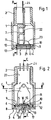
- a front plate 4 which seals the housing, is fastened in a preferably cylindrical, tubular housing part 1 with an end screw attachment 2 on the front side 3. This can be done e.g. by means of locking hooks and protrusions and / or gluing the front panel 4.
- Fastening pins 6 are provided on the rear side 5 of the front plate 4.
- a carrier 7 provided with bores 8 can be plugged onto this.
- the two components are rigidly attached to one another by gluing or welding and / or by plastic, in particular thermoplastic, deformation of the ends 9 of the fastening pins 6 which project beyond the bore 8.
- At least one magnetic field-dependent resistor 11, a spacer plate 12 and a permanent magnet 13 located on a substrate 10 are arranged one behind the other between the carrier 7 and the rear side 5 of the front plate 4.
- the latter designed as a bar magnet, is fastened in a recess 14 on the rear side 5 of the front plate 4.
- fastening strips or fastening pins can also be provided.
- a part of the rear stray field 15 penetrates the magnetic field-dependent resistor 11, which prevents the transverse field, i.e. a field line component perpendicular to the pole center line 16, corresponding resistance value.
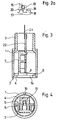
- a toothed ferromagnetic part 17 moved past the front plate 4 changes the leakage flux if, for example, a tooth 18 instead of a gap 19 comes into the effective range of the outer leakage field 20 (cf. FIG. 2a). If there is a ferromagnetic part in the outer stray field 20, then it also increases the transverse component of the rear stray field 15, in which the magnetic field-dependent resistor 11 is located. This causes a significant change in resistance, usually an increase in resistance, of the magnetic field-dependent resistor 11.
- Fig. 2 there is only a strip-shaped magnetic field dependent resistor 11.
- a plurality of magnetic field-dependent resistors in particular interconnected to form a bridge circuit.
- the width of the permanent magnet 13 is preferably somewhat larger than that of the magnetic field-dependent resistor. In particular, it projects laterally by about half to the entire width of the magnetic field-dependent resistor 11.
- a circuit board 22 for example a printed circuit with soldered electrical components or a thick film circuit, is fastened on the carrier 7.
- the circuit board 22 is provided with an electronic evaluation circuit. It is connected in an electrically conductive manner via leads 23 to the magnetic field-dependent resistors 11.
- the connections 24 of the circuit board 22 protrude from the housing part 1.
- the latter can be made from the side of the screw attachment 2 with an insulating casting compound, in particular one Epoxy resin or polyester resin. This gives you a very stable sensor that can also withstand greater loads on the front.
Landscapes
- Physics & Mathematics (AREA)
- General Physics & Mathematics (AREA)
- Measuring Magnetic Variables (AREA)
- Transmission And Conversion Of Sensor Element Output (AREA)
- Adjustable Resistors (AREA)
Applications Claiming Priority (2)
| Application Number | Priority Date | Filing Date | Title |
|---|---|---|---|
| DE3800824A DE3800824A1 (de) | 1988-01-14 | 1988-01-14 | Vorrichtung mit wenigstens einem in einem gehaeuse angeordneten magnetfeldabhaengigen widerstand |
| DE3800824 | 1988-01-14 |
Publications (2)
| Publication Number | Publication Date |
|---|---|
| EP0324105A2 true EP0324105A2 (fr) | 1989-07-19 |
| EP0324105A3 EP0324105A3 (fr) | 1991-01-30 |
Family
ID=6345227
Family Applications (1)
| Application Number | Title | Priority Date | Filing Date |
|---|---|---|---|
| EP19880120392 Withdrawn EP0324105A3 (fr) | 1988-01-14 | 1988-12-07 | Dispositif avec au moins une magnétorésistance dans un boítier |
Country Status (3)
| Country | Link |
|---|---|
| US (1) | US4975675A (fr) |
| EP (1) | EP0324105A3 (fr) |
| DE (1) | DE3800824A1 (fr) |
Cited By (1)
| Publication number | Priority date | Publication date | Assignee | Title |
|---|---|---|---|---|
| WO2019110304A1 (fr) * | 2017-12-05 | 2019-06-13 | Sensitec Gmbh | Capteur de champ magnétique |
Families Citing this family (17)
| Publication number | Priority date | Publication date | Assignee | Title |
|---|---|---|---|---|
| DE4113201A1 (de) * | 1991-04-23 | 1992-10-29 | Oplaender Wilo Werk Gmbh | Verfahren zur beruehrungslosen kontrolle der drehrichtung elektrischer maschinen |
| DE4137915A1 (de) * | 1991-11-18 | 1993-05-19 | Teves Gmbh Alfred | Hydraulischer regelbarer schwingungsdaempfer |
| DE4140403C2 (de) * | 1991-12-07 | 1994-11-24 | Mannesmann Kienzle Gmbh | Verfahren zur Montage eines Sensorkopfes für einen Magnetfeldgeber |
| US5293125A (en) * | 1992-01-17 | 1994-03-08 | Lake Shore Cryotronics, Inc. | Self-aligning tachometer with interchangeable elements for different resolution outputs |
| US5336994A (en) * | 1992-11-20 | 1994-08-09 | Lake Shore Cryotronics, Inc. | Magneto-resistive tachometer assembly with reversible cover and related method |
| US5495758A (en) * | 1993-06-17 | 1996-03-05 | Lake Shore Cryotronics, Inc. | Tachometer assembly with integral internal wrench |
| DE4324621A1 (de) * | 1993-07-22 | 1995-01-26 | Teves Gmbh Alfred | Vorrichtung zum Erfassen einer Drehbewegung |
| DE4324622A1 (de) * | 1993-07-22 | 1995-01-26 | Teves Gmbh Alfred | Vorrichtung zum Erfassen einer Drehbewegung |
| US5514955A (en) * | 1994-03-11 | 1996-05-07 | Lake Shore Cryotronics, Inc. | Slim profile digital tachometer including planar block and rotor having spokes and clamp |
| US6246233B1 (en) | 1994-12-30 | 2001-06-12 | Northstar Technologies Inc. | Magnetoresistive sensor with reduced output signal jitter and temperature compensation |
| DE19618631A1 (de) * | 1996-05-09 | 1997-11-13 | Teves Gmbh Alfred | Vorrichtung zur Messung von Dreh- oder Winkelbewegungen und ein Verfahren zur Herstellung dieser Vorrichtung |
| DE19806722A1 (de) * | 1998-02-18 | 1999-08-19 | Itt Mfg Enterprises Inc | Sensor |
| DE19909109A1 (de) * | 1999-03-03 | 2000-09-07 | Fev Motorentech Gmbh | Verfahren zur Erfassung der Ankerbewegung an einem elektromagnetischen Aktuator |
| DE19928565A1 (de) * | 1999-06-22 | 2001-01-11 | Tyco Electronics Logistics Ag | Befestigungsvorrichtung und Verfahren zum Befestigen eines optoelektrischen Wandlerbausteins an einer Stiftleiste |
| DE10018269B4 (de) * | 2000-04-13 | 2009-04-09 | Dr. Johannes Heidenhain Gmbh | Abtasteinheit |
| DE20200330U1 (de) | 2002-01-10 | 2002-07-04 | ASM Automation Sensorik Meßtechnik GmbH, 85452 Moosinning | Messvorrichtungs-Kopf mit Frontplatte |
| DE10313643B4 (de) * | 2003-03-26 | 2007-08-09 | Highresolution Gmbh | Positionsmesssystem |
Family Cites Families (7)
| Publication number | Priority date | Publication date | Assignee | Title |
|---|---|---|---|---|
| JPS4854957A (fr) * | 1971-11-08 | 1973-08-02 | ||
| FR2245930A1 (en) * | 1973-07-26 | 1975-04-25 | Peugeot & Renault | Magnetic position sensor - has magnetic fiel field sensitive semiconductor element and samarium cobalt magnet |
| US4088977A (en) * | 1977-02-02 | 1978-05-09 | Illinois Tool Works Inc. | Contactless linear position sensor |
| US4737710A (en) * | 1983-01-27 | 1988-04-12 | Trw Inc. | Hall-effect array for sensing second spatial derivative of magnetic field |
| JPS6046462A (ja) * | 1983-08-23 | 1985-03-13 | Fuji Heavy Ind Ltd | 回転センサ |
| JPS6082918A (ja) * | 1983-10-14 | 1985-05-11 | Hitachi Ltd | 回転検出器 |
| DE3620884A1 (de) * | 1986-06-21 | 1987-12-23 | Dietrich Gruenau Gmbh & Co Kg | Vorrichtung zur erfassung von drehzahl und drehrichtung eines drehenden teils |
-
1988
- 1988-01-14 DE DE3800824A patent/DE3800824A1/de not_active Withdrawn
- 1988-12-07 EP EP19880120392 patent/EP0324105A3/fr not_active Withdrawn
- 1988-12-22 US US07/288,151 patent/US4975675A/en not_active Expired - Fee Related
Cited By (2)
| Publication number | Priority date | Publication date | Assignee | Title |
|---|---|---|---|---|
| WO2019110304A1 (fr) * | 2017-12-05 | 2019-06-13 | Sensitec Gmbh | Capteur de champ magnétique |
| US11307269B2 (en) | 2017-12-05 | 2022-04-19 | Sensitec Gmbh | Magnetic field sensor |
Also Published As
| Publication number | Publication date |
|---|---|
| US4975675A (en) | 1990-12-04 |
| EP0324105A3 (fr) | 1991-01-30 |
| DE3800824A1 (de) | 1989-07-27 |
Similar Documents
| Publication | Publication Date | Title |
|---|---|---|
| EP0324105A2 (fr) | Dispositif avec au moins une magnétorésistance dans un boîtier | |
| DE69729534T2 (de) | Magnetischer Fühler | |
| DE19680088B4 (de) | Kalibrier- und Herstellungsverfahren für einen Magnetsensor | |
| DE602005003777T2 (de) | Oberflächenmontierter integrierter Stromsensor | |
| EP0807256A1 (fr) | Dispositif permettant de mesurer la vitesse de rotation ou de detecter le sens de rotation d'un champ magnetique rotatif | |
| DE102007020882B4 (de) | Einrichtung zur Überprüfung der Befestigung einer Leiterbahnplatte an einem Träger | |
| DE102011107703A1 (de) | Integrierter Stromsensor | |
| DE20211518U1 (de) | Als Hall-Sensor ausgebildeter Positionssensor | |
| DE102014014050A1 (de) | Näherungssensoranordnung | |
| DE4219923C2 (de) | Magnet-Sensor | |
| EP1811272A2 (fr) | Dispositif de détection | |
| EP0188789B1 (fr) | Capteur de champ magnétique | |
| DE10018269B4 (de) | Abtasteinheit | |
| DE4137690A1 (de) | Gedruckte verdrahtungs- und/oder schaltungskarte oder -platte sowie anwendung derselben in einer elektronischen einrichtung | |
| DE3620884A1 (de) | Vorrichtung zur erfassung von drehzahl und drehrichtung eines drehenden teils | |
| DE202004002348U1 (de) | Kurbelwellengeber | |
| DE19535714C1 (de) | Statuszeigeeinrichtung für Leiterplattenanschlußelemente | |
| DE4219907C2 (de) | Magnetischer Sensor | |
| DE10159063B4 (de) | Vorrichtung zur lagerichtigen Befestigung einer Leiterplatte | |
| DE10053314B4 (de) | Vorrichtung zum Messen der Sauertoffkonzentration in Gasen | |
| DE19746075A1 (de) | Meßwertaufnehmer zur Erfassung der elektrischen Leitfähigkeit eines flüssigen Mediums | |
| DE19839118C2 (de) | Konstruktionsanordnung für die Befestigung eines Bauelements auf einer gedruckten Leiterplatte und elektronische Geräte mit dieser Konstruktion | |
| EP0540955B1 (fr) | Dispositif pour fixer un aimant permanent en forme de barre | |
| DE202019107291U1 (de) | Sensoranordnung, Sensorvorrichtung sowie zugehörige Verwendung | |
| DE10106479B4 (de) | Magnetische Längemeßvorrichtung |
Legal Events
| Date | Code | Title | Description |
|---|---|---|---|
| PUAI | Public reference made under article 153(3) epc to a published international application that has entered the european phase |
Free format text: ORIGINAL CODE: 0009012 |
|
| AK | Designated contracting states |
Kind code of ref document: A2 Designated state(s): BE DE FR GB SE |
|
| PUAL | Search report despatched |
Free format text: ORIGINAL CODE: 0009013 |
|
| AK | Designated contracting states |
Kind code of ref document: A3 Designated state(s): BE DE FR GB SE |
|
| STAA | Information on the status of an ep patent application or granted ep patent |
Free format text: STATUS: THE APPLICATION IS DEEMED TO BE WITHDRAWN |
|
| 18D | Application deemed to be withdrawn |
Effective date: 19910731 |