EP0324112B1 - Adjusting device for a setting bolt - Google Patents
Adjusting device for a setting bolt Download PDFInfo
- Publication number
- EP0324112B1 EP0324112B1 EP88120649A EP88120649A EP0324112B1 EP 0324112 B1 EP0324112 B1 EP 0324112B1 EP 88120649 A EP88120649 A EP 88120649A EP 88120649 A EP88120649 A EP 88120649A EP 0324112 B1 EP0324112 B1 EP 0324112B1
- Authority
- EP
- European Patent Office
- Prior art keywords
- adjusting device
- thread
- counter
- threaded part
- thread bolt
- Prior art date
- Legal status (The legal status is an assumption and is not a legal conclusion. Google has not performed a legal analysis and makes no representation as to the accuracy of the status listed.)
- Expired - Lifetime
Links
- 210000000078 claw Anatomy 0.000 claims description 5
- 230000008878 coupling Effects 0.000 claims description 5
- 238000010168 coupling process Methods 0.000 claims description 5
- 238000005859 coupling reaction Methods 0.000 claims description 5
- 238000013016 damping Methods 0.000 claims description 4
- 239000004033 plastic Substances 0.000 claims description 2
- 229920003023 plastic Polymers 0.000 claims description 2
- 230000001105 regulatory effect Effects 0.000 claims 6
- 238000011161 development Methods 0.000 description 2
- 230000018109 developmental process Effects 0.000 description 2
- 230000006835 compression Effects 0.000 description 1
- 238000007906 compression Methods 0.000 description 1
- 230000000694 effects Effects 0.000 description 1
- 230000002349 favourable effect Effects 0.000 description 1
- 238000004519 manufacturing process Methods 0.000 description 1
- 230000035939 shock Effects 0.000 description 1
Images


Classifications
-
- F—MECHANICAL ENGINEERING; LIGHTING; HEATING; WEAPONS; BLASTING
- F04—POSITIVE - DISPLACEMENT MACHINES FOR LIQUIDS; PUMPS FOR LIQUIDS OR ELASTIC FLUIDS
- F04B—POSITIVE-DISPLACEMENT MACHINES FOR LIQUIDS; PUMPS
- F04B1/00—Multi-cylinder machines or pumps characterised by number or arrangement of cylinders
- F04B1/12—Multi-cylinder machines or pumps characterised by number or arrangement of cylinders having cylinder axes coaxial with, or parallel or inclined to, main shaft axis
- F04B1/26—Control
- F04B1/30—Control of machines or pumps with rotary cylinder blocks
- F04B1/32—Control of machines or pumps with rotary cylinder blocks by varying the relative positions of a swash plate and a cylinder block
- F04B1/328—Control of machines or pumps with rotary cylinder blocks by varying the relative positions of a swash plate and a cylinder block by changing the inclination of the axis of the cylinder barrel relative to the swash plate
Definitions
- the invention relates to an adjusting device according to the preamble of claim 1.
- FIG. 5 shows an axial piston machine in a front view
- FIG. 6 shows the known adjusting device in section as a detail of Axial piston machine shows.
- the throughput volume is of the inclined axis type which is generally known, so that a detailed description is not required.
- Only the main components of the axial piston machine 1 shown in FIG. 5 are briefly listed below, namely a housing 2, an input and output shaft 3 (pump / motor) mounted in the housing, and one rotatable in the housing 2 in the sense of the double arrows 4 and 5 as well as pivotably mounted cylinder drum 6 with a plurality of piston bores (not shown) arranged on a pitch circle and essentially axially extending, in which pistons (indicated by center lines) are slidably guided, which are supported on a slideway 7, an adjusting device generally designated 8 with an electric or hydraulic adjustment motor 9 for adjusting an adjustment member 12 which can be adjusted along the double arrow 11 in the form of a slide and which is not shown by a link guide 13 hydraulic control parts as well as with the cylinder drum 6 for the purpose of their adjustment in drive connection, and an adjusting device 15 arranged opposite the adjustment motor 9 for positioning the adjustment member
- the essential parts of the adjusting device 15 shown as detail X in section and enlarged in FIG. 6 are an adjusting threaded bolt 16, which is resiliently fixed along the axis of the adjusting member 12 by a damping device, generally designated 17, and a lock screw, generally designated 18 to secure the threaded bolt 16 against unintentional adjustment.
- the adjusting member is accommodated in a shoulder housing part 19, to which a pot-shaped housing shoulder 21, in which the damping device 17 is accommodated, is fastened on its side facing away from the adjusting motor 9.
- the adjusting member 12 On its side facing away from the adjusting motor 9, the adjusting member 12 is guided longitudinally in a bushing 22, which is simultaneously received in the housing part 19 and in the housing shoulder 21 and centers the latter against one another, the bushing 22 being axially fixed by shoulders 23.
- the damping device 17 has two axially arranged spring cups 24, each with an outer flange 25, a cylindrical section 26 and an inner flange 27, the cylindrical sections 26 projecting from one another from the outer flanges 25 and the inner flanges 27 being arranged at the inner ends of the cylindrical sections 26 .
- the cavities enclosed by the spring cups 24 are designated 28 and 29.
- the outer flanges 25 are clamped in an axially extending compression spring 31, which prestresses the spring cups 24 against shoulders 32, 33, of which the inner shoulder 32 is formed by the bushing 22 and the outer shoulder 33 by an inner flange 34, into which a hat-shaped cover 35 is inserted.
- the spring cups 24 together with the housing projection 21 represent a holder for the threaded bolt 16, which rests on the inside with a collar 36 and on the outside with a clamping nut 37 on the opposite sides of the inner flanges 27 of the spring cups 24 and is thereby positioned axially; the threaded bolt 16 passes through a shaft 38 corresponding holes in the inner flanges 27 with play.
- the threaded bolt 16 has the setting thread 42 as an external thread, with which it is screwed into a central blind hole 43 in the adjusting member 12 with a corresponding setting thread 44 as an internal thread.
- the non-rotatably longitudinal adjustment member 12 can thus be adjusted and thus positioned independently of the adjustment motor 9 from its shown central position to the right and left, namely in the present case in the zero position of the throughput volume setting.
- an engagement member 46 in the form of an Allen recess is provided at its outer end 45, into which a tool, here an Allen key, can be inserted after removing the cover 35.
- the threaded bolt 16 has an axial through-bore 47, the inner end section of which represents a threaded bore 48 in which the countersunk screw 18 is screwed in with an engagement element 49.
- the lock screw is formed with its tip Tension the counter member 51 against the bottom of the blind bore 43, whereby the adjusting member 12 and the threaded bolt 16 are pressed apart for the purpose of locking.
- the threaded bolt 16 is assigned a further adjusting device 52 at its outer end 45, which is formed by the adjusting thread 54 and the clamping nut 37.
- the further adjusting device 52 By means of the further adjusting device 52, the distance between the collar 36 and the clamping nut 37 can be precisely adapted to the existing distance between the sides of the inner flanges 27 of the spring cups 24 facing away from one another.
- the clamping nut 37 designed as an accordion-shaped special nut serves to secure the respective adjustment, ie to prevent unintentional relative rotation between the clamping nut 37 and the threaded bolt 16. It has been shown in practice that in the further adjusting device 52 too There is a risk of unintentional adjustment, in particular if the clamping nut 37 lifts from the associated inner flange 27 during the respective adjustment path of the adjustment member 12.
- the invention has for its object to improve the adjustment or adjustment between the threaded bolt and the adjusting member.
- a threaded part is available as an additional clamping part, which because of its thread engagement with the adjusting member engages the latter over a large area and can be effectively locked by turning the counter screw by means of its thread.
- the threaded section of the threaded bolt consists of two parts which can be braced against one another by means of the central lock screw. This creates an effective fixing device that prevents adjustment of the adjustment.
- the existing setting thread of the adjusting member is used to receive the threaded part.
- the counter screw on the threaded bolt can be supported in various ways.
- the embodiment according to claim 3 is a very simple, practical and inexpensive solution.
- the configuration according to claim 5 further improves the locking by means of the adjusting device, because the threaded part is prevented from rotating with the locking screw. Such a take away would be particularly problematic when the pitch of the internal and external threads of the threaded part match. In addition, this ensures a distance between the threaded bolt and the threaded part that enables the clamping effect.
- an additional threaded part 55 with an external thread and an internal thread is provided as the counter element 51, the external thread corresponding to the adjusting thread 44 of the adjusting element 12 and the internal thread corresponding to the external thread 53 of the counter screw 18 and being received on the latter.
- the counter screw 18 extends through a thread-free axial through-hole 56 in the threaded bolt 16, and it has a screw head 57 with an engagement element (not shown) for a counter tool at its end facing away from the threaded part 55.
- a stop 61 is provided in the form of a pin or clamping sleeve that passes through the counter screw 18 in a transverse hole, as a result of which the threaded part 55 is held captively on the counter screw 18.
- the stop 61 also ensures the constant engagement of a claw coupling 62 which is arranged between the threaded bolt 16 and the threaded part 55 and which prevents rotation of the threaded part 55 and by means of a transverse groove 63 in the end face of the threaded bolt 16 facing the threaded part 55 and one in the transverse groove 63 bordering web 64 is formed on the end face of the threaded part 55 facing the threaded bolt 16.
- an elastic member 65 in the form of an O-ring made of elastic plastic or rubber is arranged, which facilitates the screwing in of the component formed by the threaded bolt 16, the counter screw 18 and the threaded part 55.
- the counter screw 18 To lock the threaded bolt 16 in the adjusting member 12, the counter screw 18 must be turned clockwise in the presence of a right-hand thread, as a result of which the threaded part 55 is braced against the threaded bolt 16. Because of the length 1 of the counter screw 18, which is considerably greater than that of the known design, it has a considerable degree of expansion, which has a favorable effect on the fixing or locking. It is therefore advantageous to use an expansion screw as a counter screw 18.
- the clamping nut is formed from two nut parts 66, 67, which have a distance or gap between them and can be braced against one another by at least one, in the present exemplary embodiment, two diametrically opposite lock screws 69.
- the inner nut part 66 has a threaded hole and the outer nut part 67 has a through hole, preferably with an external depression for the head of the counter screw 69, so that the latter can be operated easily.
- the at least one lock screw 69 also simultaneously leads to an anti-rotation lock between the nut parts 66, 67.
Landscapes
- Engineering & Computer Science (AREA)
- Mechanical Engineering (AREA)
- General Engineering & Computer Science (AREA)
- Fluid-Damping Devices (AREA)
- Transmission Devices (AREA)
Description
Die Erfindung bezieht sich auf eine Justiervorrichtung nach dem Oberbegriff des Anspruchs 1.The invention relates to an adjusting device according to the preamble of
Eine Justiervorrichtung dieser Art ist durch offenkundige Vorbenutzung bekannt geworden, und sie wird nachfolgend anhand der Fig. 5 und 6 einer Zeichnung beschrieben, von der die Fig. 5 eine Axialkolbenmaschine in der Vorderansicht und die Fig. 6 die bekannte Justiervorrichtung im Schnitt als Einzelheit der Axialkolbenmaschine zeigt.An adjusting device of this type has become known through prior public use, and it will be described below with reference to FIGS. 5 and 6 of a drawing, of which FIG. 5 shows an axial piston machine in a front view and FIG. 6 shows the known adjusting device in section as a detail of Axial piston machine shows.
Die allgemein mit 1 bezeichnete Axialkolbenmaschine verstellbaren Durchsatzvolumens ist von der Schrägachsenbauart, die allgemein bekannt ist, so daß es einer eingehenden Beschreibung nicht bedarf. Lediglich die in Fig. 5 dargestellten Hauptbestandteile der Axialkolbenmaschine 1 werden im folgenden kurz angeführt, nämlich ein Gehäuse 2, eine im Gehäuse gelagerte An- bzw. Abtriebswelle 3 (Pumpe/Motor), eine im Gehäuse 2 im Sinne der Doppelpfeile 4 und 5 drehbar sowie schwenkbar gelagerte Zylindertrommel 6 mit einer Mehrzahl von auf einem Teilkreis angeordneten und im wesentlichen axial verlaufenden Kolbenbohrungen (nicht dargestellt), in denen Kolben (durch Mittellinien angedeutet) verschiebbar geführt sind, die an einer Gleitbahn 7 abgestützt sind, eine allgemein mit 8 bezeichnete Verstellvorrichtung mit einem elektrischen oder hydraulischen Verstellmotor 9 zur Verstellung eines längs des Doppelpfeils 11 verstellbaren Verstellgliedes 12 in Form eines Schiebers, der durch eine Kulissenführung 13 mit nicht dargestellten hydraulischen Steuerteilen sowie mit der Zylindertrommel 6 zwecks deren Verstellung in Antriebsverbindung steht, und eine dem Verstellmotor 9 gegenüberliegend angeordnete Justiervorrichtung 15 zur Positionierung des Verstellgliedes 12 im vorliegenden Falle in der Null-Lage.The throughput volume, generally designated 1, is of the inclined axis type which is generally known, so that a detailed description is not required. Only the main components of the
Die wesentlichen Teile der in Fig. 6 als Einzelheit X im Schnitt und vergrößert dargestellten Justiervorrichtung 15 sind ein Einstell-Gewindebolzen 16, der längs der Achse des Verstellgliedes 12 durch eine allgemein mit 17 bezeichnete Dämpfungsvorrichtung nachgiebig fixiert ist, und eine allgemein mit 18 bezeichnete Konterschraube zur Sicherung des Gewindebolzens 16 gegen unbeabsichtigte Verstellung.The essential parts of the adjusting
Bei der gattungsgemäßen Bauart ist das Verstellglied in einem Ansatz-Gehäuseteil 19 aufgenommen, an das auf seiner dem Verstellmotor 9 abgewandten Seite ein topfförmiger Gehäuseansatz 21 befestigt ist, in dem die Dämpfungsvorrichtung 17 aufgenommen ist. An seiner dem Verstellmotor 9 abgewandten Seite ist das Verstellglied 12 in einer Buchse 22 längs geführt, die zugleich im Gehäuseteil 19 und im Gehäuseansatz 21 aufgenommen ist und letztere gegeneinander zentriert, wobei die Buchse 22 durch Schultern 23 axial festgelegt ist.In the generic type, the adjusting member is accommodated in a shoulder housing part 19, to which a pot-shaped housing shoulder 21, in which the
Die Dämpfungsvorrichtung 17 weist zwei axial angeordnete Federtöpfe 24 mit jeweils einem Außenflansch 25, einem zylindrischen Abschnitt 26 und einem Innenflansch 27, wobei die zylindrischen Abschnitte 26 von den Außenflanschen 25 aufeinander zu vorspringen und die Innenflansche 27 an den inneren Enden der zylindrischen Abschnitte 26 angeordnet sind. Die von den Federtöpfen 24 umschlossenen Hohlräume sind mit 28 und 29 bezeichnet. Zwischen den Außenflanschen 25 ist eine sich axial erstreckende Druckfeder 31 eingespannt, die die Federtöpfe 24 gegen Schultern 32,33 vorspannt, von denen die innere Schulter 32 durch die Buchse 22 und die äußere Schulter 33 durch einen Innenflansch 34 gebildet ist, in den ein hutförmiger Deckel 35 eingesetzt ist.The
Die Federtöpfe 24 stellen gemeinsam mit dem Gehäuseansatz 21 eine Halterung für den Gewindebolzen 16 dar, der innenseitig mit einem Bund 36 und außenseitig mit einer Klemm-Mutter 37 an den einander abgewandten Seiten der Innenflansche 27 der Federtöpfe 24 anliegt und dadurch axial positioniert ist; der Gewindebolzen 16 durchfaßt mit einem Schaft 38 entsprechende Löcher in den Innenflanschen 27 mit Bewegungsspiel. An seinem inneren Endabschnitt 41 weist der Gewindebolzen 16 das Einstellgewinde 42 als Außengewinde auf, mit dem er in eine zentrale Sackbohrung 43 im Verstellglied 12 mit einem entsprechenden Einstellgewinde 44 als Innengewinde eingeschraubt ist. Durch Drehen in die betreffende Umfangsrichtung des Gewindebolzens 16 läßt sich somit das nicht drehbar längs geführte Verstellglied 12 aus seiner dargestellten mittleren Position nach rechts und links unabhängig vom Verstellmotor 9 verstellen und somit positionieren, nämlich im vorliegenden Fall in der Null-Lage der Durchsatzvolumeneinstellung. Zum Drehen des Gewindebolzens 16 ist an dessen äußerem Ende 45 ein Angriffsglied 46 in Form einer Inbusausnehmung vorgesehen, in die nach Abnahme des Deckels 35 ein Werkzeug, hier ein Inbusschlüssel einsetzbar ist.The spring cups 24 together with the housing projection 21 represent a holder for the threaded
Der Gewindebolzen 16 weist im Bereich eines äußeren Längsabschnitts eine axiale Durchgangsbohrung 47 auf, deren innerer Endabschnitt eine Gewindebohrung 48 darstellt, in der die Konterschraube 18 mit einem Angriffselement 49 eingeschraubt ist. Zum Verkontern des Gewindebolzens 16 in der jeweiligen Justierstellung ist die Konterschraube mit ihrem von ihrer Spitze gebildeten Konterglied 51 gegen den Grund der Sackbohrung 43 zu spannen, wodurch das Verstellglied 12 und der Gewindebolzen 16 zwecks Verkonterung auseinandergepreßt werden.In the region of an outer longitudinal section, the threaded
Bei dieser vorbeschriebenen, bekannten Ausgestaltung besteht die Gefahr einer Lösung der Verkonterung bei Erschütterungen und Vibrationen, die im Betrieb der Maschinen, für die die Justiervorrichtung 15 eingesetzt wird, hier die Axialkolbenmaschine 1, nicht ausgeschlossen werden können. Ein weiterer Nachteil besteht darin, daß aufgrund der verhältnismäßig geringen Anlagefläche zwischen dem Konterglied 51 und dem Verstellglied 12 eine hohe Flächenpressung vorhanden ist, die zu einer Deformation des Kontergliedes 51 und somit zu Schwierigkeiten bei einem Austausch der Konterschraube 18 führen kann.In the case of this known configuration described above, there is the risk of a solution to the vibration in the event of shocks and vibrations, which cannot be ruled out during operation of the machines for which the adjusting
Dem Gewindebolzen 16 ist neben der vorbeschriebenen Justiervorrichtung 15 eine weitere Justiervorrichtung 52 an seinem äußeren Ende 45 zugeordnet, die durch das Einstellgewinde 54 und die Klemm-Mutter 37 gebildet ist. Mittels der weiteren Justiervorrichtung 52 läßt sich der Abstand zwischen dem Bund 36 und der Klemm-Mutter 37 an den vorhandenen Abstand zwischen den einander abgewandten Seiten der Innenflansche 27 der Federtöpfe 24 genau anpassen. Hier dient die als zieharmonikaförmige Spezialmutter ausgebildete Klemm-Mutter 37 zur Sicherung der jeweiligen Justierung, d.h. zur Verhinderung einer unbeabsichtigten Relativverdrehung zwischen der Klemm-Mutter 37 und dem Gewindebolzen 16. Es hat sich in der Praxis gezeigt, daß auch bei der weiteren Justiervorrichtung 52 die Gefahr einer unbeabsichtigten Verstellung insbesondere dann besteht, wenn die Klemm-Mutter 37 während des jeweiligen Verstellweges des Verstellgliedes 12 vom ihr zugehörigen Innenflansch 27 abhebt.In addition to the adjusting
Der Erfindung liegt die Aufgabe zugrunde, die Einstell- bzw. Justiersicherung zwischen dem Gewindebolzen und dem Verstellglied zu verbessern.The invention has for its object to improve the adjustment or adjustment between the threaded bolt and the adjusting member.
Diese Aufgabe wird durch die kennzeichnenden Merkmale des Anspruches 1 gelöst. Bei der erfindungsgemäßen Ausgestaltung steht ein Gewindeteil als zusätzliches Spannteil zur Verfügung, das aufgrund seines Gewindeeingriffs mit dem Verstellglied mit letzterem großflächig im Eingriff steht und durch Drehen der Konterschraube mittels deren Gewinde wirksam zu verkontern ist. Bei der erfindungsgemäßen Ausgestaltung besteht der Gewindeabschnitt des Gewindebolzens aus zwei Teilen, die mittels der zentralen Konterschraube gegeneinander verspannbar sind. Hierdurch ist eine wirksame Fixiervorrichtung geschaffen, die eine Verstellung der Justierung verhindert.This object is achieved by the characterizing features of
Zwar ist aus der EP-A-174 646 eine gattungsfremde Einrichtung zur lagemäßigen Fixierung eines Gewindebolzens mittels eines Kontergliedes bekannt, das als hohlzylindrisches Gewindeteil ausgebildet ist, jedoch kein Innengewinde, sondern lediglich ein Außengewinde aufweist, mit dem es in eine Gewindebohrung in einem Tragkörper gemeinsam mit dem Gewindebolzen, dessen äußerem Ende benachbart, eingeschraubt ist, wobei sich der Gewindebolzen mit seinem inneren Ende an einem Verstellglied in Form eines Luftlagers abstützt.From EP-A-174 646 a device of a different type for the positional fixing of a threaded bolt by means of a counter member is known, which is designed as a hollow cylindrical threaded part, but has no internal thread, but only an external thread with which it is common in a threaded hole in a support body with the threaded bolt, the outer end of which is adjacent, is screwed in, the threaded bolt being supported with its inner end on an adjusting member in the form of an air bearing.
Gemäß Anspruch 2 wird das vorhandene Einstellgewinde des Verstellglieds zur Aufnahme des Gewindeteils benutzt.According to claim 2, the existing setting thread of the adjusting member is used to receive the threaded part.
Die Abstützung der Konterschraube am Gewindebolzen läßt sich auf verschiedene Weise erreichen. Die Ausgestaltung gemäß Anspruch 3 stellt sich dabei als eine sehr einfache, praktische und kostengünstig herstellbare Lösung dar.The counter screw on the threaded bolt can be supported in various ways. The embodiment according to
Bei der Ausgestaltung nach Anspruch 4 lassen sich übliche Werkzeuge zum Drehen der Konterschraube einsetzen, da deren Schraubenkopf an deren Außenende bzw. in einem geringen Abstand von letzterem angeordnet werden kann.In the embodiment according to claim 4, conventional tools can be used to turn the counter screw, since its screw head can be arranged at its outer end or at a short distance from the latter.
Durch die Ausbildung nach Anspruch 5 wird das Verkontern mittels der Justiervorrichtung weiter verbessert, weil ein Mitdrehen des Gewindeteils mit der Konterschraube verhindert ist. Eine solche Drehmitnahme wäre insbesondere dann problematisch, wenn die Steigung des Innen- und Außengewindes des Gewindeteils übereinstimmen. Außerdem ist hierdurch ein die Klemmwirkung ermöglichender Abstand zwischen dem Gewindebolzen und dem Gewindeteil gewährleistet.The configuration according to claim 5 further improves the locking by means of the adjusting device, because the threaded part is prevented from rotating with the locking screw. Such a take away would be particularly problematic when the pitch of the internal and external threads of the threaded part match. In addition, this ensures a distance between the threaded bolt and the threaded part that enables the clamping effect.
Die in den Ansprüchen 6 und 7 enthaltenen Merkmale führen zu einer einfachen, wirksamen und dabei kostengünstig herstellbaren Drehsicherung zwischen dem Gewindebolzen und dem Gewindeteil.The features contained in
Durch die Merkmale der Ansprüche 8 und 9 ist ein völliges Herausschrauben des Gewindeteils und somit ein Verlieren desselben bzw. ein Ausrücken der Klauenkupplung verhindert, so daß diesbezügliche Schwierigkeiten nicht eintreten können.Due to the features of
Durch die Ausbildung nach Anspruch 10 wird die Funktion, nämlich die Rückstellung des Gewindeteils verbessert.By the embodiment of claim 10, the function, namely the provision of the threaded part is improved.
Durch die Ausgestaltungen nach den Ansprüchen 11 bis 13 wird die Wirksamkeit der weiteren Justiervorrichtung am äußeren Ende des Gewindebolzens verbessert. Diese Weiterbildungen ermöglichen es, die erfindungsgemäßen Mutterteile permanent gegeneinander zu verspannen und zu sichern, so daß auch dann eine unbeabsichtigte Verstellung verhindert ist, wenn die Mutter bei einer betreffenden Verstellung des Verstellglieds vom ihr zugehörigen Innenflansch des Federtopfes abhebt. Dabei führen die Merkmale des Anspruchs 11 zu einer sowohl einfachen als auch handhabungsfreundlichen Lösung.The configurations according to
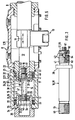
Nachfolgend wird die Erfindung anhand eines in den Fig. 1 bis 4 der Zeichnung dargestellten Ausführungsbeispiels näher erläutert, und zwar bei Anwendung bei der eingangs schon beschriebenen Axialkolbenmaschine 1.
Es zeigen:
- Fig. 1
- eine erfindungsgemäße Justiervorrichtung in einem der Fig. 6 entsprechender Schnitt;
- Fig. 2
- den Einstell-
Gewindebolzen 16 mit dem erfindungsgemäßen Gewindeteil und derKonterschraube 18 in vergrößerter Einzeldarstellung; - Fig. 3
- den
Gewindebolzen 16 gemäß Fig. 2 in der Seitenansicht; - Fig. 4
- den Schnitt IV-IV in Fig. 2.
Show it:
- Fig. 1
- an adjusting device according to the invention in a section corresponding to FIG. 6;
- Fig. 2
- the adjusting threaded
bolt 16 with the threaded part according to the invention and thelock screw 18 in an enlarged individual representation; - Fig. 3
- the threaded
bolt 16 of Figure 2 in side view. - Fig. 4
- the section IV-IV in Fig. 2nd
Bei der erfindungsgemäßen Ausgestaltung ist als Konterglied 51 ein zusätzliches Gewindeteil 55 mit einem Außengewinde und einem Innengewinde vorgesehen, wobei das Außengewinde dem Einstellgewinde 44 des Verstellgliedes 12 und das Innengewinde dem Außengewinde 53 der Konterschraube 18 entspricht und auf letzterer aufgenommen ist. Die Konterschraube 18 erstreckt sich durch eine gewindefreie axiale Durchgangsbohrung 56 im Gewindebolzen 16, und sie weist an ihrem dem Gewindeteil 55 abgewandten Ende einen Schraubenkopf 57 mit einem nicht dargestellten Eingriffselement für ein Konterwerkzeug auf. Es ist eine Ausnehmung 58 im Gewindebolzen 16 unmittelbar hinter dem Angriffsglied 46 des Gewindebolzens 16 zur Aufnahme des Schraubenkopfes 57 vorgesehen, die eine Schulter 59 bildet, an der der Schraubenkopf 57 anliegt. Die Anordnung ist so getroffen, daß die Schraubenspitze das Gewindeteil 55 geringfügig überragt. An diesem überragenden Abschnitt ist ein Anschlag 61 in Form eines die Konterschraube 18 in einem Querloch durchfassenden Stiftes bzw. Spannhülse vorgesehen, wodurch das Gewindeteil 55 unverlierbar an der Konterschraube 18 gehalten ist.In the embodiment according to the invention, an additional threaded
Der Anschlag 61 sichert auch den ständigen Eingriff einer zwischen dem Gewindebolzen 16 und dem Gewindeteil 55 angeordneten Klauenkupplung 62, die eine Verdrehsicherung für das Gewindeteil 55 darstellt und durch eine Quernut 63 in der dem Gewindeteil 55 zugewandten Stirnseite des Gewindebolzens 16 und einen in die Quernut 63 einfassenden Steg 64 auf der dem Gewindebolzen 16 zugewandten Stirnseite des Gewindeteils 55 gebildet ist. Zwischen dem Gewindebolzen 16 und dem Gewindeteil 55 ist ein elastisches Glied 65 in Form eines O-Ringes aus elastischem Kunststoff oder Gummi angeordnet, der das Einschrauben der vom Gewindebolzen 16, der Konterschraube 18 und dem Gewindeteil 55 gebildeten Bauelements erleichtert.The
Zum Verkontern des Gewindebolzens 16 im Verstellglied 12 ist die Konterschraube 18 beim Vorhandensein von Rechtsgewinde im Uhrzeigersinn zu drehen, wodurch das Gewindeteil 55 gegen den Gewindebolzen 16 verspannt wird. Aufgrund ihrer im Vergleich mit der bekannten Ausgestaltung wesentlich größeren Länge 1 der Konterschraube 18 weist diese ein beträchtliches Dehnungsvermögen auf, was die Fixierung bzw. Verkonterung günstig beeinflußt. Es ist deshalb von Vorteil, eine Dehnschraube als Konterschraube 18 zu benutzen.To lock the threaded
Im Bereich der zweiten Justiervorrichtung 52 ist als Weiterbildung der Erfindung die Klemm-Mutter aus zwei Mutterteilen 66, 67 gebildet, die einen Abstand bzw. Spalt zwischen sich aufweisen und durch wenigstens eine, beim vorliegenden Ausführungsbeispiel zwei einander diametral gegenüberliegende Konterschrauben 69 gegeneinander verspannbar sind. Beim vorliegenden Ausführungsbeispiel weist der innere Mutterteil 66 eine Gewindebohrung und der äußere Mutterteil 67 eine Durchgangsbohrung vorzugsweise mit einer außenseitigen Einsenkung für den Kopf der Konterschraube 69 auf, so daß letztere handhabungsfreundlich bedient werden kann. Die wenigstens eine Konterschraube 69 führt auch gleichzeitig zu einer Verdrehsicherung zwischen den Mutterteilen 66,67.In the area of the second adjusting device 52, as a further development of the invention, the clamping nut is formed from two
Claims (13)
- Adjusting device (15) for adjusting a regulating element (12) for a regulating device (8) of an axial or radial piston machine (1) of adjustable throughput volume, with the regulating element (12) being arranged in an adjustable manner in a machine-side guide (22) and having a bore (43) with a setting thread (44), into which a setting thread bolt (16) is screwed with its inner end section (41) which has a setting thread (42), the setting thread bolt being supported in a machine-side support (21,24) such that it cannot be displaced axially and being secured in its respective engagement position with the regulating element (12) by a counter element (51) arranged in the bore (43) and adjacent to the inner end section (41) of the setting thread bolt (16), which counter element can be adjusted relative to the setting thread bolt (16) by means of a counter screw (18) with an external thread and arranged in an axial through-hole in the setting thread bolt (16) and supported axially thereon,
characterized in that
the counter element (51) is constructed as a separate hollow-cylindrical threaded part (55) with an external thread and an internal thread, with which it is located in threaded engagement with an internal thread (44) constructed in the bore (43) in the regulating element (12) or the external thread (53) of the counter screw (18). - Adjusting device according to claim 1,
characterized in that
the internal thread (44), engaged with the external thread of the threaded part (55), in the bore (43) in the regulating element (12) is its setting thread (44). - Adjusting device according to claim 1 or 2,
characterized in that
the counter screw (18) passes through the through-hole (56) in the setting thread bolt (16) and has a screw head (57) which cooperates with a shoulder (59), directed away from the threaded part (55), on the thread bolt (16). - Adjusting device according to claim 3,
characterized in that
the shoulder (59) and the screw head (57) are arranged in the region of the outer end (45) of the thread bolt (16) directed away from the threaded part (55). - Adjusting device according to one of claims 1 to 4,
characterized in that
an anti-rotation element (62) for the threaded part (55) is arranged on the thread bolt (16). - Adjusting device according to claim 5,
characterized in that
the anti-rotation element (62) is formed by a claw coupling (62). - Adjusting device according to claim 6,
characterized in that
the claw coupling (62) is formed by a transverse groove (63) and a bar (64) engaging therein at the sides of the thread bolt (16) and the threaded part (55) which face one another. - Adjusting device according to one of claims 1 to 7,
characterized in that
the threaded part (55) is secured against a downward screwing of the counter screw (18) by a stop (61) on the counter screw (18) preferably in the form of a pin or clamping sleeve engaging through the counter screw (18). - Adjusting device according to claim 8,
characterized in that
with the abutment of the threaded part (55) against the stop (61) the engagement of the claw coupling (62) is ensured. - Adjusting device according to one of claims 1 to 9,
characterized in that
an elastic element (65) working in the axial direction, preferably in the form of an O-ring of rubber or plastics, is arranged between the thread bolt (16) and the threaded part (55). - Adjusting device according to one of claims 1 to 10, with the thread bolt (16) being associated with a two-sided damping device (17) which has two spring plates or pots (24) prestressed by spring force away from one another against shoulders (32, 33), on which plates or pots the thread bolt (16) rests, with an additional setting thread (54) being provided at the outer end (45) of the thread bolt (16), on which setting thread there is screwed a nut (37) which can be secured against unintentional rotation by clamping and which directly or indirectly abuts the outer spring plate (24),
characterized in that
the nut (37) consists of two nut parts (66, 67) having an axial clearance from one another, which parts can be axially braced by at least one counter screw (69) arranged substantially in an axis-parallel manner. - Adjusting device according to claim 11,
characterized in that
the counter screw (69) is screwed into one (66) of the nut parts (66, 67) and is supported at the other nut part (67) in the circumferential direction. - Adjusting device according to claim 12,
characterized in that
the counter screw (69) engages through the outer nut part (67) in a through-hole from the outside and is screwed into the inner nut part (66).
Applications Claiming Priority (2)
| Application Number | Priority Date | Filing Date | Title |
|---|---|---|---|
| DE3800892A DE3800892A1 (en) | 1988-01-14 | 1988-01-14 | ADJUSTMENT DEVICE FOR AN ADJUSTING THREAD BOLT |
| DE3800892 | 1988-01-14 |
Publications (3)
| Publication Number | Publication Date |
|---|---|
| EP0324112A2 EP0324112A2 (en) | 1989-07-19 |
| EP0324112A3 EP0324112A3 (en) | 1990-02-21 |
| EP0324112B1 true EP0324112B1 (en) | 1994-04-06 |
Family
ID=6345273
Family Applications (1)
| Application Number | Title | Priority Date | Filing Date |
|---|---|---|---|
| EP88120649A Expired - Lifetime EP0324112B1 (en) | 1988-01-14 | 1988-12-09 | Adjusting device for a setting bolt |
Country Status (2)
| Country | Link |
|---|---|
| EP (1) | EP0324112B1 (en) |
| DE (2) | DE3800892A1 (en) |
Families Citing this family (2)
| Publication number | Priority date | Publication date | Assignee | Title |
|---|---|---|---|---|
| FI96149C (en) * | 1994-05-25 | 1996-05-10 | Seppo Metsaelae | Fine mechanical control device |
| DE69734684T2 (en) * | 1997-12-16 | 2006-08-10 | Seppo Metsälä | FEINMECHANICAL CROSS-POSITIONING DEVICE |
Family Cites Families (10)
| Publication number | Priority date | Publication date | Assignee | Title |
|---|---|---|---|---|
| FR2079E (en) * | 1903-12-26 | Andre Minne | New system of so-called rational locknut | |
| DE800512C (en) * | 1948-10-02 | 1950-11-13 | Paul Steinmetzer | Nut lock |
| US2998733A (en) * | 1959-06-02 | 1961-09-05 | Kenneth W Thompson | Control device |
| DE1453657B2 (en) * | 1964-07-17 | 1972-07-06 | Brüninghaus Hydraulik GmbH, 7240 Horb | ADJUSTMENT DEVICE, IN PARTICULAR FOR AXIAL PISTON MACHINES |
| JPS5694019A (en) * | 1979-12-26 | 1981-07-30 | Masao Kanazawa | Lock bolt |
| US4466261A (en) * | 1980-10-20 | 1984-08-21 | Zimmer John C | Security apparatus |
| DE3413444C2 (en) * | 1984-04-10 | 1986-03-27 | Robert Bosch Gmbh, 7000 Stuttgart | Safety and display device against unauthorized adjustment of a screw |
| FR2566483B1 (en) * | 1984-06-21 | 1991-10-04 | Cuilleron J | DOUBLE-ACTING NUT FOR ADJUSTING AND RETRIEVING GAMES IN THREADED MECHANICAL ASSEMBLIES |
| DE3433738A1 (en) * | 1984-09-14 | 1986-03-20 | Fa. Carl Zeiss, 7920 Heidenheim | DEVICE FOR LOCAL FIXING OF A THREADED BOLT |
| CH666093A5 (en) * | 1985-05-30 | 1988-06-30 | Sulzer Ag | SCREW CONNECTION. |
-
1988
- 1988-01-14 DE DE3800892A patent/DE3800892A1/en not_active Ceased
- 1988-12-09 EP EP88120649A patent/EP0324112B1/en not_active Expired - Lifetime
- 1988-12-09 DE DE88120649T patent/DE3888956D1/en not_active Expired - Fee Related
Also Published As
| Publication number | Publication date |
|---|---|
| DE3800892A1 (en) | 1989-07-27 |
| DE3888956D1 (en) | 1994-05-11 |
| EP0324112A2 (en) | 1989-07-19 |
| EP0324112A3 (en) | 1990-02-21 |
Similar Documents
| Publication | Publication Date | Title |
|---|---|---|
| DE2339873C2 (en) | Arrangement for setting and securing a block carrying a cutting tip in a groove-shaped receptacle in the tool body of a cutting tool | |
| DE3610284C2 (en) | ||
| EP0039765B1 (en) | Device for mounting flexible printing plates on the plate cylinder of rotary printing presses | |
| DE3929802C1 (en) | ||
| DE102007030876B4 (en) | Tool for chip-removing machining of workpieces | |
| EP0962280B1 (en) | Alignment device | |
| DE68914680T2 (en) | TOOL HOLDER WITH CLAMPING MECHANISM WITH BUILT-IN BLOCKING WEDGE. | |
| DE2141366A1 (en) | Tool for assembling or disassembling coil spring shock absorbers and procedures using this tool | |
| DE3928876C2 (en) | Device for adjusting a bumper on a motor vehicle | |
| DE3029133C2 (en) | Tool holder | |
| DE8627319U1 (en) | Segment for aligning a mold plate on a machine tool table | |
| DE2953815C2 (en) | Blanket tensioner | |
| EP0324112A2 (en) | Adjusting device for a setting bolt | |
| EP0308645B1 (en) | Orthodontic expander | |
| DE2158779A1 (en) | Adjustable machine reamer | |
| EP0598165A1 (en) | Device for rotatable assembling of parts, for instance heald rods, heald drivers and looms with such device | |
| WO2009080002A1 (en) | Fine adjusting device with threaded spindle | |
| DE4407270C1 (en) | Cutting-tip adjusting device | |
| DE19750614C2 (en) | Device for changing the displacement volume of a hydrostatic machine | |
| DE20106561U1 (en) | Device for connecting profile bars | |
| EP1134440B1 (en) | Connection assembly | |
| AT387823B (en) | Auxiliary device for an actuating rod of the regulating members provided on pump/nozzle assemblies of fuel- injection internal combustion engines | |
| EP0255706B1 (en) | Adjusting device of the relative position of construction elements, particularly tensioning device for transmission with endless flexible member | |
| DE3009288A1 (en) | TWO-CIRCUIT PRESSURE REGULATOR | |
| EP2562460B1 (en) | Dispositif de réglage |
Legal Events
| Date | Code | Title | Description |
|---|---|---|---|
| PUAI | Public reference made under article 153(3) epc to a published international application that has entered the european phase |
Free format text: ORIGINAL CODE: 0009012 |
|
| AK | Designated contracting states |
Kind code of ref document: A2 Designated state(s): DE GB IT SE |
|
| PUAL | Search report despatched |
Free format text: ORIGINAL CODE: 0009013 |
|
| AK | Designated contracting states |
Kind code of ref document: A3 Designated state(s): DE GB IT SE |
|
| 17P | Request for examination filed |
Effective date: 19900307 |
|
| 17Q | First examination report despatched |
Effective date: 19920909 |
|
| GRAA | (expected) grant |
Free format text: ORIGINAL CODE: 0009210 |
|
| AK | Designated contracting states |
Kind code of ref document: B1 Designated state(s): DE GB IT SE |
|
| REF | Corresponds to: |
Ref document number: 3888956 Country of ref document: DE Date of ref document: 19940511 |
|
| ITF | It: translation for a ep patent filed | ||
| GBT | Gb: translation of ep patent filed (gb section 77(6)(a)/1977) |
Effective date: 19940712 |
|
| EAL | Se: european patent in force in sweden |
Ref document number: 88120649.4 |
|
| PLBE | No opposition filed within time limit |
Free format text: ORIGINAL CODE: 0009261 |
|
| STAA | Information on the status of an ep patent application or granted ep patent |
Free format text: STATUS: NO OPPOSITION FILED WITHIN TIME LIMIT |
|
| 26N | No opposition filed | ||
| REG | Reference to a national code |
Ref country code: GB Ref legal event code: IF02 |
|
| PGFP | Annual fee paid to national office [announced via postgrant information from national office to epo] |
Ref country code: SE Payment date: 20061213 Year of fee payment: 19 |
|
| PGFP | Annual fee paid to national office [announced via postgrant information from national office to epo] |
Ref country code: DE Payment date: 20061218 Year of fee payment: 19 |
|
| PGFP | Annual fee paid to national office [announced via postgrant information from national office to epo] |
Ref country code: GB Payment date: 20061221 Year of fee payment: 19 |
|
| PGFP | Annual fee paid to national office [announced via postgrant information from national office to epo] |
Ref country code: IT Payment date: 20061231 Year of fee payment: 19 |
|
| EUG | Se: european patent has lapsed | ||
| GBPC | Gb: european patent ceased through non-payment of renewal fee |
Effective date: 20071209 |
|
| PG25 | Lapsed in a contracting state [announced via postgrant information from national office to epo] |
Ref country code: DE Free format text: LAPSE BECAUSE OF NON-PAYMENT OF DUE FEES Effective date: 20080701 Ref country code: SE Free format text: LAPSE BECAUSE OF NON-PAYMENT OF DUE FEES Effective date: 20071210 |
|
| PG25 | Lapsed in a contracting state [announced via postgrant information from national office to epo] |
Ref country code: GB Free format text: LAPSE BECAUSE OF NON-PAYMENT OF DUE FEES Effective date: 20071209 |
|
| PG25 | Lapsed in a contracting state [announced via postgrant information from national office to epo] |
Ref country code: IT Free format text: LAPSE BECAUSE OF NON-PAYMENT OF DUE FEES Effective date: 20071209 |