EP0324183A1 - Mehretagige einstückige Tragevorrichtung zur Wärmebehandlung von Wellen und Achsen - Google Patents
Mehretagige einstückige Tragevorrichtung zur Wärmebehandlung von Wellen und Achsen Download PDFInfo
- Publication number
- EP0324183A1 EP0324183A1 EP88121890A EP88121890A EP0324183A1 EP 0324183 A1 EP0324183 A1 EP 0324183A1 EP 88121890 A EP88121890 A EP 88121890A EP 88121890 A EP88121890 A EP 88121890A EP 0324183 A1 EP0324183 A1 EP 0324183A1
- Authority
- EP
- European Patent Office
- Prior art keywords
- parts
- orifices
- ribs
- support
- shafts
- Prior art date
- Legal status (The legal status is an assumption and is not a legal conclusion. Google has not performed a legal analysis and makes no representation as to the accuracy of the status listed.)
- Granted
Links
- 238000007669 thermal treatment Methods 0.000 title abstract 2
- 239000012530 fluid Substances 0.000 claims abstract description 4
- 238000010438 heat treatment Methods 0.000 claims description 7
- 230000000712 assembly Effects 0.000 description 5
- 238000000429 assembly Methods 0.000 description 5
- 230000035939 shock Effects 0.000 description 4
- 125000006850 spacer group Chemical group 0.000 description 3
- 239000012634 fragment Substances 0.000 description 2
- 239000000956 alloy Substances 0.000 description 1
- 229910045601 alloy Inorganic materials 0.000 description 1
- 238000001816 cooling Methods 0.000 description 1
- 239000012809 cooling fluid Substances 0.000 description 1
- 230000001627 detrimental effect Effects 0.000 description 1
- 238000009432 framing Methods 0.000 description 1
- 239000011229 interlayer Substances 0.000 description 1
- 238000012423 maintenance Methods 0.000 description 1
- 238000010791 quenching Methods 0.000 description 1
- 230000000171 quenching effect Effects 0.000 description 1
Images


Classifications
-
- C—CHEMISTRY; METALLURGY
- C21—METALLURGY OF IRON
- C21D—MODIFYING THE PHYSICAL STRUCTURE OF FERROUS METALS; GENERAL DEVICES FOR HEAT TREATMENT OF FERROUS OR NON-FERROUS METALS OR ALLOYS; MAKING METAL MALLEABLE, e.g. BY DECARBURISATION OR TEMPERING
- C21D9/00—Heat treatment, e.g. annealing, hardening, quenching or tempering, adapted for particular articles; Furnaces therefor
- C21D9/0006—Details, accessories not peculiar to any of the following furnaces
- C21D9/0025—Supports; Baskets; Containers; Covers
-
- F—MECHANICAL ENGINEERING; LIGHTING; HEATING; WEAPONS; BLASTING
- F27—FURNACES; KILNS; OVENS; RETORTS
- F27D—DETAILS OR ACCESSORIES OF FURNACES, KILNS, OVENS OR RETORTS, IN SO FAR AS THEY ARE OF KINDS OCCURRING IN MORE THAN ONE KIND OF FURNACE
- F27D5/00—Supports, screens or the like for the charge within the furnace
- F27D5/005—Supports specially adapted for holding elongated articles in an upright position, e.g. sparking plugs
Definitions
- the invention relates to support and handling assemblies for heat treatment in groups of mechanical parts such as shafts or axes.
- the most commonly used heat treatment assemblies are of two types: a first type where the parts are placed and guided, and a second type where the parts are suspended.
- the assemblies of the first type consist of a base plate for handling comprising columns on which are mounted a lower grid and an upper grid separated by tubular spacers surrounding the columns, each part being supported by a support interlayer being mounted in one of the housings of the lower grid, and guided at its upper part by a guide insert being mounted in a similar orifice of the upper grid.
- the second type assemblies include the same elements as those of the first type, except the lower grid and the guide spacers, the support spacers being of a special type and mounted in the upper grid.
- the object of the invention is to eliminate the above drawbacks, that is to say to produce an assembly which, like the previous ones, ensures the vertical positioning of the parts to avoid deformations during processing, but which is entirely at the same time as light as possible while grouping the maximum number of parts in order to maximize the payload as well as the number of parts to be treated per load, which favors the cooling conditions during quenching by good passage of fluids, which is highly resistant to thermal shock and to the thrust forces of a pushing furnace, and which finally allows the positioning of the parts in a simple manner that can easily be automated.
- the invention consists in making an assembly for the heat treatment of trees or axes in a vertical position comprising a monobloc assembly in the form of a plate which combines both an upper stage formed of support orifices, possibly on several alternating levels, for direct support and centering of the lower end of the parts, these orifices being joined by horizontal ribs, a lower stage also formed of orifices and ribs, and vertical pillars joining these ribs from one and the other stage, while leaving large openings for the circulation of fluids .
- the parts 1 to be treated are assumed to be gearbox shafts 2 comprising several pinions 3 formed in one piece with the shaft 2, this type of part being particularly difficult to treat.
- the invention would apply a fortiori to elongated parts of simpler shape and less bulky.
- the single assembly 4 in the form of a two-stage tray 5 and 6.
- the upper stage 5 comprises a number of orifices 7 each surrounded by a tubular sleeve 8, these various sleeves 8 and orifices 7 being arranged in a two-dimensional network and joined together by ribs 9 in at least two directions.
- Each orifice 7 is intended to receive a cylindrical lower part 10 of one of the parts 1 which is supported by a conical or planar part on the upper edge of the corresponding sleeve 8.
- the lower stage 6 also consists of orifices 11 surrounded by cylindrical sleeves 12 themselves joined by ribs 13, preferably also in the two directions. Special framing ribs 9a surround the entire upper stage 5, and in the same way special ribs 13a surround the entire lower stage 6.
- a series of vertical pillars 14 join two by two of the ribs such as 9 or 9a of the upper stage and ribs such as 13 or 13a of the lower stage.
- all these ribs and these pillars allow large openings 15 to exist between them, serving both to ensure the free circulation of the heating and then cooling fluid, and at the same time to lighten the part while retaining high resistance.
- the whole of the plate 4 is made in one piece, which can be easily obtained for example in foundry using an alloy with high resistance to thermal shock.
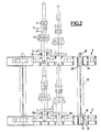
- the holes 7 and the sleeves 8 of the upper plate are arranged on two alternating levels, such as 8a and 8b, in order to avoid, as seen in Figures 2 and 3 , the interference between the gears 3 of larger diameter in order to reduce the center distance of the orifices 7 and consequently increase the load per plate.
- the assembly is relatively simple and light, especially with regard to the weight of supported parts, while improving the quality of the parts by an excellent resistance which prevents the shocks of the parts between them during treatment and during loading.
- the loading of the parts is done in an extremely simple manner, since it suffices to bring each part in front of the corresponding orifice 7 and to introduce it there by simple vertical axial translation, which is easily achievable by a manipulator arm.
- the weight of supported parts can be relatively high, especially with the second embodiment.
- the invention makes it possible, if desired, to superimpose two or more similar trays for simultaneous heat treatment, by stacking these trays, once loaded with their parts, on top of each other by means of stepped columns such as shown at 16 in FIG. 2, each of these columns having for example an X section with a cylindrical lower end 17 with base 18 and an upper end 19 which can also be X section and include a stop base 20.
- the ends 17 and 19 can be mounted in additional holes provided for this purpose, for example in the corners of each plate 4. This latter arrangement further improves the density of the load, therefore the productivity of the treatment.
Landscapes
- Engineering & Computer Science (AREA)
- Chemical & Material Sciences (AREA)
- Mechanical Engineering (AREA)
- Crystallography & Structural Chemistry (AREA)
- Thermal Sciences (AREA)
- Physics & Mathematics (AREA)
- General Engineering & Computer Science (AREA)
- Materials Engineering (AREA)
- Metallurgy (AREA)
- Organic Chemistry (AREA)
- Heat Treatments In General, Especially Conveying And Cooling (AREA)
- Furnace Charging Or Discharging (AREA)
- Tunnel Furnaces (AREA)
- Heat Treatment Of Articles (AREA)
- Heating, Cooling, Or Curing Plastics Or The Like In General (AREA)
Priority Applications (1)
| Application Number | Priority Date | Filing Date | Title |
|---|---|---|---|
| AT88121890T ATE87089T1 (de) | 1988-01-15 | 1988-12-30 | Mehretagige einstueckige tragevorrichtung zur waermebehandlung von wellen und achsen. |
Applications Claiming Priority (2)
| Application Number | Priority Date | Filing Date | Title |
|---|---|---|---|
| FR8800451 | 1988-01-15 | ||
| FR8800451A FR2626068B1 (fr) | 1988-01-15 | 1988-01-15 | Montage monobloc a plateaux etages pour traitement thermique d'arbres ou d'axes |
Publications (2)
| Publication Number | Publication Date |
|---|---|
| EP0324183A1 true EP0324183A1 (de) | 1989-07-19 |
| EP0324183B1 EP0324183B1 (de) | 1993-03-17 |
Family
ID=9362362
Family Applications (1)
| Application Number | Title | Priority Date | Filing Date |
|---|---|---|---|
| EP88121890A Expired - Lifetime EP0324183B1 (de) | 1988-01-15 | 1988-12-30 | Mehretagige einstückige Tragevorrichtung zur Wärmebehandlung von Wellen und Achsen |
Country Status (9)
| Country | Link |
|---|---|
| US (1) | US4978109A (de) |
| EP (1) | EP0324183B1 (de) |
| JP (1) | JPH01287219A (de) |
| AT (1) | ATE87089T1 (de) |
| CA (1) | CA1327815C (de) |
| DE (1) | DE3879454T2 (de) |
| ES (1) | ES2038737T3 (de) |
| FR (1) | FR2626068B1 (de) |
| PT (1) | PT89429B (de) |
Cited By (3)
| Publication number | Priority date | Publication date | Assignee | Title |
|---|---|---|---|---|
| FR2772467A1 (fr) * | 1997-12-15 | 1999-06-18 | Snecma | Dispositif de chargement pour le support de pieces a traiter thermiquement dans un four |
| CN102483306A (zh) * | 2009-08-14 | 2012-05-30 | Gtd石墨技术股份有限公司 | 改进的工件输送架 |
| CN105349740A (zh) * | 2015-11-15 | 2016-02-24 | 岳文智 | 一种金属管加工用淬火架 |
Families Citing this family (15)
| Publication number | Priority date | Publication date | Assignee | Title |
|---|---|---|---|---|
| DE4016172C1 (de) * | 1990-05-19 | 1991-03-28 | Werner 5900 Siegen De Ackermann | |
| DE29608569U1 (de) * | 1996-05-13 | 1996-08-14 | Karl Heess GmbH & Co Maschinenbau, 68623 Lampertheim | Vorrichtung zum Aufnehmen und Umsetzen von Wärmebehandlungsschritten zu unterwerfenden Werkstücken |
| US5752821A (en) * | 1996-07-02 | 1998-05-19 | Kia Motors Corporation | Tray for heat treatment furnace |
| DE19957906A1 (de) * | 1999-12-01 | 2001-06-28 | Schunk Kohlenstofftechnik Gmbh | Verfahren zur Herstellung eines Faserverbund-Bauteils sowie Vorrichtung zur Herstellung eines solchen |
| DE10109565B4 (de) * | 2001-02-28 | 2005-10-20 | Vacuheat Gmbh | Verfahren und Vorrichtung zur partiellen thermochemischen Vakuumbehandlung von metallischen Werkstücken |
| WO2002097141A1 (en) | 2001-05-29 | 2002-12-05 | Demmer Corporation | Heat treatment container |
| CN1322148C (zh) * | 2004-12-16 | 2007-06-20 | 上海汽车股份有限公司 | 高压气体淬火料架 |
| DE102005001440A1 (de) * | 2005-01-09 | 2006-07-20 | Wolfgang Meinus | Mehretagige Tragevorrichtung zur Wärmebehandlung von Wellen und Achsen durch Zentrierung von Oberrost (Halterost) und Unterrost (Aufnahmerost) mittels Kegel- und/oder Pyramidenverbindung, auch in Streifen |
| CN102080144B (zh) * | 2010-11-29 | 2012-08-08 | 苏州中门子科技有限公司 | 模块式抗变形炉底板 |
| KR101366704B1 (ko) | 2012-06-22 | 2014-02-25 | (주)수산서비스 | 브레이커의 부품 열처리용 바스켓 |
| JP6697902B2 (ja) * | 2016-02-26 | 2020-05-27 | 株式会社三井ハイテック | トレイ及び熱処理方法 |
| MX2020012473A (es) * | 2018-08-21 | 2021-04-28 | Nikko Kinzoku Co Ltd | Miembro de bandeja de tratamiento termico y estructura apilada de tratamiento termico. |
| CN109366394A (zh) * | 2018-12-05 | 2019-02-22 | 盐城远大金属科技有限公司 | 一种带孔轴类工装 |
| MX2021013795A (es) * | 2020-02-26 | 2021-12-10 | Nikko Kinzoku Co Ltd | Miembro de tratamiento termico y estructura de tratamiento termico. |
| CN112359197A (zh) * | 2020-11-10 | 2021-02-12 | 中冶陕压重工设备有限公司 | 一种用于大型热处理燃气炉的托盘 |
Citations (3)
| Publication number | Priority date | Publication date | Assignee | Title |
|---|---|---|---|---|
| GB190904370A (en) * | 1909-02-22 | 1909-10-07 | Frank Dransfield | An Improved Device for use in the Manufacture of Earthenware Pipes and the like. |
| DE2542083B1 (de) * | 1975-07-30 | 1976-03-25 | Deere & Co | Transportbehaelter aus hitzebestaendigem Stahl fuer zu haertende Artikel |
| US4572749A (en) * | 1984-03-07 | 1986-02-25 | Gkn Automotive Components, Inc. | Method and an apparatus for heat treatment of a workpiece |
Family Cites Families (9)
| Publication number | Priority date | Publication date | Assignee | Title |
|---|---|---|---|---|
| US2179073A (en) * | 1935-06-10 | 1939-11-07 | Timken Axle Co Detroit | Apparatus for heat treating |
| US2137737A (en) * | 1937-04-13 | 1938-11-22 | Albert W Wenzel | Packing ring holding apparatus |
| US2300783A (en) * | 1940-11-16 | 1942-11-03 | Wright Aeronautical Corp | Furnace charging fixture |
| US2369756A (en) * | 1941-12-20 | 1945-02-20 | American Steel & Wire Co | Base for metallurgical furnaces and the like |
| SU389154A1 (de) * | 1971-04-05 | 1973-07-05 | ||
| JPS5078332A (de) * | 1973-11-08 | 1975-06-26 | ||
| US4212690A (en) * | 1979-03-23 | 1980-07-15 | Nasa | Heat treat fixture and method of heat treating |
| JPS636194U (de) * | 1986-07-01 | 1988-01-16 | ||
| US4815971A (en) * | 1987-11-27 | 1989-03-28 | Westinghouse Electric Corp. | Multi-tier load fixture for a top-loading furnace furnace |
-
1988
- 1988-01-15 FR FR8800451A patent/FR2626068B1/fr not_active Expired - Lifetime
- 1988-12-15 US US07/284,549 patent/US4978109A/en not_active Expired - Fee Related
- 1988-12-30 ES ES198888121890T patent/ES2038737T3/es not_active Expired - Lifetime
- 1988-12-30 DE DE8888121890T patent/DE3879454T2/de not_active Expired - Fee Related
- 1988-12-30 AT AT88121890T patent/ATE87089T1/de active
- 1988-12-30 EP EP88121890A patent/EP0324183B1/de not_active Expired - Lifetime
-
1989
- 1989-01-11 CA CA000587967A patent/CA1327815C/fr not_active Expired - Fee Related
- 1989-01-12 PT PT89429A patent/PT89429B/pt not_active IP Right Cessation
- 1989-01-13 JP JP1007539A patent/JPH01287219A/ja active Pending
Patent Citations (3)
| Publication number | Priority date | Publication date | Assignee | Title |
|---|---|---|---|---|
| GB190904370A (en) * | 1909-02-22 | 1909-10-07 | Frank Dransfield | An Improved Device for use in the Manufacture of Earthenware Pipes and the like. |
| DE2542083B1 (de) * | 1975-07-30 | 1976-03-25 | Deere & Co | Transportbehaelter aus hitzebestaendigem Stahl fuer zu haertende Artikel |
| US4572749A (en) * | 1984-03-07 | 1986-02-25 | Gkn Automotive Components, Inc. | Method and an apparatus for heat treatment of a workpiece |
Cited By (6)
| Publication number | Priority date | Publication date | Assignee | Title |
|---|---|---|---|---|
| FR2772467A1 (fr) * | 1997-12-15 | 1999-06-18 | Snecma | Dispositif de chargement pour le support de pieces a traiter thermiquement dans un four |
| WO1999031284A1 (fr) * | 1997-12-15 | 1999-06-24 | Societe Nationale D'etude Et De Construction De Moteurs D'aviation - Snecma | Dispositif de chargement pour le support de pieces a traiter thermiquement dans un four |
| US6318571B1 (en) | 1997-12-15 | 2001-11-20 | Societe Nationale D'etude Et De Construction De Moteurs D'aviation - S.N.E.C.M.A. | Loader device for supporting parts for heat treatment in a furnace |
| RU2220394C2 (ru) * | 1997-12-15 | 2003-12-27 | Сосьете Насьональ Д'Этюд Э Де Констрюксьон Де Мотер Д'Авиасьон - Снекма | Устройство загрузки для удержания деталей, подлежащих термической обработке в печи |
| CN102483306A (zh) * | 2009-08-14 | 2012-05-30 | Gtd石墨技术股份有限公司 | 改进的工件输送架 |
| CN105349740A (zh) * | 2015-11-15 | 2016-02-24 | 岳文智 | 一种金属管加工用淬火架 |
Also Published As
| Publication number | Publication date |
|---|---|
| ATE87089T1 (de) | 1993-04-15 |
| DE3879454T2 (de) | 1993-09-09 |
| ES2038737T3 (es) | 1993-08-01 |
| CA1327815C (fr) | 1994-03-15 |
| PT89429B (pt) | 1994-01-31 |
| PT89429A (pt) | 1989-10-04 |
| US4978109A (en) | 1990-12-18 |
| DE3879454D1 (de) | 1993-04-22 |
| FR2626068B1 (fr) | 1990-06-29 |
| FR2626068A1 (fr) | 1989-07-21 |
| EP0324183B1 (de) | 1993-03-17 |
| JPH01287219A (ja) | 1989-11-17 |
Similar Documents
| Publication | Publication Date | Title |
|---|---|---|
| EP0324183B1 (de) | Mehretagige einstückige Tragevorrichtung zur Wärmebehandlung von Wellen und Achsen | |
| EP0468870B1 (de) | Kernreaktor-Brennstabbündel mit zusätzlichem Abstandshalter | |
| EP1817776B1 (de) | Anlage zum zusammenschweissen von skeletten für kernbrennstabbündel, verfahren zu deren programmierung, verfahren zum zusammenschweissen von skeletten und zur fertigung von mit denselben ausgerüsteten kernbrennstabbündeln | |
| BE897637A (fr) | Dispositif et procede de positionnement de lames et d'ailettes pour des grilles de support de barres de combustible nucleaire | |
| EP1042517B1 (de) | Anordnung zur ladung von gutträgern für thermische ofenbehandlungen | |
| EP0858079B1 (de) | Lagergestell für Kernreaktorbrennstabbündel mit durch Rahmen festgehaltenen Neutronenabsorberelementen | |
| EP0612869A1 (de) | Trägerkassette für Siliziumscheiben | |
| FR2633436A1 (fr) | Procede et element de maintien pour la reparation d'un assemblage combustible nucleaire, endommage en peripherie d'un support entretoise | |
| EP0477097A1 (de) | Führungseinrichtung für das Kontrollbündel eines Kernreaktors | |
| FR2744556A1 (fr) | Assemblage de combustible nucleaire comportant un embout superieur ameliore | |
| FR2680909A1 (fr) | Ratelier de stockage ou de transport de combustible nucleaire et son procede de fabrication. | |
| EP0088363B1 (de) | Vorrichtung zur Aufhängung von Rohrbündeln | |
| FR2674465A1 (fr) | Procede pour souder deux pieces, notamment un composant electrique, et/ou une plaquette semi-conducteur. | |
| BE897638A (fr) | Dispositif bande de retenue et procede pour l'aqssemblage de grille de support de barres de combustible nucleaire | |
| FR2742912A1 (fr) | Grappe de commande pour reacteur nucleaire, a crayons demontables | |
| EP0349379B1 (de) | Regelspinne mit demortierbaren Stäben für ein Kernbrennstabbündel | |
| JP2006057126A (ja) | 熱処理治具 | |
| EP0323306B1 (de) | Druckwasserkernreaktor mit massiver Kernumfassung | |
| FR3099561A1 (fr) | Dispositif modulaire pour positionner des pièces métalliques lors d’opérations de traitement thermique. | |
| FR2693825A1 (fr) | Assemblage combustible nucléaire et ensemble grappe-assemblage en comportant application. | |
| FR2719615A1 (fr) | Procédé d'assemblage de tronçons de grande longueur de membrures des jambes de support d'une plate-forme pétrolière. | |
| EP4048965A1 (de) | Gaslöschzelle | |
| FR2599178A1 (fr) | Embout superieur pour assemblages combustibles dans un reacteur nucleaire | |
| FR3132037A1 (fr) | Procede de fabrication d’une piece de forme complexe | |
| FR3128142A1 (fr) | Système de montage pour l’usinage de pièces et procédé d’usinage associé |
Legal Events
| Date | Code | Title | Description |
|---|---|---|---|
| PUAI | Public reference made under article 153(3) epc to a published international application that has entered the european phase |
Free format text: ORIGINAL CODE: 0009012 |
|
| AK | Designated contracting states |
Kind code of ref document: A1 Designated state(s): AT BE DE ES GB IT NL SE |
|
| 17P | Request for examination filed |
Effective date: 19890725 |
|
| 17Q | First examination report despatched |
Effective date: 19910502 |
|
| ITF | It: translation for a ep patent filed | ||
| GRAA | (expected) grant |
Free format text: ORIGINAL CODE: 0009210 |
|
| AK | Designated contracting states |
Kind code of ref document: B1 Designated state(s): AT BE DE ES GB IT NL SE |
|
| REF | Corresponds to: |
Ref document number: 87089 Country of ref document: AT Date of ref document: 19930415 Kind code of ref document: T |
|
| REF | Corresponds to: |
Ref document number: 3879454 Country of ref document: DE Date of ref document: 19930422 |
|
| GBT | Gb: translation of ep patent filed (gb section 77(6)(a)/1977) |
Effective date: 19930331 |
|
| REG | Reference to a national code |
Ref country code: ES Ref legal event code: FG2A Ref document number: 2038737 Country of ref document: ES Kind code of ref document: T3 |
|
| PLBE | No opposition filed within time limit |
Free format text: ORIGINAL CODE: 0009261 |
|
| STAA | Information on the status of an ep patent application or granted ep patent |
Free format text: STATUS: NO OPPOSITION FILED WITHIN TIME LIMIT |
|
| 26N | No opposition filed | ||
| EAL | Se: european patent in force in sweden |
Ref document number: 88121890.3 |
|
| PGFP | Annual fee paid to national office [announced via postgrant information from national office to epo] |
Ref country code: GB Payment date: 19991026 Year of fee payment: 12 |
|
| PGFP | Annual fee paid to national office [announced via postgrant information from national office to epo] |
Ref country code: SE Payment date: 19991108 Year of fee payment: 12 |
|
| PGFP | Annual fee paid to national office [announced via postgrant information from national office to epo] |
Ref country code: ES Payment date: 19991207 Year of fee payment: 12 |
|
| PGFP | Annual fee paid to national office [announced via postgrant information from national office to epo] |
Ref country code: BE Payment date: 19991215 Year of fee payment: 12 |
|
| PGFP | Annual fee paid to national office [announced via postgrant information from national office to epo] |
Ref country code: AT Payment date: 19991227 Year of fee payment: 12 |
|
| PGFP | Annual fee paid to national office [announced via postgrant information from national office to epo] |
Ref country code: DE Payment date: 19991228 Year of fee payment: 12 |
|
| PGFP | Annual fee paid to national office [announced via postgrant information from national office to epo] |
Ref country code: NL Payment date: 19991231 Year of fee payment: 12 |
|
| PG25 | Lapsed in a contracting state [announced via postgrant information from national office to epo] |
Ref country code: GB Free format text: LAPSE BECAUSE OF NON-PAYMENT OF DUE FEES Effective date: 20001230 Ref country code: AT Free format text: LAPSE BECAUSE OF NON-PAYMENT OF DUE FEES Effective date: 20001230 |
|
| PG25 | Lapsed in a contracting state [announced via postgrant information from national office to epo] |
Ref country code: SE Free format text: LAPSE BECAUSE OF NON-PAYMENT OF DUE FEES Effective date: 20001231 Ref country code: BE Free format text: LAPSE BECAUSE OF NON-PAYMENT OF DUE FEES Effective date: 20001231 |
|
| BERE | Be: lapsed |
Owner name: SOC. MANCELLE DE FONDERIE Effective date: 20001231 |
|
| PG25 | Lapsed in a contracting state [announced via postgrant information from national office to epo] |
Ref country code: NL Free format text: LAPSE BECAUSE OF NON-PAYMENT OF DUE FEES Effective date: 20010701 |
|
| EUG | Se: european patent has lapsed |
Ref document number: 88121890.3 |
|
| GBPC | Gb: european patent ceased through non-payment of renewal fee |
Effective date: 20001230 |
|
| NLV4 | Nl: lapsed or anulled due to non-payment of the annual fee |
Effective date: 20010701 |
|
| PG25 | Lapsed in a contracting state [announced via postgrant information from national office to epo] |
Ref country code: DE Free format text: LAPSE BECAUSE OF NON-PAYMENT OF DUE FEES Effective date: 20011002 |
|
| PG25 | Lapsed in a contracting state [announced via postgrant information from national office to epo] |
Ref country code: ES Free format text: LAPSE BECAUSE OF NON-PAYMENT OF DUE FEES Effective date: 20011231 |
|
| REG | Reference to a national code |
Ref country code: ES Ref legal event code: FD2A Effective date: 20020112 |
|
| PG25 | Lapsed in a contracting state [announced via postgrant information from national office to epo] |
Ref country code: IT Free format text: LAPSE BECAUSE OF NON-PAYMENT OF DUE FEES;WARNING: LAPSES OF ITALIAN PATENTS WITH EFFECTIVE DATE BEFORE 2007 MAY HAVE OCCURRED AT ANY TIME BEFORE 2007. THE CORRECT EFFECTIVE DATE MAY BE DIFFERENT FROM THE ONE RECORDED. Effective date: 20051230 |