EP0324332A2 - Dispositif de graissage de boulons de chaîne - Google Patents
Dispositif de graissage de boulons de chaîne Download PDFInfo
- Publication number
- EP0324332A2 EP0324332A2 EP88890319A EP88890319A EP0324332A2 EP 0324332 A2 EP0324332 A2 EP 0324332A2 EP 88890319 A EP88890319 A EP 88890319A EP 88890319 A EP88890319 A EP 88890319A EP 0324332 A2 EP0324332 A2 EP 0324332A2
- Authority
- EP
- European Patent Office
- Prior art keywords
- lubrication
- lubricating
- carriage
- chain
- head
- Prior art date
- Legal status (The legal status is an assumption and is not a legal conclusion. Google has not performed a legal analysis and makes no representation as to the accuracy of the status listed.)
- Granted
Links
Images



Classifications
-
- F—MECHANICAL ENGINEERING; LIGHTING; HEATING; WEAPONS; BLASTING
- F16—ENGINEERING ELEMENTS AND UNITS; GENERAL MEASURES FOR PRODUCING AND MAINTAINING EFFECTIVE FUNCTIONING OF MACHINES OR INSTALLATIONS; THERMAL INSULATION IN GENERAL
- F16N—LUBRICATING
- F16N11/00—Arrangements for supplying grease from a stationary reservoir or the equivalent in or on the machine or member to be lubricated; Grease cups
-
- F—MECHANICAL ENGINEERING; LIGHTING; HEATING; WEAPONS; BLASTING
- F16—ENGINEERING ELEMENTS AND UNITS; GENERAL MEASURES FOR PRODUCING AND MAINTAINING EFFECTIVE FUNCTIONING OF MACHINES OR INSTALLATIONS; THERMAL INSULATION IN GENERAL
- F16N—LUBRICATING
- F16N2210/00—Applications
- F16N2210/24—Conveyors
Definitions
- the invention relates to a device for lubricating itself with its z.
- the lubricating head can be adjusted to the lubrication points and reset again via a drive device, at least one position sensor for the lubrication points in their position clearly assigned parts of the rollers or chain pins and a control device are provided, which controls the setting or resetting of the lubricating head and the actuation of the grease gun in predetermined relative positions of the lubricating points to the lubricating device.
- Devices of this type are intended to permit extensive automation of the lubrication of the parts mentioned.
- lubrication not only has the task of reducing friction, it is also intended to protect the sliding parts of the chain and pin against the penetration of aggressive media. It is therefore desirable to provide frequent lubrication and only to compensate for the loss of lubricant that has occurred during a chain circulation.
- the speed of travel with grinder chains is in the order of 1 to 10 m / h.
- a single, from the side, that is to say transversely to the line of movement of the chain bolts or the like supplied chain pin comes into engagement and actuates a pneumatic valve either directly or via assigned electrical switches, which turns on the lubricating head and actuates a grease gun connected to the lubricating head.
- the lubricating head is connected to a pneumatic cylinder by means of a cardanic joint and additionally supported on a roller, in particular a diaboloidal roller, it is turned on and off via the pneumatic cylinder, with an additional control device actuating a valve located in a lubricant line, so that at the Dosed lubricant is dispensed at the lubrication point.
- the gimbal support of the lubrication head is provided in order to compensate for deviations in position of the lubrication point from a desired point. It is necessary to work with very short lubrication cycles, because each lubrication point is only in the target area of the lubrication head for a short time despite the slow adjustment of the chain. Adjustment inaccuracies and the need to adjust the lubrication head very quickly under high pressure lead to heavy wear of the lubrication nipples on the chain pin.
- the lubricating nipple If the lubricating nipple is not reached by the lubricating head, which often occurs in the case of deviations in the actual line of movement of the chain pins from the imaginary ideal line and in the event of incorrect control due to contamination of the chain pins in the engagement area of the sensor, the lubricant is not dispensed into the lubricating nipple, but next to it, and only causes one Pollution. For all these reasons, the known automatic lubrication devices are unreliable and have to be observed or serviced continuously.
- the object of the invention is to provide a device of the type mentioned, which is largely maintenance-free and operationally reliable with a simple structure, with protection of the nipple or the like on the lubrication point len is guaranteed.
- the object is achieved in that at least the lubrication head with its drive device, but preferably the entire lubrication device, is mounted on a carriage or carriage which can be coupled to the chain or roller via a lubrication path and after its respective lubrication process into its Starting waiting position returns, the control device controlling the lubricating process and the switching on and off of the lubricating head while taking the carriage or carriage along the lubricating path.
- the design according to the invention makes it possible to set the lubricating head in a clearly defined relative position to the lubricating nipple or to the other lubricating point, a sufficient period of time being available for this setting and the lubricating process, since the lubricating device moves with the lubricating point in the correct relative position.
- This enables the lubricating head to be aimed precisely at the lubricating point and prevents the lubricating head from being displaced or inclined into the lubricating point. It is also possible to work with a lower setting speed compared to the known device, so that the lubrication points are largely protected and their service life is increased many times over when using known devices.
- the carriage can be drive-connected to the adjusting or actuating device of the lubricating head and the grease gun, ie the adjusting movement and the actuation of these parts can be done via cables, chains, levers or the like. derive from the adjustment movement of the parts to be lubricated and the carriage or carriage carried along. You can also derive only a part of these movements from the chain movement and other ar operations, e.g. B. the lubrication process, controlled by this movement from auxiliary drives, such as pneumatic cylinders.
- auxiliary drives such as pneumatic cylinders.
- auxiliary drives are provided for the movements and the lubrication process mentioned, but a triggering of the employment and the resetting of the lubricating head becomes an auxiliary drive, e.g. B. a pneumatic actuator actuating sensor designed as a position sensor for the carriage or carriage.
- a preferred embodiment of the device according to the invention is that the starting waiting position is determined by stops and the car or slide or the like by its own weight and / or return springs. is preloaded in the reset direction.
- the dead weight can always be used for the reset if the line on which the rollers, chain bolts or the like move past the lubrication station has an incline or runs from the bottom upwards at all.
- the line mentioned will in most cases be a straight line, but can also follow a curve or an arc. It is then only necessary to ensure that the carriage or slide of the lubrication device can follow this line and return to the defined starting position.
- centering stops preferably centering rollers
- centering stops are mounted on the slide for a chain moving from the bottom upwards with chain bolts projecting outward and having concentric lubrication points, preferably centering rollers, by means of which the incoming chain bolts slide the slide while centering the lubrication head onto the lubrication point via the Lubrication path entrains, and at the end of the lubrication path are in a position releasing the chain pin.
- the centering rollers are mounted with their axles on the slide on arms that can be pivoted about axes parallel to these axes, and fixed link guides for these links or the axes of rotation of the centering rollers determine the lubrication path in which the centering rollers are at the centering distance are kept, as well as a subsequent release area in which the rollers can be adjusted apart by releasing the chain pin.
- a stop preferably provided with a buffer, which determines the starting position of the carriage, can in turn be provided by springs and counter-stops held in the stop position and against the Fe they can be adjusted downwards from this position, the link guides determining an additional release area which adjoins the start of the lubrication path downwards, so that an evasive operation is possible when the chain returns.
- the entire control device is considerably simplified if the grease gun, in the manner of an injection pump, has a metering cylinder connected to the lubricating head and connectable to a lubricant feed line, the fill quantity of which can be adjusted and which is emptied by the actuating process of the lubricating head with the aid of a piston engaging in it.
- a common pressure line for the lubricant supply is sufficient for several lubrication devices, each lubrication head withdrawing the set amount of lubricant via its own metering device in the rest position, which quantity is then released into the lubrication nipple or the like by moving the lubrication head.
- a link chain for example a grinder chain for a wood grinding device in the paper industry
- concentric grease nipples are fitted in the chain bolts which protrude laterally beyond the chain.
- a lubricating device of the type in question is attached along an essentially vertical, upward-running path of the chain.
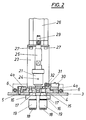
- Each device has two horizontal guide rails 1, 2 arranged transversely to the chain and laterally outside the circulation path of the chain pins, in which a support plate 3 for the device can be displaced to the front and back to a limited extent, springs possibly being provided, which plate 3 approximately in the hold in the position shown in the drawing.
- the plate 3 is supplemented by vertical rails 4 for a guide for a carriage 5.
- tension springs 6 are attached, which are supported with their upper ends by means of cross bolts 7 and hold a crossbeam 8 with their lower ends, which is pulled by the spring preload from below against the stops formed by the ends of the overlapping parts 4a of the rails 4 .
- This bar 8 carries a buffer 9 which engages in a recess in the carriage 5 and which, together with the springs 6, softly abrades the carriage 5 returning to the initial waiting position catches.
- the springs 6 allow the carriage 5 to be adjusted from the stop position down to the end of the rails 4 under the action of force.
- the support plate 3 has an opening 10, the mutually symmetrical flanks of which form a link guide which defines a lubrication path section 11, an upper release section 12 and a lower release section 13, an opening region 14 adjoining the section 13, which enables pivot pins 15 to pass through, with which two opposite arms 16 are mounted on the slide.
- the pivot pins 15 carry guide rollers 17 which are in engagement with the linkages 11 to 14 and are provided at the free end with axes 18 on which two centering rollers 19 are mounted.
- the links 16 enclose with one another an opening for the insertion lug 20 of a lubricating head 21, this insertion lug 20 carrying a front stop part 22 which is intended for engagement in a grease nipple of the chain pin.
- the above-mentioned opening between the centering rollers 19 runs in the case of rollers 17 which are in engagement with the link part 11, concentric to the axis of the lubricating head 21 and is sized in relation to the diameter of the chain pin, so that in the aforementioned position of the rollers 19, one on the rollers of the chain pin at the bottom is centered on the lubricating head axis. If the case mentioned occurs with a rotating chain, then the incoming chain pin takes the carriage 5 along via the rollers 19 and the links 16.
- the lubricating head 21 forms a metering cylinder to which a lubricant line can be connected via a nipple 24.
- the filling quantity of the metering cylinder 21 can be adjusted by turning an actuating piston 25.
- the piston 25 is pneumatic actuatable cylinder piston drive 26 connected to the drive, which is fastened to the frame 23 with retaining screws 27. Via this piston drive, the pneumatic connections of which have been designated 28, 29, the lubricating head 21 can be adjusted forwards and backwards and, in the starting position, delivers the set amount of lubricant to the coupled lubricating nipple of the chain pin.
- a switch 30 with a stop roller 31 sits on the rail 4 (FIG. 2), which responds as soon as the slide 5 has been adjusted a predetermined path along the link part 11. With this response - the line connection between the switch 30 and the piston drive 26 or the connections 28, 29 can be designed electrically or pneumatically - the lubricating head 21 is turned on and reset after a time given by the control link 32 for the roller.
- air is also supplied to a blow-out nozzle 33 in the carrier 1, so that the lubricating nipple of the next chain pin located there is cleaned by blowing off.
Landscapes
- Engineering & Computer Science (AREA)
- General Engineering & Computer Science (AREA)
- Mechanical Engineering (AREA)
- Devices For Conveying Motion By Means Of Endless Flexible Members (AREA)
- General Details Of Gearings (AREA)
Applications Claiming Priority (2)
| Application Number | Priority Date | Filing Date | Title |
|---|---|---|---|
| AT328487A AT391013B (de) | 1987-12-14 | 1987-12-14 | Vorrichtung zum schmieren von laufrollen, kettenbolzen u. dgl. |
| AT3284/87 | 1987-12-14 |
Publications (3)
| Publication Number | Publication Date |
|---|---|
| EP0324332A2 true EP0324332A2 (fr) | 1989-07-19 |
| EP0324332A3 EP0324332A3 (en) | 1989-12-20 |
| EP0324332B1 EP0324332B1 (fr) | 1993-03-24 |
Family
ID=3548191
Family Applications (1)
| Application Number | Title | Priority Date | Filing Date |
|---|---|---|---|
| EP88890319A Expired - Lifetime EP0324332B1 (fr) | 1987-12-14 | 1988-12-14 | Dispositif de graissage de boulons de chaîne |
Country Status (3)
| Country | Link |
|---|---|
| EP (1) | EP0324332B1 (fr) |
| AT (1) | AT391013B (fr) |
| DE (1) | DE3879665D1 (fr) |
Cited By (2)
| Publication number | Priority date | Publication date | Assignee | Title |
|---|---|---|---|---|
| FR2700200A1 (fr) * | 1993-01-06 | 1994-07-08 | Trans Hydro | Procédé de commande d'une installation de lubrification. |
| US6755295B2 (en) * | 1999-05-26 | 2004-06-29 | Wes-Tech, Inc. | Automatic chain track lubricator |
Family Cites Families (9)
| Publication number | Priority date | Publication date | Assignee | Title |
|---|---|---|---|---|
| DE710004C (de) * | 1938-04-20 | 1941-09-01 | Emil Hofmann | Selbsttaetige Schmiervorrichtung fuer auf gerader Strecke vorbeiwandernde gleichartige Schmierstellen |
| US2502659A (en) * | 1947-01-31 | 1950-04-04 | Crouse Hinds Co | Conveyer chain lubrication |
| GB724347A (en) * | 1953-05-09 | 1955-02-16 | W J Jenkins & Company Ltd | Improvements in automatic lubricating mechanism |
| US2905271A (en) * | 1957-09-30 | 1959-09-22 | Alexander H Lippe | Automatic pressure lubricator |
| GB1092602A (en) * | 1964-05-29 | 1967-11-29 | Tecalemit Engineering | Automatic lubricating apparatus for use in lubricating the bearings of rollers or wheels of mobile conveying apparatus |
| GB1272967A (en) * | 1968-07-30 | 1972-05-03 | Tokyo Shibaura Electric Co | Apparatus for supplying lubricant to chain links |
| US4159046A (en) * | 1977-08-29 | 1979-06-26 | C. L. Frost & Son, Inc. | Chain lubrication apparatus and method |
| DE3312589C2 (de) * | 1983-04-08 | 1985-05-15 | Bielomatik Leuze Gmbh + Co, 7442 Neuffen | Vorrichtung zum Schmieren von laufenden Ketten |
| DE3700782A1 (de) * | 1987-01-13 | 1988-07-28 | Limon Fluhme & Co De | Schmierstoff-injektor und vorrichtung zur schmierung von wandernden schmierstellen |
-
1987
- 1987-12-14 AT AT328487A patent/AT391013B/de not_active IP Right Cessation
-
1988
- 1988-12-14 EP EP88890319A patent/EP0324332B1/fr not_active Expired - Lifetime
- 1988-12-14 DE DE8888890319T patent/DE3879665D1/de not_active Expired - Fee Related
Cited By (2)
| Publication number | Priority date | Publication date | Assignee | Title |
|---|---|---|---|---|
| FR2700200A1 (fr) * | 1993-01-06 | 1994-07-08 | Trans Hydro | Procédé de commande d'une installation de lubrification. |
| US6755295B2 (en) * | 1999-05-26 | 2004-06-29 | Wes-Tech, Inc. | Automatic chain track lubricator |
Also Published As
| Publication number | Publication date |
|---|---|
| ATA328487A (de) | 1990-01-15 |
| EP0324332A3 (en) | 1989-12-20 |
| EP0324332B1 (fr) | 1993-03-24 |
| DE3879665D1 (de) | 1993-04-29 |
| AT391013B (de) | 1990-08-10 |
Similar Documents
| Publication | Publication Date | Title |
|---|---|---|
| DE2825213C2 (de) | Vorrichtung zum Überführen von Gegenständen aus einer Förderbahn in eine Arbeitsstation | |
| DE3215744C2 (de) | Verteilförderanlage für Stückgut | |
| AT412397B (de) | Vorrichtung zum ausrichten und/oder sortieren von einzelteilen | |
| DE202007013933U1 (de) | Vorrichtung zum gruppenweisen Verteilen von Behältern | |
| DE3246129A1 (de) | Vorrichtung zum genauen anhalten von fahrzeugen | |
| DE3641326C2 (fr) | ||
| DE202017102428U1 (de) | Umsetzeinrichtung | |
| DE20114728U1 (de) | Schmiereinrichtung | |
| EP0059984A2 (fr) | Dispositif de distribution pour un convoyeur | |
| DE3832865C1 (en) | Assembly station having a duplex conveyor | |
| DE2303425C3 (de) | Hängebahnanlage mit Transporteinheiten | |
| EP0116126A1 (fr) | Rayonnage avec au moins un transtockeur | |
| DE3240962C2 (de) | Palettenwechselvorrichtung | |
| AT391013B (de) | Vorrichtung zum schmieren von laufrollen, kettenbolzen u. dgl. | |
| EP0203949A1 (fr) | Procede et installation pour amarrer a une surface portante fixe un element de support formant surface portante. | |
| DE2108798B2 (de) | Übergabe- und Zentriereinrichtung zu einem Aufzug | |
| DE710004C (de) | Selbsttaetige Schmiervorrichtung fuer auf gerader Strecke vorbeiwandernde gleichartige Schmierstellen | |
| EP0196582B1 (fr) | Dispositif de déplacement pour palettes | |
| DE2100253C3 (de) | Haltestation für eine Schleppkettenkreisförderanlage | |
| DE3930370A1 (de) | Schnelleinzugseinrichtung fuer werkstuecktraeger | |
| DE3129132C2 (de) | Automatische Schmier- und Reinigungsvorrichtung | |
| DE2744793C2 (de) | Einrichtung zum Ordnen von auf einem Rollenförderer stehend nach einer Faßbehandlungsmaschine geförderten, einen zentralen bodenseitigen Anschlußstutzen aufweisenden Fässern | |
| DE1127915B (de) | Bogenstapler | |
| DD277858A1 (de) | Lager- und zufuehrvorrichtung fuer rollenfoermiges stangenmaterial fuer werkzeugmaschinen, insbesondere sickenmaschinen | |
| DE2952258C2 (de) | Sortiervorrichtung zum automatischen Auswählen und Zuführen von ordnungsgemäß aus mechanischen Teilen zusammengefügten Körpern |
Legal Events
| Date | Code | Title | Description |
|---|---|---|---|
| PUAI | Public reference made under article 153(3) epc to a published international application that has entered the european phase |
Free format text: ORIGINAL CODE: 0009012 |
|
| AK | Designated contracting states |
Kind code of ref document: A2 Designated state(s): BE DE FR GB IT NL SE |
|
| PUAL | Search report despatched |
Free format text: ORIGINAL CODE: 0009013 |
|
| AK | Designated contracting states |
Kind code of ref document: A3 Designated state(s): BE DE FR GB IT NL SE |
|
| 17P | Request for examination filed |
Effective date: 19900601 |
|
| 17Q | First examination report despatched |
Effective date: 19910725 |
|
| RTI1 | Title (correction) | ||
| GRAA | (expected) grant |
Free format text: ORIGINAL CODE: 0009210 |
|
| AK | Designated contracting states |
Kind code of ref document: B1 Designated state(s): BE DE FR GB IT NL SE |
|
| REF | Corresponds to: |
Ref document number: 3879665 Country of ref document: DE Date of ref document: 19930429 |
|
| GBT | Gb: translation of ep patent filed (gb section 77(6)(a)/1977) |
Effective date: 19930413 |
|
| ET | Fr: translation filed | ||
| ITF | It: translation for a ep patent filed | ||
| PG25 | Lapsed in a contracting state [announced via postgrant information from national office to epo] |
Ref country code: GB Effective date: 19931214 |
|
| PG25 | Lapsed in a contracting state [announced via postgrant information from national office to epo] |
Ref country code: SE Effective date: 19931215 |
|
| PG25 | Lapsed in a contracting state [announced via postgrant information from national office to epo] |
Ref country code: BE Effective date: 19931231 |
|
| PLBE | No opposition filed within time limit |
Free format text: ORIGINAL CODE: 0009261 |
|
| STAA | Information on the status of an ep patent application or granted ep patent |
Free format text: STATUS: NO OPPOSITION FILED WITHIN TIME LIMIT |
|
| 26N | No opposition filed | ||
| BERE | Be: lapsed |
Owner name: NEUSON HYDRAULIK G.M.B.H. U. CO. K.G. Effective date: 19931231 |
|
| PG25 | Lapsed in a contracting state [announced via postgrant information from national office to epo] |
Ref country code: NL Effective date: 19940701 |
|
| GBPC | Gb: european patent ceased through non-payment of renewal fee |
Effective date: 19931214 |
|
| NLV4 | Nl: lapsed or anulled due to non-payment of the annual fee | ||
| PG25 | Lapsed in a contracting state [announced via postgrant information from national office to epo] |
Ref country code: FR Effective date: 19940831 |
|
| PG25 | Lapsed in a contracting state [announced via postgrant information from national office to epo] |
Ref country code: DE Effective date: 19940901 |
|
| REG | Reference to a national code |
Ref country code: FR Ref legal event code: ST |
|
| EUG | Se: european patent has lapsed |
Ref document number: 88890319.2 Effective date: 19940710 |
|
| PG25 | Lapsed in a contracting state [announced via postgrant information from national office to epo] |
Ref country code: IT Free format text: LAPSE BECAUSE OF NON-PAYMENT OF DUE FEES;WARNING: LAPSES OF ITALIAN PATENTS WITH EFFECTIVE DATE BEFORE 2007 MAY HAVE OCCURRED AT ANY TIME BEFORE 2007. THE CORRECT EFFECTIVE DATE MAY BE DIFFERENT FROM THE ONE RECORDED. Effective date: 20051214 |