EP0324406B2 - Zurüstung in dem Walzensystem eines Kalanders - Google Patents
Zurüstung in dem Walzensystem eines Kalanders Download PDFInfo
- Publication number
- EP0324406B2 EP0324406B2 EP89100263A EP89100263A EP0324406B2 EP 0324406 B2 EP0324406 B2 EP 0324406B2 EP 89100263 A EP89100263 A EP 89100263A EP 89100263 A EP89100263 A EP 89100263A EP 0324406 B2 EP0324406 B2 EP 0324406B2
- Authority
- EP
- European Patent Office
- Prior art keywords
- rolls
- roll
- spindle
- lifting
- lightening
- Prior art date
- Legal status (The legal status is an assumption and is not a legal conclusion. Google has not performed a legal analysis and makes no representation as to the accuracy of the status listed.)
- Expired - Lifetime
Links
- 230000000284 resting effect Effects 0.000 abstract 1
- 238000009826 distribution Methods 0.000 description 3
- 238000003490 calendering Methods 0.000 description 2
- 238000010276 construction Methods 0.000 description 2
- 230000001955 cumulated effect Effects 0.000 description 2
- 230000000694 effects Effects 0.000 description 2
- 230000006835 compression Effects 0.000 description 1
- 238000007906 compression Methods 0.000 description 1
- 230000002950 deficient Effects 0.000 description 1
- 238000007599 discharging Methods 0.000 description 1
- 230000009977 dual effect Effects 0.000 description 1
- 239000000725 suspension Substances 0.000 description 1
Images



Classifications
-
- D—TEXTILES; PAPER
- D21—PAPER-MAKING; PRODUCTION OF CELLULOSE
- D21G—CALENDERS; ACCESSORIES FOR PAPER-MAKING MACHINES
- D21G1/00—Calenders; Smoothing apparatus
- D21G1/002—Opening or closing mechanisms; Regulating the pressure
Definitions
- the invention concerns a supercalender according to the preamble of claim 1 for equalizing the profiles of linear loads between the rolls, said system of rolls comprising an upper roll, a lower roll, several intermediate rolls placed between the upper roll and the lower roll, as well as lifting spindles placed at both sides of the system of rolls.
- the system of rolls in a conventional supercalender comprises a number of rolls, usually 8 to 14 rolls, which are arranged one above the other as a stack of rolls.
- the rolls placed one above the other are in nip contact with each other, and the paper web to be calendered is arranged to run through the nips between the rolls.
- the rolls in the system of rolls are mounted rotably in bearing housings, which are again provided with fastening brackets that are fitted as freely gliding on vertical lifting spindles,
- one of the functions of the lifting spindles is to act as guides so as to keep the rolls in the system of rolls in the correct position
- the bearing housings of the rolls in the system of rolls are not fixed rigidly to the calender frame, but the bearing housings, and consequently also the rolls, can move vertically.
- lightening means have been arranged between said bearing housings or fastening brackets of said rolls and spindle nuts placed underneath said bearing housings or brackets respectively so as to raise the bearing housings while supported on the spindle nuts.
- the lightening means is lowered apart from the bearing housing so as to be axially supported by the spindle nut but freely rotatable when the lifting spindle is desired to be rotated.
- the lightening device according to the invention is thus a unit totally separate from the spindle nuts.
- Fig. 1A is a schematical illustration of a roll 50 provided with bearing housings 51 and lowered on a plane base B.
- Fig. 1B shows the profile of the linear load of a roll 50 as shown in Fig. 1A.
- the linear load produced by the roll 50 is not smooth, but the masses of the bearing housings 51 and of auxiliary devices attached to them, if any, cause that the linear load p is higher in the lateral areas a of the nip than at the middle.
- the linear loads in the nips in the system of rolls are formed exactly in accordance with Fig. 1B.
- Fig. 2 is a schematical side view of the system of rolls 30 of a supercalender as well as of the frame 31 of the calender.
- the figure has been simplified so that, with the exception of the system of rolls 30, the other devices included in the supercalender have been omitted in the illustration.
- the system of rolls 30 of the supercalender comprises an upper roll 32, a lower roll 33, as well as a number of intermediate rolls 36 placed one above the other between the upper roll and the lower roll, said rolls being arranged so that they are in nip contact with each other.
- the upper roll 32 is provided with upper cylinders 34 provided at each end of the roll, by means of which said cylinder the system of rolls can be loaded so as to produce the desired level of linear load.
- the lower roll 33 is also provided with lower cylinders 35 provided at each end of the roll, by means of which said cylinders 35 the system of rolls 30 can be opened.
- the intermediate rolls 36 in the system of rolls, of which only one is provided with reference numerals in Fig. 2 are mounted rotably at both ends in bearing housings 38.
- the system or rolls 30 is provided with lifting spindles 40 placed at each side of the calender frame 31.
- the lifting spindle 40 is suspended on the fastening bracket of the upper cylinder 34 by means of an inwardly threaded stationary nut 41 which is attached non-rotably.
- a drive cogwheel 42 is fixed, which is rotated by means of a switching motor 43.
- the bearing housings 38 of the rolls in the system of rolls 30 are provided with brackets 39, which are fitted on the spindle 40 so as to be displaceable in the longitudinal direction of the spindle.
- each spindle nut 44 is provided on the lifting spindle 40, which said nuts are arranged so as to be placed at a certain distance from the brackets 39 in a normal running situation.
- Each spindle nut 44 is advantageously provided with an adjustable friction member, by means of which a suitable and sufficient friction is produced between the spindle nut 44 and the lifting spindle 40.
- each spindle nut 44 is provided with a locking device 45 suspended on the bracket 39 of the bearing housing of the corresponding roll, by means of which said locking device the spindle nut 44 can be locked in its position if necessary.
- the spindle nut 44 When the spindle nut 44 is not locked by means of the locking device 45, it revolves along with the spindle 40 by the effect of the friction member when the lifting spindle is rotated. On the contrary, when locked, the spindle nut remains stationary while the lifting spindle 40 revolves.
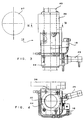
- brackets 39 and the spindle nuts 44 of at least one roll 36, preferably all the rolls, in the system of rolls 30 lightening devices 10 have been installed, which are described in more detail in connection with Figures 3 to 6.
- Figures 3 and 4 show an enlarged and simplified detail at the suspension of one roll in a system of rolls 30 in accordance with Fig. 2.
- the axle journal of the roll is denoted with the reference numeral 37.
- the bearing housing 38 of the roll with its support is provided with a bracket 39, which is fitted slidably on the lifting spindle 40.
- a spindle nut 44 is fitted on the spindle 40, which said nut is provided with a locking device 45, as was already described above.
- the locking device 45 is, e.g., a dual-action pneumatic cylinder, by means of which the spindle nut 44 can be locked unrevolving if needed.
- a lightening device 10 in accordance with the invention is provided, which is operated by means of pressure medium.
- the lightening device 10 is further provided with a device 16 for the distribution of the pressure medium, by means of which said device the pressure medium can be supplied in the desired way to the actuating members of the lightening device 10.
- the construction and operation of the lightening device 10 are described in more detail in connection with Figures 5 and 6.
- the lightening device 10 comprises a frame 11, which is arranged to be mounted on a spindle nut 44. Above the frame 11, a plate 12 is fitted, which reaches contact with the lower face of the bracket 39 of the bearing housing.
- pressure apparatuses are provided, whereat, by supplying pressure medium into said apparatuses, the plate 12 can be raised apart from the frame 11.
- the pressure apparatuses comprise cylinder bores 14 formed into the frame 11 of the lightening device at opposite sides of the lifting spindle 40, said bores 14 being closed at the lower end of the frame 11 and open at the top.
- pistons 15 Into the cylinder bores 14, pistons 15 have been fitted, which rest against the plate 12 provided above the frame 11.
- the top ends of the pistons 15 are appropriately provided with pins 23, which pass into holes 24 formed into the plate 12.
- the pistons 15 can be made to rise upwards in the cylinder bores 14 by supplying pressure medium into the cylinder bores 14 to underneath the pistons 15. Thereby the plate 12 can be made to rise.
- the pressure means 14,15 are advantageously pneumatic or hydraulic, and this is why the lightening device 10 is provided with a pressure-medium distributor device 16, through which the pressure medium is supplied into said pressure means.
- the pressure means When the pressure means are in operation, i.e. when pressure medium is being fed into the cylinder bores 14, the pistons 15 raise the plate 12 upwards, whereby the lightening device 10 raises the bracket 39 and eliminates the distortions of the profile of linear load produced by the masses of the bearing housing 38 of the roll and of any auxiliary devices attached to same.
- the pressure is discharged from the pressure means 14,15. Since the lightening device 10 is appropriately suspended on the bracket 39, discharging of the pressure from the pressure means 14,15 does not necessarily lift the lightening device apart from the spindle nut 44. In order to ensure such detaching, the lightening device 10 is, thus, provided with means that raise the lightening device 10 apart from the spindle nut 44, whereby it is possible to rotate the spindle 40.
- These means comprise bores 25 formed into the frame 11 of the lightening device and arranged crosswise relative the pressure apparatuses at opposite sides of the spindle 40.
- a screw 17 has been fitted, which extends through the frame 11 of the lightening device into the plate 12.
- the end of the screw spindle 20 is provided with an end threading 18, which has been turned into the hole in the plate 12, which is provided with inside threading.
- a lock nut 19 has been additionally turned onto the end threading 18 on the spindle, said nut 19 being tightened against the lower face of the plate 12.
- a bushing 22 has been fitted onto the screw 17, said bushing extending into the bore 25 formed into the frame 11 of the lightening device.
- the bushing 22 is attached to the screw 17 rigidly. At the upper end of the bore 25, there are shoulders 26, and a compression spring 21 is fitted between said shoulders 26 and the bushing 22. Thus, when the pressure is discharged from the pressure means 14,15, the springs 21 push the shoulders 26 and the bushings 22 at each bore 25 apart from each other and, at the same time, lift the frame 11 of the lightening device apart from the spindle nut 44.
- the lightening device 10 is further provided with a protection 13 attached to the plate 12 and partly extending onto the frame 11 of the lightening device and, thus, protecting the pressure apparatuses 14 and 15 of the lightening device.
- the raising force of the lightening device 10 is adjusted so that the masses of the bearing housings 38 and of the auxiliary devices are neutralized.
- the control of the equipment is appropriately arranged as taking place directly from the logic of the calender, whereby the equipment does not require manual or external handling.
Landscapes
- Paper (AREA)
- Diaphragms For Electromechanical Transducers (AREA)
- Input Circuits Of Receivers And Coupling Of Receivers And Audio Equipment (AREA)
- Rolls And Other Rotary Bodies (AREA)
- Treatment Of Fiber Materials (AREA)
- Manufacturing Of Magnetic Record Carriers (AREA)
- Casting Or Compression Moulding Of Plastics Or The Like (AREA)
Claims (1)
- Superkalander mit einer oberen Walze (32), einer unteren Walze (33), mehreren Zwischenwalzen (36), die zwischen der oberen Walze und der unteren Walze plaziert sind, wobei die Lagergehäuse (38) der Zwischenwalzen (36) mit Stützen (39) oder dgl. ausgerüstet sind, die gleitend auf Hubspindeln (40) sitzen, die an beiden Seiten des Walzensystems (30) angeordnet sind, und mit Erleichterungsvorrichtungen (10), die zwischen Stützen (39) oder dgl., befestigt am Lagergehäuse mindestens einer Walze (32, 36), und Spindelmuttern (44) angeordnet sind, welche unterhalb der Stützen auf den Hubspindeln (40) plaziert sind, um die Lagergehäuse (38) anzuheben, während sie auf den Spindelmuttern (44) abgestützt sind,
dadurch gekennzeichnet,
daß jede Erleichterungsvorrichtung (10) am entsprechenden Lagergehäuse (38) oder an der an dem Lagergehäuse befestigten Stütze (39) aufgehängt ist, und daß jede Erleichterungsvorrichtung (10) mit Mitteln (17-22, 25, 26) zum Anheben der Erleichterungsvorrichtung (10) weg von der Spindelmutter (44) versehen ist zwecks Ermöglichung eines Drehens der Hubspindel (40), wobei die Hebemittel (17-22, 25, 26) mechanisch und federbetätigt sind und in der Erleichterungsvorrichtung (10) kreuzweise in bezug auf Druckzylinder (14, 15) an entgegengesetzten Seiten der Spindel (40) angeordnet sind.
Priority Applications (1)
| Application Number | Priority Date | Filing Date | Title |
|---|---|---|---|
| AT89100263T ATE77110T1 (de) | 1988-01-13 | 1989-01-09 | Zuruestung in dem walzensystem eines kalanders. |
Applications Claiming Priority (2)
| Application Number | Priority Date | Filing Date | Title |
|---|---|---|---|
| FI880137A FI81633C (fi) | 1988-01-13 | 1988-01-13 | Anlaeggning i valsverket av en superkalander. |
| FI880137 | 1988-01-13 |
Publications (3)
| Publication Number | Publication Date |
|---|---|
| EP0324406A1 EP0324406A1 (de) | 1989-07-19 |
| EP0324406B1 EP0324406B1 (de) | 1992-06-10 |
| EP0324406B2 true EP0324406B2 (de) | 1995-07-05 |
Family
ID=8525715
Family Applications (1)
| Application Number | Title | Priority Date | Filing Date |
|---|---|---|---|
| EP89100263A Expired - Lifetime EP0324406B2 (de) | 1988-01-13 | 1989-01-09 | Zurüstung in dem Walzensystem eines Kalanders |
Country Status (6)
| Country | Link |
|---|---|
| US (1) | US4901637A (de) |
| EP (1) | EP0324406B2 (de) |
| AT (1) | ATE77110T1 (de) |
| CA (1) | CA1316735C (de) |
| DE (1) | DE68901724T2 (de) |
| FI (1) | FI81633C (de) |
Families Citing this family (8)
| Publication number | Priority date | Publication date | Assignee | Title |
|---|---|---|---|---|
| DE3942689C2 (de) * | 1989-01-27 | 1999-08-26 | Valmet Corp | Kalander, speziell Superkalander |
| DE4103620C1 (de) * | 1991-02-07 | 1992-02-27 | Sulzer-Escher Wyss Gmbh, 7980 Ravensburg, De | |
| FI96334C (fi) * | 1993-11-24 | 1996-06-10 | Valmet Paper Machinery Inc | Menetelmä paperin tai vastaavan rainamateriaalin kalanteroinnissa ja menetelmää soveltava kalanteri |
| FI107626B (fi) * | 1996-05-06 | 2001-09-14 | Metso Paper Inc | Menetelmä kalanterin, etenkin superkalanterin telaston pika-avauksessa ja hydraulijärjestelmä kalanterin, etenkin superkalanterin telastoa varten |
| FI107275B (fi) * | 2000-03-22 | 2001-06-29 | Metso Paper Inc | Moninippikalanteri ja kalanterointisovitelma |
| US6612228B1 (en) | 2000-07-14 | 2003-09-02 | Metso Paper, Inc. | Calender and method for rebuilding a calender |
| FI121082B (fi) | 2006-10-06 | 2010-06-30 | Metso Paper Inc | Menetelmä ja järjestely telaston pika-avaamiseksi monitelakalenterissa |
| DE202012006303U1 (de) | 2012-07-02 | 2012-07-27 | Metso Paper, Inc. | Vorrichtung zur Bearbeitung einer Faserbahn |
Family Cites Families (8)
| Publication number | Priority date | Publication date | Assignee | Title |
|---|---|---|---|---|
| US3060843A (en) * | 1961-11-09 | 1962-10-30 | Beloit Iron Works | Calender stack deflection control |
| DE1461206A1 (de) * | 1964-10-16 | 1969-03-13 | Eck & Soehne | Kalander |
| DE2423504A1 (de) * | 1974-05-15 | 1975-11-27 | Kleinewefers Ind Co Gmbh | Kalander, insbesondere zur bearbeitung von papierbahnen |
| DE2440688C3 (de) * | 1974-08-24 | 1979-11-29 | Bruderhaus Maschinen Gmbh, 7410 Reutlingen | Vorrichtung zur Steuerung der im Spalt zwischen zwei zusammenwirkenden Walzen auf eine durchlaufende Bahn ausgeübten Druckkraft |
| DE3007452C2 (de) * | 1980-02-28 | 1984-09-20 | Kleinewefers Gmbh, 4150 Krefeld | Verfahren zum Regeln des in einem Kalander ausgeübten Druckes sowie Kalander zur Durchführung dieses Verfahrens |
| DE3043901C2 (de) * | 1980-11-21 | 1982-09-16 | Kleinewefers Gmbh, 4150 Krefeld | Kalander |
| US4501197A (en) * | 1983-10-19 | 1985-02-26 | Beloit Corporation | Supercalender edge nip relieving |
| US4510859A (en) * | 1984-01-23 | 1985-04-16 | Beloit Corporation | Supercalender NIP relieving arrangement |
-
1988
- 1988-01-13 FI FI880137A patent/FI81633C/fi not_active IP Right Cessation
- 1988-12-06 CA CA000585121A patent/CA1316735C/en not_active Expired - Fee Related
- 1988-12-13 US US07/283,985 patent/US4901637A/en not_active Expired - Fee Related
-
1989
- 1989-01-09 DE DE68901724T patent/DE68901724T2/de not_active Expired - Fee Related
- 1989-01-09 AT AT89100263T patent/ATE77110T1/de not_active IP Right Cessation
- 1989-01-09 EP EP89100263A patent/EP0324406B2/de not_active Expired - Lifetime
Also Published As
| Publication number | Publication date |
|---|---|
| FI81633C (fi) | 1990-11-12 |
| FI880137A0 (fi) | 1988-01-13 |
| ATE77110T1 (de) | 1992-06-15 |
| DE68901724T2 (de) | 1996-01-18 |
| FI880137A7 (fi) | 1989-07-14 |
| FI81633B (fi) | 1990-07-31 |
| CA1316735C (en) | 1993-04-27 |
| EP0324406B1 (de) | 1992-06-10 |
| DE68901724D1 (de) | 1992-07-16 |
| EP0324406A1 (de) | 1989-07-19 |
| US4901637A (en) | 1990-02-20 |
Similar Documents
| Publication | Publication Date | Title |
|---|---|---|
| EP0848108B1 (de) | Kalander zum Kalandrieren einer Papier- oder ähnlichen Materialbahn | |
| US5038678A (en) | Calender, in particular a supercalender with multiple relief devices | |
| EP0324406B1 (de) | Zurüstung in dem Walzensystem eines Kalanders | |
| CA1231573A (en) | Supercalender nip relieving arrangement | |
| US5590593A (en) | Mounting arrangement for calendar rolls in a calender | |
| EP0886694B1 (de) | Kalander mit hohem spaltdruck | |
| US5144890A (en) | Actuator of modular construction for rolls of a machine calender | |
| FI89949C (fi) | Valspress med en anordning foer avlastning av en belastningsvals | |
| US4721039A (en) | Method and control apparatus for separating the rolls of a calender | |
| US5673617A (en) | Calendar for full and light calendering | |
| US6758134B2 (en) | Method for rebuilding a calender | |
| CA2387114C (en) | Calender and an arrangement for fastening rolls of a calender | |
| FI101635B (fi) | Kalanterin telapinon nosto- ja kuormituslaite | |
| US6848358B1 (en) | Calender | |
| FI114937B (fi) | Menetelmä monitelakalanterin välitelan lukitsemiseksi | |
| FI116302B (fi) | Nipin kuormituksen säätö- ja/tai lukitussovitelma | |
| WO2001021889A1 (en) | Method and arrangement for control of rolls in a calender | |
| WO2003046280A1 (en) | Soft calender |
Legal Events
| Date | Code | Title | Description |
|---|---|---|---|
| PUAI | Public reference made under article 153(3) epc to a published international application that has entered the european phase |
Free format text: ORIGINAL CODE: 0009012 |
|
| AK | Designated contracting states |
Kind code of ref document: A1 Designated state(s): AT DE FR GB IT SE |
|
| 17P | Request for examination filed |
Effective date: 19900115 |
|
| 17Q | First examination report despatched |
Effective date: 19910328 |
|
| GRAA | (expected) grant |
Free format text: ORIGINAL CODE: 0009210 |
|
| AK | Designated contracting states |
Kind code of ref document: B1 Designated state(s): AT DE FR GB IT SE |
|
| REF | Corresponds to: |
Ref document number: 77110 Country of ref document: AT Date of ref document: 19920615 Kind code of ref document: T |
|
| REF | Corresponds to: |
Ref document number: 68901724 Country of ref document: DE Date of ref document: 19920716 |
|
| ITF | It: translation for a ep patent filed | ||
| ET | Fr: translation filed | ||
| PLBI | Opposition filed |
Free format text: ORIGINAL CODE: 0009260 |
|
| PLBI | Opposition filed |
Free format text: ORIGINAL CODE: 0009260 |
|
| 26 | Opposition filed |
Opponent name: SULZER-ESCHER WYSS GMBH Effective date: 19930303 |
|
| PLAB | Opposition data, opponent's data or that of the opponent's representative modified |
Free format text: ORIGINAL CODE: 0009299OPPO |
|
| 26 | Opposition filed |
Opponent name: KLEINEWEFERS GMBH Effective date: 19930306 Opponent name: SULZER-ESCHER WYSS GMBH Effective date: 19930303 |
|
| R26 | Opposition filed (corrected) |
Opponent name: SULZER-ESCHER WYSS GMBH * 930306 KLEINEWEFERS GMBH Effective date: 19930303 |
|
| EAL | Se: european patent in force in sweden |
Ref document number: 89100263.6 |
|
| PUAH | Patent maintained in amended form |
Free format text: ORIGINAL CODE: 0009272 |
|
| STAA | Information on the status of an ep patent application or granted ep patent |
Free format text: STATUS: PATENT MAINTAINED AS AMENDED |
|
| 27A | Patent maintained in amended form |
Effective date: 19950705 |
|
| AK | Designated contracting states |
Kind code of ref document: B2 Designated state(s): AT DE FR GB IT SE |
|
| ITF | It: translation for a ep patent filed | ||
| ET3 | Fr: translation filed ** decision concerning opposition | ||
| PGFP | Annual fee paid to national office [announced via postgrant information from national office to epo] |
Ref country code: FR Payment date: 19981218 Year of fee payment: 11 |
|
| PGFP | Annual fee paid to national office [announced via postgrant information from national office to epo] |
Ref country code: GB Payment date: 19990114 Year of fee payment: 11 |
|
| PGFP | Annual fee paid to national office [announced via postgrant information from national office to epo] |
Ref country code: SE Payment date: 19990118 Year of fee payment: 11 |
|
| PGFP | Annual fee paid to national office [announced via postgrant information from national office to epo] |
Ref country code: AT Payment date: 19990126 Year of fee payment: 11 |
|
| PGFP | Annual fee paid to national office [announced via postgrant information from national office to epo] |
Ref country code: DE Payment date: 19990128 Year of fee payment: 11 |
|
| PG25 | Lapsed in a contracting state [announced via postgrant information from national office to epo] |
Ref country code: GB Free format text: LAPSE BECAUSE OF NON-PAYMENT OF DUE FEES Effective date: 20000109 Ref country code: AT Free format text: LAPSE BECAUSE OF NON-PAYMENT OF DUE FEES Effective date: 20000109 |
|
| PG25 | Lapsed in a contracting state [announced via postgrant information from national office to epo] |
Ref country code: SE Free format text: LAPSE BECAUSE OF NON-PAYMENT OF DUE FEES Effective date: 20000110 |
|
| GBPC | Gb: european patent ceased through non-payment of renewal fee |
Effective date: 20000109 |
|
| EUG | Se: european patent has lapsed |
Ref document number: 89100263.6 |
|
| PG25 | Lapsed in a contracting state [announced via postgrant information from national office to epo] |
Ref country code: FR Free format text: LAPSE BECAUSE OF NON-PAYMENT OF DUE FEES Effective date: 20000929 |
|
| PG25 | Lapsed in a contracting state [announced via postgrant information from national office to epo] |
Ref country code: DE Free format text: LAPSE BECAUSE OF NON-PAYMENT OF DUE FEES Effective date: 20001101 |
|
| REG | Reference to a national code |
Ref country code: FR Ref legal event code: ST |
|
| PG25 | Lapsed in a contracting state [announced via postgrant information from national office to epo] |
Ref country code: IT Free format text: LAPSE BECAUSE OF NON-PAYMENT OF DUE FEES;WARNING: LAPSES OF ITALIAN PATENTS WITH EFFECTIVE DATE BEFORE 2007 MAY HAVE OCCURRED AT ANY TIME BEFORE 2007. THE CORRECT EFFECTIVE DATE MAY BE DIFFERENT FROM THE ONE RECORDED. Effective date: 20050109 |