EP0324452A2 - Brennstoffeinspritzsystem - Google Patents
Brennstoffeinspritzsystem Download PDFInfo
- Publication number
- EP0324452A2 EP0324452A2 EP89100420A EP89100420A EP0324452A2 EP 0324452 A2 EP0324452 A2 EP 0324452A2 EP 89100420 A EP89100420 A EP 89100420A EP 89100420 A EP89100420 A EP 89100420A EP 0324452 A2 EP0324452 A2 EP 0324452A2
- Authority
- EP
- European Patent Office
- Prior art keywords
- fuel
- fuel injection
- actuator
- cylinder
- injection system
- Prior art date
- Legal status (The legal status is an assumption and is not a legal conclusion. Google has not performed a legal analysis and makes no representation as to the accuracy of the status listed.)
- Granted
Links
Images


Classifications
-
- F—MECHANICAL ENGINEERING; LIGHTING; HEATING; WEAPONS; BLASTING
- F02—COMBUSTION ENGINES; HOT-GAS OR COMBUSTION-PRODUCT ENGINE PLANTS
- F02M—SUPPLYING COMBUSTION ENGINES IN GENERAL WITH COMBUSTIBLE MIXTURES OR CONSTITUENTS THEREOF
- F02M51/00—Fuel-injection apparatus characterised by being operated electrically
- F02M51/04—Pumps peculiar thereto
-
- F—MECHANICAL ENGINEERING; LIGHTING; HEATING; WEAPONS; BLASTING
- F02—COMBUSTION ENGINES; HOT-GAS OR COMBUSTION-PRODUCT ENGINE PLANTS
- F02M—SUPPLYING COMBUSTION ENGINES IN GENERAL WITH COMBUSTIBLE MIXTURES OR CONSTITUENTS THEREOF
- F02M41/00—Fuel-injection apparatus with two or more injectors fed from a common pressure-source sequentially by means of a distributor
- F02M41/02—Fuel-injection apparatus with two or more injectors fed from a common pressure-source sequentially by means of a distributor the distributor being spaced from pumping elements
-
- F—MECHANICAL ENGINEERING; LIGHTING; HEATING; WEAPONS; BLASTING
- F02—COMBUSTION ENGINES; HOT-GAS OR COMBUSTION-PRODUCT ENGINE PLANTS
- F02M—SUPPLYING COMBUSTION ENGINES IN GENERAL WITH COMBUSTIBLE MIXTURES OR CONSTITUENTS THEREOF
- F02M59/00—Pumps specially adapted for fuel-injection and not provided for in groups F02M39/00 -F02M57/00, e.g. rotary cylinder-block type of pumps
- F02M59/20—Varying fuel delivery in quantity or timing
- F02M59/36—Varying fuel delivery in quantity or timing by variably-timed valves controlling fuel passages to pumping elements or overflow passages
- F02M59/366—Valves being actuated electrically
-
- F—MECHANICAL ENGINEERING; LIGHTING; HEATING; WEAPONS; BLASTING
- F02—COMBUSTION ENGINES; HOT-GAS OR COMBUSTION-PRODUCT ENGINE PLANTS
- F02M—SUPPLYING COMBUSTION ENGINES IN GENERAL WITH COMBUSTIBLE MIXTURES OR CONSTITUENTS THEREOF
- F02M63/00—Other fuel-injection apparatus having pertinent characteristics not provided for in groups F02M39/00 - F02M57/00 or F02M67/00; Details, component parts, or accessories of fuel-injection apparatus, not provided for in, or of interest apart from, the apparatus of groups F02M39/00 - F02M61/00 or F02M67/00; Combination of fuel pump with other devices, e.g. lubricating oil pump
- F02M63/0003—Fuel-injection apparatus having a cyclically-operated valve for connecting a pressure source, e.g. constant pressure pump or accumulator, to an injection valve held closed mechanically, e.g. by springs, and automatically opened by fuel pressure
- F02M63/0007—Fuel-injection apparatus having a cyclically-operated valve for connecting a pressure source, e.g. constant pressure pump or accumulator, to an injection valve held closed mechanically, e.g. by springs, and automatically opened by fuel pressure using electrically actuated valves
-
- F—MECHANICAL ENGINEERING; LIGHTING; HEATING; WEAPONS; BLASTING
- F02—COMBUSTION ENGINES; HOT-GAS OR COMBUSTION-PRODUCT ENGINE PLANTS
- F02M—SUPPLYING COMBUSTION ENGINES IN GENERAL WITH COMBUSTIBLE MIXTURES OR CONSTITUENTS THEREOF
- F02M2200/00—Details of fuel-injection apparatus, not otherwise provided for
- F02M2200/21—Fuel-injection apparatus with piezoelectric or magnetostrictive elements
Definitions
- the present invention relates to a fuel injection system for an internal combustion engine.
- Supply of fuel is effected via an inlet 1 by a feed pump 3 driven by a drive shaft 2 coupled with an output shaft of an engine.
- Fuel discharged out of the pump 3 with its pressure being regulated by a pressure regulator valve 5 is supplied to a pump chamber 5 of a pump housing 31.
- the fuel within the pump chamber 5 is used on one hand for lubriation of moving portions, and delivered on the other hand to a high pressure plunger pump 6 via an admission port 12.
- This pump has a plunger 7 which is fixedly secured to a cam disc 8 operatively coupled with a drive shaft 2 such that it is driven via a joint 2A by the drive shaft 2 in timed with the engine revolution speed.
- the cam disc 8 has a plurality of face cams, corresponding in number to the number of cylinders of the engine, and it is lifted when one of the face cams 9 rides over a roller 11 rotatable with a roller ring 10. Thus, it reciprocates through a stroke determined by a cam lift.
- the plunger 7 reciprocates while turning about its axis. This reciprocating movement causes fuel coming into via the admission port 12 to be supplied via a distribution port 13 and a delivery valve 14 to a fuel injection nozzle, not shown.
- Fuel injection amount is adjusted by axially displacing a control sleeve 16 covering a cut-off port 15 formed in the plunger 7. For example, when the opening of the cut-off port 15 is uncovered by the control sleeve 16 owing to its rightward axial displacement, as viewed in Fig. 5, of the plunger 7, fuel supplied under pressure from a high pressure chamber 6A to the distribution port 13 is discharged toward the pump chamber 5 where a relatively low pressure builds up via the cut-off port 15, causing termination of supply of fuel to the distribution port 13.
- the control sleeve 16 is mounted on a link lever assembly 19 cooperating with an accelerator pedal such that it is displaced in response to the amount of depression of the accelerator pedal.
- a governor mechanism 18 driven by the drive shaft 2 effects a correction on the link lever assembly 19, adjusting the amount of fuel injection in such a manner as to keep engine revolution speed at a predetermined constant value corresponding to a depression degree of the accelerator pedal.
- This link lever assembly 19 includes a collector lever 21, a tension lever 22, a start lever 23, and a start spring 24.
- the collector lever 21 is mounted on a pump housing 31 about a pivot B, and it is biased by a compression spring 25 into pressing engagement with a full load adjust screw 26.
- the tension lever 22 and start lever 23 are rotatably arranged about a pivot A.
- the tension lever 22 is subject to a bias force of a tension spring 28 which is varied via a control shaft 27 by a control lever 20 as the control lever 22 rotates.
- This bias force is transmitted to the start lever 23 via the start spring 24, urging the start lever 23 into pressing engagement with a governor sleeve 18f of the governor mechanism 18.
- control sleeve 16 is supported by the start lever 23 via a ball joint 18g.
- the governor mechanism 18 is contained within a main body of the fuel pump at its upper portion, and includes a gear 18a integrally connected to a weight holder 18b which weights 18c are connected to for rotation about connection points 18d. If the weight holder 18b rotates about the governor shaft 18e in response to rotation of the drive shaft 2, the weights 18c rotate also and spreads about their connection points 18d due to centrifugal force. For example, if, with the same accelerator depression degree, the engine revolution speed increases, the governor sleeve 18f is pressed to the right and advances toward the start lever 23 since it is coupled with the governor shaft 18e and engaged with the weights 18c.
- the fuel injection timing is controlled by rotating the roller ring 10.
- the roller ring 10 has a timer slide pin 29 engaged in a timer piston 30 so that it is rotated as the timer piston 30 slides.
- the timer piston 30 is slidably disposed in a cylinder 30A to define a high pressure chamber 32 adjacent to one end face thereof, and a low pressure chamber 34 adjacent to the opposite end face thereof. Fuel pressure is admitted to the high pressure chamber 32 via a passage 33 from the pump chamber 5, while the low pressure chamber 34 communicates with the suction side of the feed pump 3, so that the pressure within this chamber is as low as a vacuum pressure. However, the bias force of a spring 35 disposed in the lower chamber 34 pushes the timer piston 30 back toward the high pressure chamber 32. In Fig.
- the timer piston 30 is illustrated in a position where its axis turned through 90 degrees from its original position although the axis of the timer piston 30 extends in a tangential direction to the rotation of the roller ring 10.
- the axis of trhe feed pump 3 illustrated in Fig. 5 has been turned through 90 degrees from its actual position.
- the fuel pressure in the pump chamber 5 increases in proportion to revolution speed of the feed pump 3, so that the timer piston 30 is biased to move to the left, as viewed in Fig. 5, in response to an increase in engine revolution speed.
- This causes the roller ring 10 to rotate in a direction opposite to a direction which the cam disc 8 rotates in, resulting in advancement of the fuel injection timing relative to the engine crank angle.
- the conventional fuel injection system mentioned previously employs a mechanical construction to control a fuel injection amount and an injection timing, so that the mechanical construction inevitably become complicated, making assembly of component parts and subsequent adjustment thereof difficult. Since the precision degree of machning a cam disc or the like has a limit, there occurs variations of fuel injection amount among different cylinders, so that it is difficult to provide stable engine operation at idling.
- the fuel injection amount is determined by its duration. The duration is decreased when it is desired to decrease fuel injection amount. This, however, does not necessarily provide fuel supply characteristic which is fit for running condition. For example, this results in providing a poor exhaust gas composition during operation with low load. Besides, the conventional fuel injection system is heavy, and requires increased cost, thus hampering wide spread of diesel engine mounted passenger cars.
- the present invention aims at providing a superior fuel injection system which has solevd the above mentioned problems.
- a fuel injection system including a plurality of fuel injection valves, the fuel injection system comprising: means defining a cylinder; a plunger disposed in said cylinder; actuator means for reciprocating said plunger in said cylinder; means for defining a fuel supply passage for admitting fuel to said cylinder; means for defining a plurality of fuel delivery passages communicating with said cylinder for distributing fuel among the plurality of injection valves; solenoid valve means for opening or closing said plurality of fuel delivery passages, respectively; and means for controlling said actuator actuator means and said solenoid valve means.
- the actuator means includes a piezoelectric element.
- the controlling means generate a drive signal to the actuator means in the form of the piezoelectric element, causing the actuator to extend or contract, thus reciprocating the plunger in the cylinder.
- This reciprocating movement of the plunger causes induction of fuel into the cylinder via the fuel supply passage, compression thereof to cause discharge under high pressure fuel out of the cylinder.
- the fuel discharged under high pressure is supplied to the corresponding one of the fuel injection valves through the corresponding one of the pressurized fuel delivery passages which is opened by the solenoid valve means, causing fuel injection.
- the fuel injection system uses the actuator means of the quick responsive type and the plurality of solenoid valves, with a simple construction, the fuel injection amount, injection duration and injection timing can be easily and accurately controlled by electrically controlling the actuator means and the solenoid valve means.
- an object of the present invention is to provide a fuel injection system less complicated in construction and increased accuracy in controlling fuel injection amount, injection duration and injection timing.
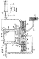
- a pump body 40 is formed with a cylinder 41. Slidably received in the cylinder 41 is a plunger 42 having one end formed with a flange-like base 43 which is coupled with an actuator 44 mounted on the pump body 40.
- the actuator 44 is of the quick response type and is constructed of a piezoelectric element of the laminated type and includes a base end 45 secured to a rear plate 46 of the pump body 40. In response to a drive signal supplied from a control circuit 47 (which will be later described), the actuator 44 extends or contracts in response to the magnitude of electric voltage of the drive signal in accordance with a characteristic as shown in Fig. 2, causing the plunger 42 to reciprocate in the cylinder 41.
- annular passage 48 which is defined between the actuator 44 and the pump body 40.
- the annular passage 48 has a fuel inlet 49 which fuel from a fuel tank, not shown, to be delivered to the annular passage 48 passes through.
- the annular passage 48 is connected to a fuel supply passage 51 and then to the before-mentioned cylinder 41.
- a reverse flow check valve 51 Provided between the fuel supply passage 512 and the cylinder 41 is a reverse flow check valve 51.
- a fuel return passage 53 is connected to the fuel supply passage 51 to return the excessive fuel.
- a plurality of pressurized fuel delivery passages 54 which the valve body 40 is formed with.
- a solenoid valve 55 Provided in each of the pressurized fuel delivery passages 54 is a solenoid valve 55.
- the number of the pressurized fuel delivery passages 54 and solenoid valves 55 correspond to the number of fuel injection valves 56.
- the pressurized fuel delivery passages 54 are connected to the corresponding fuel injection valves 56 at portion downstream of the solenoid valves 55, respectively.
- the reference numeral 47 denotes the control circuit which controls activation of the actuator 44 and the solenoid valves 55. Supplied to this control circuit 47 are a signal from a revolution speed sensor which detects the engine revolution speed, a signal from an accelerator position sensor 58 which detects the position of an accelerator, and a signal from a camshaft angle sensor 59 (which may be replaced with a crank angle sensor). Based on the input signals, the control circuit 47 controls activation of the actuator 44 and the solenoid valves 55.
- the control strategy by the control circuit 47 is such that the corresponding one of the solenoid valves 55 to a cylinder is opened when a piston in the cylinder moves through a period expressed by ⁇ CA° with respect to the compression top dead center (for exmple ⁇ 50° expressed in terms of crank angle).
- the control strategy of the actuator 44 is such that when a piston in one of the cylinders approaches its compression dead center, the actuator 44 begins to be activated at a predetermined angle, and kept activated from a predetermined period of time with a drive signal with a predetermined electric voltage in such a manner as to inject an appropriate amount of fuel at an apprpriate timing which fit the running conditions which the vehicle is involved in.
- Fig. 3 shows a timing chart of the above-mentioned control strategy as being applied to the four cylinder internal combustion engine.
- Activation of the actuator 44 causes the plunger 42 to project deeper into the cylinder 41, pressurizing the fuel within the cylinder 41 and deliver under pressure the fuel out of the cylinder 41 toward the corresponding fuel injection valve 56 via the corresponding solenoid valve 55 which is opened and the corresponding pressurized fuel delivery passage 54, inducting fuel injection.
- the precision degree of the machining process of various component parts is enhanced since the machining process of them becomes easy, and unequal distribution of pressurized fuel is prevented since the fuel distribution is conducted through the fuel delivery passages 54 under the control of solenoid valves 55, so that even distribution of fuel among the engine cylinders is assured.
- the extension movement of the actuator 44 is controlled by the drive signal from the control circuit 47, a good response characteristic is assured.
- the fuel injection timing can be appropriately controlled to the optimum timing by the control circuit 47 in response to various engine operating conditions.
- the actuator 44 extends linearly in accordance with the magnitude of electric voltage of the drive signal and the amount of fuel is injected which is proportional to the amount of stroke of the plunger 42.
- the amount to be injected is easily controlled by adjusting the magnitude of the electric toltage of the drive signal and timing of termination of the drive signal, so that accurate fuel injection control is provided.
- the amount of fuel to be injected and and the timing of fuel injection are controllable by varying the magnitude of electric voltage of the drive signal and the termination timing of the drive signal.
- the solenoid valves 55 provided in the fuel delivery passages 54 may take the form of an ordinary solenoid valve with a relatively slow response characteristic.
- the setting is made such that the cross section of the piezoelectric element is 3000 mm2 and the maximum stroke of the actuator is 100 ⁇ m (micron meter), it is confirmed by experiment that the fuel injection is conducted with a pressure above 200 kg and with the maximum volume of 50 mm3.
- an actuator in the form of a piezoelectric element is used to drive a plunger and a plurality of solenoid valves disposed in pressurized fuel delivery passages, respectively, to open or close them thereby to distribute fuel between fuel injection valves, there is provided a fuel injection system with a simplified construction, with reduced weight, with easy installation and subsequent adjustment, with reduced cost, with little performance distribution among manufactured final products, with superior controllability, with capability to provide appropriate fuel injection amount and timing.
Landscapes
- Engineering & Computer Science (AREA)
- Chemical & Material Sciences (AREA)
- Combustion & Propulsion (AREA)
- Mechanical Engineering (AREA)
- General Engineering & Computer Science (AREA)
- Fuel-Injection Apparatus (AREA)
- Electrical Control Of Air Or Fuel Supplied To Internal-Combustion Engine (AREA)
Applications Claiming Priority (2)
| Application Number | Priority Date | Filing Date | Title |
|---|---|---|---|
| JP3320/88 | 1988-01-11 | ||
| JP63003320A JP2568603B2 (ja) | 1988-01-11 | 1988-01-11 | 燃料噴射装置 |
Publications (3)
| Publication Number | Publication Date |
|---|---|
| EP0324452A2 true EP0324452A2 (de) | 1989-07-19 |
| EP0324452A3 EP0324452A3 (en) | 1989-10-25 |
| EP0324452B1 EP0324452B1 (de) | 1994-03-30 |
Family
ID=11554060
Family Applications (1)
| Application Number | Title | Priority Date | Filing Date |
|---|---|---|---|
| EP89100420A Expired - Lifetime EP0324452B1 (de) | 1988-01-11 | 1989-01-11 | Brennstoffeinspritzsystem |
Country Status (4)
| Country | Link |
|---|---|
| US (1) | US4958610A (de) |
| EP (1) | EP0324452B1 (de) |
| JP (1) | JP2568603B2 (de) |
| DE (1) | DE68914169T2 (de) |
Cited By (4)
| Publication number | Priority date | Publication date | Assignee | Title |
|---|---|---|---|---|
| WO1992014925A3 (de) * | 1991-02-26 | 1993-02-04 | Ficht Gmbh | Kraftstoff-einspritzvorrichtung für brennkraftmaschinen |
| US5836521A (en) * | 1995-03-09 | 1998-11-17 | Dysekompagniet I/S | Valve device with impact member and solenoid for atomizing a liquid |
| EP1167748A3 (de) * | 2000-06-30 | 2004-01-14 | C.R.F. Società Consortile per Azioni | Selbstkompensierender piezoelektrischer Aktuator für ein Steuerventil |
| CN102425516A (zh) * | 2011-11-03 | 2012-04-25 | 北京理工大学 | 多阀喷油系统以及喷油方法 |
Families Citing this family (11)
| Publication number | Priority date | Publication date | Assignee | Title |
|---|---|---|---|---|
| US5176122A (en) * | 1990-11-30 | 1993-01-05 | Toyota Jidosha Kabushiki Kaisha | Fuel injection device for an internal combustion engine |
| JPH07504475A (ja) * | 1992-03-04 | 1995-05-18 | フィヒト ゲゼルシャフト ミット ベシュレンクテル ハフツング | 電磁駆動往復ポンプの励起コイルの駆動用回路 |
| DE4425295A1 (de) * | 1994-07-18 | 1996-01-25 | Bosch Gmbh Robert | Verfahren und Vorrichtung zur Steuerung einer Brennkraftmaschine |
| DE10014451A1 (de) * | 2000-03-23 | 2001-09-27 | Bosch Gmbh Robert | Verfahren und Vorrichtung zur Formung des Einspritzdruckverlaufs an Injektoren |
| EP1138912A1 (de) | 2000-04-01 | 2001-10-04 | Robert Bosch GmbH | Online Optimierung eines Einspritzsystems mit piezolektrischen Elementen |
| DE10146747A1 (de) * | 2001-09-22 | 2003-04-10 | Bosch Gmbh Robert | Kraftstoffeinspritzeinrichtung für eine Brennkraftmaschine |
| JP4377639B2 (ja) * | 2003-09-18 | 2009-12-02 | 株式会社日立ハイテクノロジーズ | ポンプおよびクロマトグラフ用液体ポンプ |
| JP4634085B2 (ja) * | 2004-07-15 | 2011-02-16 | 日本電産サンキョー株式会社 | 多チャンネルポンプ、燃料電池及びそれらの制御方法 |
| EP1657422A1 (de) | 2004-11-12 | 2006-05-17 | C.R.F. Societa' Consortile per Azioni | Verfahren und Vorrichtung zur Steuerung der Kraftstoffeinspritzung einer Brennkraftmaschine |
| US7721716B1 (en) | 2008-07-16 | 2010-05-25 | Harwood Michael R | High pressure piezoelectric fuel injector |
| US9284930B2 (en) | 2011-06-03 | 2016-03-15 | Michael R. Harwood | High pressure piezoelectric fuel injector |
Family Cites Families (16)
| Publication number | Priority date | Publication date | Assignee | Title |
|---|---|---|---|---|
| CH483562A (de) * | 1967-11-10 | 1969-12-31 | Sulzer Ag | Verfahren für die Einführung von Brennstoff in die Arbeitszylinder einer mehrzylindrigen Kolbenbrennkraftmaschine sowie Vorrichtung zur Ausführung des Verfahrens |
| DE1801156A1 (de) * | 1968-10-04 | 1970-04-16 | Teldix Luftfahrt Ausruestung | Kraftstoff-Einspritzvorrichtung mit einer durch eine bewegliche Wand abgeteilten Doppelkammer |
| US3851635A (en) * | 1969-05-14 | 1974-12-03 | F Murtin | Electronically controlled fuel-supply system for compression-ignition engine |
| US3983855A (en) * | 1973-07-12 | 1976-10-05 | C.A.V. Limited | Fuel injection system |
| GB1537669A (en) * | 1975-03-04 | 1979-01-04 | Cav Ltd | Fuel injection pumping apparatus |
| US4374511A (en) * | 1980-12-22 | 1983-02-22 | Ford Motor Company | Fuel injection pump with distributor type fuel control |
| JPS58210357A (ja) * | 1982-06-01 | 1983-12-07 | Nippon Soken Inc | 燃料噴射装置 |
| US4475507A (en) * | 1982-07-21 | 1984-10-09 | Nippondenso Co., Ltd. | Fuel injection amount control |
| JPH0233875B2 (ja) * | 1983-07-15 | 1990-07-31 | Nippon Jidosha Buhin Sogo Kenkyusho Kk | Denwaishikiekiatsuhatsuseisochi |
| JPS60104762A (ja) * | 1983-11-10 | 1985-06-10 | Nippon Soken Inc | 電歪式アクチュエータ及びそれを用いた燃料噴射弁 |
| US4635849A (en) * | 1984-05-03 | 1987-01-13 | Nippon Soken, Inc. | Piezoelectric low-pressure fuel injector |
| US4748954A (en) * | 1984-07-16 | 1988-06-07 | Nippon Soken, Inc. | Electrostrictive actuator device and fuel injection device using same |
| DE3436768A1 (de) * | 1984-10-06 | 1986-04-10 | Robert Bosch Gmbh, 7000 Stuttgart | Verfahren zur steuerung der kraftstoffeinspritzung bei brennkraftmaschinen und kraftstoffeinspritzsystem zur durchfuehrung des verfahrens |
| JPS61157763U (de) * | 1985-03-25 | 1986-09-30 | ||
| JPS61252846A (ja) * | 1985-05-01 | 1986-11-10 | Nippon Soken Inc | 電気的に付勢される駆動要素を有する燃料噴射弁制御装置 |
| JPH07101021B2 (ja) * | 1986-11-07 | 1995-11-01 | 日本電装株式会社 | シングルドライブ・多重ノズル式電子制御式圧電式燃料噴射装置 |
-
1988
- 1988-01-11 JP JP63003320A patent/JP2568603B2/ja not_active Expired - Lifetime
-
1989
- 1989-01-10 US US07/295,620 patent/US4958610A/en not_active Expired - Fee Related
- 1989-01-11 EP EP89100420A patent/EP0324452B1/de not_active Expired - Lifetime
- 1989-01-11 DE DE68914169T patent/DE68914169T2/de not_active Expired - Fee Related
Cited By (7)
| Publication number | Priority date | Publication date | Assignee | Title |
|---|---|---|---|---|
| WO1992014925A3 (de) * | 1991-02-26 | 1993-02-04 | Ficht Gmbh | Kraftstoff-einspritzvorrichtung für brennkraftmaschinen |
| US5540206A (en) * | 1991-02-26 | 1996-07-30 | Ficht Gmbh | Fuel injection device for internal combustion engines |
| US5836521A (en) * | 1995-03-09 | 1998-11-17 | Dysekompagniet I/S | Valve device with impact member and solenoid for atomizing a liquid |
| EP1167748A3 (de) * | 2000-06-30 | 2004-01-14 | C.R.F. Società Consortile per Azioni | Selbstkompensierender piezoelektrischer Aktuator für ein Steuerventil |
| EP1637728A1 (de) * | 2000-06-30 | 2006-03-22 | C.R.F. Società Consortile per Azioni | Selbstkompensierender piezoelektrischer Aktuator für ein Steuerventil |
| CN102425516A (zh) * | 2011-11-03 | 2012-04-25 | 北京理工大学 | 多阀喷油系统以及喷油方法 |
| CN102425516B (zh) * | 2011-11-03 | 2014-04-16 | 北京理工大学 | 多阀喷油系统以及喷油方法 |
Also Published As
| Publication number | Publication date |
|---|---|
| US4958610A (en) | 1990-09-25 |
| JP2568603B2 (ja) | 1997-01-08 |
| JPH01182554A (ja) | 1989-07-20 |
| DE68914169T2 (de) | 1994-07-14 |
| DE68914169D1 (de) | 1994-05-05 |
| EP0324452A3 (en) | 1989-10-25 |
| EP0324452B1 (de) | 1994-03-30 |
Similar Documents
| Publication | Publication Date | Title |
|---|---|---|
| EP0324452B1 (de) | Brennstoffeinspritzsystem | |
| US4541385A (en) | Fuel injection system for self-igniting internal combustion engines | |
| US4224916A (en) | Timing control for fuel injection pump | |
| US5201297A (en) | Method and apparatus for controlling a high-pressure fuel pumping time in a fuel injection pump | |
| GB1580150A (en) | Fuel injection pump for internal combustion engines | |
| US4476835A (en) | Method for delaying axial movement of a pump piston in a fuel _injection pump for combustion engines, and fuel injection pump for _completing the process | |
| EP0471624B1 (de) | Dieselmotor mit Direkteinspritzung | |
| GB2076075A (en) | A fuel injection pump for internal combustion engines | |
| GB2092223A (en) | Fuel Injection System | |
| GB2086080A (en) | Control of fuel supply in i.c. engines | |
| JP2525363B2 (ja) | エンジンのための燃料噴射ポンプ | |
| US4709676A (en) | Fuel supply system for turbocharged internal combustion engine | |
| US4741314A (en) | Fuel injection pump for internal combustion engine | |
| EP0118385B1 (de) | Kraftstoffeinspritzpumpe mit Kolbenhubsteuerung | |
| US4438746A (en) | Rpm governor for a fuel injection pump | |
| GB1564986A (en) | Governors for fuel injection pumps | |
| US4907560A (en) | Exhaust-gas recirculating system for internal-combustion engines | |
| GB2175052A (en) | Fuel injection pump for internal combustion engines | |
| US4387683A (en) | Fuel injection pump for internal combustion engines | |
| EP0743441B1 (de) | Elektronisch gesteuerte Kraftstoffeinspritzanlage für einen Dieselmotor | |
| JPH0441225Y2 (de) | ||
| US5462033A (en) | Fuel pumping apparatus | |
| CA1065214A (en) | Fuel injection pump and timing control therefor | |
| JPS6165029A (ja) | 電子制御燃料噴射ポンプ | |
| GB2285877A (en) | Fuel-injection pump for internal combustion engines |
Legal Events
| Date | Code | Title | Description |
|---|---|---|---|
| PUAI | Public reference made under article 153(3) epc to a published international application that has entered the european phase |
Free format text: ORIGINAL CODE: 0009012 |
|
| 17P | Request for examination filed |
Effective date: 19890111 |
|
| AK | Designated contracting states |
Kind code of ref document: A2 Designated state(s): DE GB |
|
| PUAL | Search report despatched |
Free format text: ORIGINAL CODE: 0009013 |
|
| AK | Designated contracting states |
Kind code of ref document: A3 Designated state(s): DE GB |
|
| 17Q | First examination report despatched |
Effective date: 19910430 |
|
| GRAA | (expected) grant |
Free format text: ORIGINAL CODE: 0009210 |
|
| AK | Designated contracting states |
Kind code of ref document: B1 Designated state(s): DE GB |
|
| REF | Corresponds to: |
Ref document number: 68914169 Country of ref document: DE Date of ref document: 19940505 |
|
| PLBE | No opposition filed within time limit |
Free format text: ORIGINAL CODE: 0009261 |
|
| STAA | Information on the status of an ep patent application or granted ep patent |
Free format text: STATUS: NO OPPOSITION FILED WITHIN TIME LIMIT |
|
| 26N | No opposition filed | ||
| PGFP | Annual fee paid to national office [announced via postgrant information from national office to epo] |
Ref country code: GB Payment date: 19990114 Year of fee payment: 11 |
|
| PGFP | Annual fee paid to national office [announced via postgrant information from national office to epo] |
Ref country code: DE Payment date: 19990115 Year of fee payment: 11 |
|
| PG25 | Lapsed in a contracting state [announced via postgrant information from national office to epo] |
Ref country code: GB Free format text: LAPSE BECAUSE OF NON-PAYMENT OF DUE FEES Effective date: 20000111 |
|
| GBPC | Gb: european patent ceased through non-payment of renewal fee |
Effective date: 20000111 |
|
| PG25 | Lapsed in a contracting state [announced via postgrant information from national office to epo] |
Ref country code: DE Free format text: LAPSE BECAUSE OF NON-PAYMENT OF DUE FEES Effective date: 20001101 |