EP0324530A2 - Procédé pour fabriquer des pavés dans une presse et presse pour fabriquer lesdits pavés - Google Patents
Procédé pour fabriquer des pavés dans une presse et presse pour fabriquer lesdits pavés Download PDFInfo
- Publication number
- EP0324530A2 EP0324530A2 EP89200498A EP89200498A EP0324530A2 EP 0324530 A2 EP0324530 A2 EP 0324530A2 EP 89200498 A EP89200498 A EP 89200498A EP 89200498 A EP89200498 A EP 89200498A EP 0324530 A2 EP0324530 A2 EP 0324530A2
- Authority
- EP
- European Patent Office
- Prior art keywords
- mould
- stones
- stamp
- dividing walls
- filling pieces
- Prior art date
- Legal status (The legal status is an assumption and is not a legal conclusion. Google has not performed a legal analysis and makes no representation as to the accuracy of the status listed.)
- Granted
Links
Images



Classifications
-
- B—PERFORMING OPERATIONS; TRANSPORTING
- B28—WORKING CEMENT, CLAY, OR STONE
- B28B—SHAPING CLAY OR OTHER CERAMIC COMPOSITIONS; SHAPING SLAG; SHAPING MIXTURES CONTAINING CEMENTITIOUS MATERIAL, e.g. PLASTER
- B28B3/00—Producing shaped articles from the material by using presses; Presses specially adapted therefor
- B28B3/02—Producing shaped articles from the material by using presses; Presses specially adapted therefor wherein a ram exerts pressure on the material in a moulding space; Ram heads of special form
- B28B3/021—Ram heads of special form
-
- B—PERFORMING OPERATIONS; TRANSPORTING
- B28—WORKING CEMENT, CLAY, OR STONE
- B28B—SHAPING CLAY OR OTHER CERAMIC COMPOSITIONS; SHAPING SLAG; SHAPING MIXTURES CONTAINING CEMENTITIOUS MATERIAL, e.g. PLASTER
- B28B15/00—General arrangement or layout of plant ; Industrial outlines or plant installations
- B28B15/005—Machines using pallets co-operating with a bottomless mould; Feeding or discharging means for pallets
-
- B—PERFORMING OPERATIONS; TRANSPORTING
- B28—WORKING CEMENT, CLAY, OR STONE
- B28B—SHAPING CLAY OR OTHER CERAMIC COMPOSITIONS; SHAPING SLAG; SHAPING MIXTURES CONTAINING CEMENTITIOUS MATERIAL, e.g. PLASTER
- B28B7/00—Moulds; Cores; Mandrels
- B28B7/0064—Moulds characterised by special surfaces for producing a desired surface of a moulded article, e.g. profiled or polished moulding surfaces
- B28B7/0085—Moulds characterised by special surfaces for producing a desired surface of a moulded article, e.g. profiled or polished moulding surfaces with surfaces for moulding chamfers
Definitions
- the invention relates to a method for manufacturing stones in a press provided with a mould subdivided in several mouding rooms by means of dividing walls,with a stamp arranged above the mould and being movable up-and -down,with a table arranged under the mould and being movable up-and -down,with supply means for supplying empty product plates below the mould and with discharge means for discharging the product plates carrying stones shaped in the mould,as well as to a press and a mould especially for use in such a method.
- Paving stones and the like need to have a constant length and width to make possible the pavement of a road surface or the like in a regular pattern,whilst such paving stones must be provided with bevelled edges or so-called chamfers.For the thickness dimension the requirements are less strict,as differences in the thickness of the paving stones can be absorbed by the sand bed or the like in which the stones are placed. Therefore it has been quite common so far to manufacture such stones lying in a mould,so that the measures of length and width of the stones are determined by the vertical dividing walls bounding the moulding rooms in the mould,so that a constant measure of length and width can be ensured.
- the stones are thereby shaped in the mould in such a manner that the eventual upper surface of a stone is shaped in the bottom of the mould lying on the moulding plate.
- the upper surface of the stones shaped in such a manner appears to be the least wear-resistant surface of the brick,therefore.
- a purpose of the invention now is to obtain a method whereby such stones provided with chamfers can be produced vertically standing,as a greater production capacity can be achieved herewith as well as a better compression of the material of which the stone is made.
- the upper surfaces of the stones, which are shaped in the mould against the upright side walls of the moulding rooms in the mould obtain a dense surface thereby,which is more wear-resistant than the upper surfaces of the stones produced in the usual manner.
- the stones having bevelled edges and produced in the mould either in a vertical position or in a horizontal position can be efficiently used for paving as the pavier has not to pay particular attention to the position of the stone so that the side of the stone having the bevelled edges is on the upper side.
- the purpose of the device and method according to the invention is to produce a stone or clinker of the type such as illustrated in fig.1, i.e. a preferably elongated stone 1,rectangular in cross-section, which at least at one of its bounding planes is provided with bevelled edges 2.
- mould 3 which is subdivided into moulding rooms 4 by means of longitudinal walls 5 and transverse walls 6.
- the moulding rooms are bevelled near the joining points between the longitudinal walls 5 and the transverse walls 6.
- all angles are bevelled so that a stone shaped in such a moulding room 4 will be provided with bevelled edges at two planes lying opposite each other. It will be apparent that it will also be possible,however, to let the walls 5 and 6 join each other rectangularly at one side of the moulding room 4,so that the stone will be provided with bevelled edges at only one side.
- the moulding mass to be provided in the moulding rooms 4 can be compressed by means of a stamp 7 illustrated in fig.5,which stamp is provided with a number of stamp heads 8.
- each stamp head 8 is provided with a pair of protruding noses 9 for forming bevelled edges at two facing sides of the stone to be formed. It will be apparent,however, that if desired also one of the noses can be left out,so that only at one side of the stone a bevelled edge will be formed by means of a nose 9.
- the mould 3 may be closed at the bottom during shaping of the stones by means of a so-called moulding plate 10, which is provided with upright ribs 11,which have been provided in such a manner that said ribs extend at least substantially under the longitudinal walls 5.
- the ribs protruding outside the longitudinal walls 5 are bounded by sloping boundary planes,so that said parts of the ribs 11 protruding outside the longitudinal walls 5 will form bevelled edges in the stones shaped in the moulding rooms 4.
- bevelled edges will be formed at facing sides of a stone shaped in the moulding room by the ribs 11. It will be possible,however, to bound a rib 11 at one side by means of a vertical plane located in the extension of one side of the relevant longitudinal wall 5,so that the stones 1 shaped in the moulding rooms 4 of the mould will each be provided at only one side with a bevelled edge by the ribs 11.
- stones can be shaped which may be provided, either at one side or at two facing sides, with bevelled edges or so-called chamfers.
- the stones can thereby be produced in the mould with their longitudinal axis arranged vertically on the moulding plate 10,so that with a area of the mould remaining equal a considerably larger amount of stones can be produced than in the case when the stones are produced in the mould with their longitudinal axis parallel to the moulding plate 10.
- Said press comprises a frame,not further illustrated,in which the stamp 7 is arranged movable in vertical direction above the mould 3 mounted in the frame. Furthermore the press is provided with a filling wagon 12, being movable to and fro along rails or the like not further illustrated. Under the mould 3 a table 14,movable up and down by means of adjusting cilinders 13,is arranged. When the table 14 takes its lowest position, illustrated in fig.6, the upper surface of the table 14 is located at the same level as the upper surface of a discharge device 15. Arranged at the side of the table 14 turned away from the discharge device is an adjusting cilinder 16 by means of which a pushing means 17 is movable to and fro in horizontal direction across the table 14 when the table takes the lowest position illustrated in fig.6.
- the device is provided with a conveyor 18,diagrammatically illustrated on the right of the mould in fig.6,which conveyor is not illustrated in the other figures 7 - 11.
- a conveyor By means of said conveyor socalled product plates,preferable being entirely flat at least at their upper side,are supplied into the direction according to arrow A.
- both the product plates 19 and the moulding plate 10 lie in one plane thereby,in which they are displaceable just under the bottom of the mould 3.
- the table 14 For filling the moulding rooms 4 of the mould 3 the table 14 is pressed upward from the position illustrated in fig.6 to the position illustrated in fig.7,whilst the moulding plate 10 is moved on the table by the pushing means 20. Simultaneously or afterwards the stamp 7 is moved upward and the filling wagon is brought above the mould 3,so that the moulding mass in the filling wagon can be deposited from the filling wagon into the moulding rooms 4 of the mould 3.
- the filling wagon is moved back and the stamp 7 is moved downward,as illustrated in fig.8.
- the stamp 7 and/or the mould and/or the table 14 can then be set into vibration for compressing the moulding mass in the moulding rooms 4.
- the conveyor 18 is put into operation for displacing the product plate into the direction according the arrow A.
- one of the product plates 19 is moved under mould 3 as a result of that, whilst simultaneously the moulding plate 10 is pushed back to the original retracted position illustrated in fig.6.
- the table 14 with the relevant product plate 19 resting on the table 14 is moved downward,whilst simultaneously the stones shaped in the mould are pressed downward by means of the stamp heads. It is noted that the construction is such that after compression of the moulding mass in the moulding rooms the stamp heads can still be moved downward through the moulding rooms to near the bottom of the mould for effecting an even removal of the shaped stones from the moulding rooms while moving downward the product plate 19 supported by the table 14.
- the stamp 7 is furthermore provided with stops or spacing means (not shown) provided at the sides of the stamp and extending downward,which are intended to cooperate with stops or spacing means (not shown) fixed to the table 14.
- stops or spacing means not shown
- the spacing means on the stamp during the downward movement of the stamp during vibration of the moulding mass, get into touch with the spacing means on the table a signal can be given as a result of which vibrating is stopped.
- the stones shaped in the mould then have exactly the desired height.
- said abutments or spacing means make sure that the distance between the bottoms of the stamp heads of the stamp and the upper surface of the product plate 19 remains constantly equal during said pressing of the stones out of the mould,so that the adjusted length of the stones is maintained and the stones are not deformed in an undesirable manner.
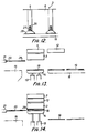
- Fig.12 illustrates a section of a mould 3,whereby the bottom ends of the longitudinal walls 5 are located a little higher than the bottom edges of the transverse walls 6, whilst grooves have been provided in the bottom ends of the longitudinal walls 5. Said grooves serve to accommodate ribs 27,which are fixed to filling pieces 28, which correspond in section with the ribs 11 of a moulding plate 10 described hereinabove. On application of said ribs 28 extending parallel to each other it will not be necessary to use a moulding plate 10 and the stones can be shaped direct on a product plate 19. Using said filling pieces in a press according to the invention will be more fully explained hereinafter with reference to the figs.13-17.
- the conveyor 18,only illustrated in fig.13 again lies on the same level as the discharge means 15. Furthermore the filling pieces 28 extending parallel to each other at the level of the longitudinal walls 5 can here be displaced again by means of the pushing means 20 movable to and fro by means of the adjusting cilinder 21.
- a product plate 19 can be moved on the table by means of the conveyor 18.
- both the table 14 and the stamp 7 can be moved upward to the position illustrated in fig.14 in which then,as indicated in fig.14, the filling pieces can be moved between the product plate 19 and the mould 3 by means of the pushing means 20,whilst the filling wagon 12 can be moved above the mould for filling the mould.
- the protruding ribs provide a good guide for the filling pieces,so that said filling pieces are put in the correct position relative to the mould.
- the ribs also make sure that the filling pieces do not make undesired movements when the filling mass is being compressed in the mould 3.
- the filling wagon After filling the mould 3 the filling wagon can be moved away and the stamp moves downward for compressing the mass put into the mould.
- the stamp and the table may thereby again be provided with the spacing means described hereinabove.
- the filling pieces can be retracted by means of the pushing means 20 again, as illustrated in fig.15 for which purpose the pushing means has been provided with suitable means for taking along the filling pieces.
- the shaped stones can be pressed out of the mould by the simultaneous downward movement of the table 14 and the stamp 7 (fig.16),after which the table can be moved further downward to the level of the conveyor 18 and the discharge means 15 (fig.17).
Landscapes
- Engineering & Computer Science (AREA)
- Chemical & Material Sciences (AREA)
- Ceramic Engineering (AREA)
- Mechanical Engineering (AREA)
- Manufacturing & Machinery (AREA)
- Press-Shaping Or Shaping Using Conveyers (AREA)
Priority Applications (2)
| Application Number | Priority Date | Filing Date | Title |
|---|---|---|---|
| EP89200498A EP0324530B1 (fr) | 1985-08-23 | 1986-08-22 | Procédé pour fabriquer des pavés dans une presse et presse pour fabriquer lesdits pavés |
| AT89200498T ATE98550T1 (de) | 1985-08-23 | 1989-03-01 | Verfahren zum herstellen von steinen in einer presse und presse zum herstellen gennanter steine. |
Applications Claiming Priority (5)
| Application Number | Priority Date | Filing Date | Title |
|---|---|---|---|
| NL8502316 | 1985-08-23 | ||
| NL8502316 | 1985-08-23 | ||
| NL8502484 | 1985-09-11 | ||
| NL8502484A NL8502484A (nl) | 1985-08-23 | 1985-09-11 | Werkwijze en inrichting voor het vervaardigen van stenen in een mal. |
| EP89200498A EP0324530B1 (fr) | 1985-08-23 | 1986-08-22 | Procédé pour fabriquer des pavés dans une presse et presse pour fabriquer lesdits pavés |
Related Parent Applications (2)
| Application Number | Title | Priority Date | Filing Date |
|---|---|---|---|
| EP86201459A Division EP0214684B1 (fr) | 1985-08-23 | 1986-08-22 | Procédé pour fabriquer des pavés dans une presse et presse pour fabriquer lesdits pavés |
| EP86201459.4 Division | 1986-08-22 |
Publications (3)
| Publication Number | Publication Date |
|---|---|
| EP0324530A2 true EP0324530A2 (fr) | 1989-07-19 |
| EP0324530A3 EP0324530A3 (fr) | 1991-05-02 |
| EP0324530B1 EP0324530B1 (fr) | 1993-12-15 |
Family
ID=27232546
Family Applications (1)
| Application Number | Title | Priority Date | Filing Date |
|---|---|---|---|
| EP89200498A Expired - Lifetime EP0324530B1 (fr) | 1985-08-23 | 1986-08-22 | Procédé pour fabriquer des pavés dans une presse et presse pour fabriquer lesdits pavés |
Country Status (2)
| Country | Link |
|---|---|
| EP (1) | EP0324530B1 (fr) |
| AT (1) | ATE98550T1 (fr) |
Cited By (3)
| Publication number | Priority date | Publication date | Assignee | Title |
|---|---|---|---|---|
| WO1993017846A1 (fr) * | 1992-03-04 | 1993-09-16 | Demler S.A. | Procede pour fabriquer des elements en beton moule sous pression, et appareil pour la mise en ×uvre de ce procede |
| ES2138502A1 (es) * | 1996-10-10 | 2000-01-01 | Perez Francisco Fabra | Perfeccionamientos introducidos en las maquinas para la fabricacion de mosaicos. |
| ES2138920A1 (es) * | 1997-12-12 | 2000-01-16 | Frabra Perez Francisco | Equipo de prensas para la fabricacion de mosaicos diversos. |
Family Cites Families (7)
| Publication number | Priority date | Publication date | Assignee | Title |
|---|---|---|---|---|
| US3504408A (en) * | 1965-01-09 | 1970-04-07 | William E Jones | Apparatus for molding interlocking concrete blocks |
| DE1759153A1 (de) * | 1968-04-05 | 1972-02-17 | Josef Hehn | Vorrichtung zum Herstellen von Hohlblocksteinen |
| US4128357A (en) * | 1975-04-08 | 1978-12-05 | Barth Guenter | Slab-elements for covering the ground |
| GB1571461A (en) * | 1977-03-19 | 1980-07-16 | Tiger Machine Seisakusho Kk | Apparatus for moulding concrete blocks by vibration and pressure |
| BE858167A (nl) * | 1977-08-26 | 1977-12-16 | Cuyvers Edward G | Welfselelement en inrichting ter vervaardiging van dergelijke welfselelementen |
| NL8602836A (nl) * | 1986-11-10 | 1988-06-01 | Rook Beheer Bv | Werkwijze voor het vervaardigen van betonblokken. |
| NL8701096A (nl) * | 1987-05-08 | 1988-12-01 | Rook Beheer Bv | Inrichting voor het vervaardigen van stenen. |
-
1986
- 1986-08-22 EP EP89200498A patent/EP0324530B1/fr not_active Expired - Lifetime
-
1989
- 1989-03-01 AT AT89200498T patent/ATE98550T1/de not_active IP Right Cessation
Cited By (3)
| Publication number | Priority date | Publication date | Assignee | Title |
|---|---|---|---|---|
| WO1993017846A1 (fr) * | 1992-03-04 | 1993-09-16 | Demler S.A. | Procede pour fabriquer des elements en beton moule sous pression, et appareil pour la mise en ×uvre de ce procede |
| ES2138502A1 (es) * | 1996-10-10 | 2000-01-01 | Perez Francisco Fabra | Perfeccionamientos introducidos en las maquinas para la fabricacion de mosaicos. |
| ES2138920A1 (es) * | 1997-12-12 | 2000-01-16 | Frabra Perez Francisco | Equipo de prensas para la fabricacion de mosaicos diversos. |
Also Published As
| Publication number | Publication date |
|---|---|
| EP0324530A3 (fr) | 1991-05-02 |
| ATE98550T1 (de) | 1994-01-15 |
| EP0324530B1 (fr) | 1993-12-15 |
Similar Documents
| Publication | Publication Date | Title |
|---|---|---|
| US5082438A (en) | Press for manufacturing stones | |
| US3940229A (en) | Apparatus for manufacturing rough faced bricks | |
| US5846576A (en) | Apparatus for the production of shaped bricks | |
| US5597591A (en) | Apparatus for the production of concrete paving stones | |
| US20110316194A1 (en) | Method And Apparatus For Dry Casting Concrete Blocks Having A Decorative Face | |
| EP0324530B1 (fr) | Procédé pour fabriquer des pavés dans une presse et presse pour fabriquer lesdits pavés | |
| US3504408A (en) | Apparatus for molding interlocking concrete blocks | |
| CN107263674B (zh) | 一种乐高砖成型机 | |
| US2934807A (en) | Removable mold for making batter blocks | |
| EP2528717B1 (fr) | Procédé et appareil de remplissage de moule | |
| US4856976A (en) | Device for manufacturing stones | |
| GB2050917A (en) | Patterning pressed concrete blocks | |
| EP1136211B1 (fr) | Dispositif pour la fabrication d'articles en céramique comme par exemple des dalles, des carreaux et des articles similaires par pressage de poudre | |
| NL194117C (nl) | Inrichting voor het vervaardigen van muurelementen. | |
| US20030082258A1 (en) | Apparatus for molding brick and brick paver | |
| US2987795A (en) | Machine for manufacturing building blocks | |
| CN223369629U (zh) | 一种砖坯压制成型装置 | |
| KR100278088B1 (ko) | 조립식 타일블럭의 제조방법 및 장치 | |
| US2911701A (en) | Block molding means | |
| SU992198A1 (ru) | Форма дл изготовлени железобетонных изделий | |
| US3824059A (en) | Molding machine for producing concrete products | |
| CN120862839B (zh) | 一种适用于焦炉涂釉砖的挤压成型装置 | |
| US4150933A (en) | Apparatus for molding roofing panels having a stepped portion | |
| CN223617921U (zh) | 一种压砖装置 | |
| JP2521465B2 (ja) | コンクリ−ト製品成形装置 |
Legal Events
| Date | Code | Title | Description |
|---|---|---|---|
| PUAI | Public reference made under article 153(3) epc to a published international application that has entered the european phase |
Free format text: ORIGINAL CODE: 0009012 |
|
| AC | Divisional application: reference to earlier application |
Ref document number: 214684 Country of ref document: EP |
|
| AK | Designated contracting states |
Kind code of ref document: A2 Designated state(s): AT BE CH DE FR GB IT LI LU NL SE |
|
| PUAL | Search report despatched |
Free format text: ORIGINAL CODE: 0009013 |
|
| AK | Designated contracting states |
Kind code of ref document: A3 Designated state(s): AT BE CH DE FR GB IT LI LU NL SE |
|
| 17P | Request for examination filed |
Effective date: 19911024 |
|
| 17Q | First examination report despatched |
Effective date: 19920625 |
|
| GRAA | (expected) grant |
Free format text: ORIGINAL CODE: 0009210 |
|
| AC | Divisional application: reference to earlier application |
Ref document number: 214684 Country of ref document: EP |
|
| AK | Designated contracting states |
Kind code of ref document: B1 Designated state(s): AT BE CH DE FR GB IT LI LU NL SE |
|
| PG25 | Lapsed in a contracting state [announced via postgrant information from national office to epo] |
Ref country code: IT Free format text: LAPSE BECAUSE OF FAILURE TO SUBMIT A TRANSLATION OF THE DESCRIPTION OR TO PAY THE FEE WITHIN THE PRE;WARNING: LAPSES OF ITALIAN PATENTS WITH EFFECTIVE DATE BEFORE 2007 MAY HAVE OCCURRED AT ANY TIME BEFORE 2007. THE CORRECT EFFECTIVE DATE MAY BE DIFFERENT FROM THE ONE RECORDED.SCRIBED TIME-LIMIT Effective date: 19931215 Ref country code: AT Effective date: 19931215 Ref country code: FR Effective date: 19931215 Ref country code: SE Effective date: 19931215 |
|
| REF | Corresponds to: |
Ref document number: 98550 Country of ref document: AT Date of ref document: 19940115 Kind code of ref document: T |
|
| REF | Corresponds to: |
Ref document number: 3689422 Country of ref document: DE Date of ref document: 19940127 |
|
| EN | Fr: translation not filed | ||
| PGFP | Annual fee paid to national office [announced via postgrant information from national office to epo] |
Ref country code: CH Payment date: 19940629 Year of fee payment: 9 |
|
| PG25 | Lapsed in a contracting state [announced via postgrant information from national office to epo] |
Ref country code: LU Free format text: LAPSE BECAUSE OF NON-PAYMENT OF DUE FEES Effective date: 19940831 |
|
| PLBE | No opposition filed within time limit |
Free format text: ORIGINAL CODE: 0009261 |
|
| STAA | Information on the status of an ep patent application or granted ep patent |
Free format text: STATUS: NO OPPOSITION FILED WITHIN TIME LIMIT |
|
| 26N | No opposition filed | ||
| PG25 | Lapsed in a contracting state [announced via postgrant information from national office to epo] |
Ref country code: LI Effective date: 19950831 Ref country code: CH Effective date: 19950831 |
|
| REG | Reference to a national code |
Ref country code: CH Ref legal event code: PL |
|
| PGFP | Annual fee paid to national office [announced via postgrant information from national office to epo] |
Ref country code: BE Payment date: 19960711 Year of fee payment: 11 |
|
| PGFP | Annual fee paid to national office [announced via postgrant information from national office to epo] |
Ref country code: GB Payment date: 19960812 Year of fee payment: 11 |
|
| PGFP | Annual fee paid to national office [announced via postgrant information from national office to epo] |
Ref country code: NL Payment date: 19960830 Year of fee payment: 11 |
|
| PGFP | Annual fee paid to national office [announced via postgrant information from national office to epo] |
Ref country code: DE Payment date: 19961030 Year of fee payment: 11 |
|
| PG25 | Lapsed in a contracting state [announced via postgrant information from national office to epo] |
Ref country code: GB Free format text: LAPSE BECAUSE OF NON-PAYMENT OF DUE FEES Effective date: 19970822 |
|
| PG25 | Lapsed in a contracting state [announced via postgrant information from national office to epo] |
Ref country code: BE Free format text: LAPSE BECAUSE OF NON-PAYMENT OF DUE FEES Effective date: 19970831 |
|
| BERE | Be: lapsed |
Owner name: GEBROEDERS ROOK BEHEER B.V. Effective date: 19970831 |
|
| PG25 | Lapsed in a contracting state [announced via postgrant information from national office to epo] |
Ref country code: NL Free format text: LAPSE BECAUSE OF NON-PAYMENT OF DUE FEES Effective date: 19980301 |
|
| GBPC | Gb: european patent ceased through non-payment of renewal fee |
Effective date: 19970822 |
|
| PG25 | Lapsed in a contracting state [announced via postgrant information from national office to epo] |
Ref country code: DE Free format text: LAPSE BECAUSE OF NON-PAYMENT OF DUE FEES Effective date: 19980501 |
|
| NLV4 | Nl: lapsed or anulled due to non-payment of the annual fee |
Effective date: 19980301 |