EP0324559A2 - Closure arrangement including a radio frequency seal - Google Patents
Closure arrangement including a radio frequency seal Download PDFInfo
- Publication number
- EP0324559A2 EP0324559A2 EP89300142A EP89300142A EP0324559A2 EP 0324559 A2 EP0324559 A2 EP 0324559A2 EP 89300142 A EP89300142 A EP 89300142A EP 89300142 A EP89300142 A EP 89300142A EP 0324559 A2 EP0324559 A2 EP 0324559A2
- Authority
- EP
- European Patent Office
- Prior art keywords
- seal
- panel member
- frame
- closure
- aperture
- Prior art date
- Legal status (The legal status is an assumption and is not a legal conclusion. Google has not performed a legal analysis and makes no representation as to the accuracy of the status listed.)
- Withdrawn
Links
Images
Classifications
-
- H—ELECTRICITY
- H05—ELECTRIC TECHNIQUES NOT OTHERWISE PROVIDED FOR
- H05K—PRINTED CIRCUITS; CASINGS OR CONSTRUCTIONAL DETAILS OF ELECTRIC APPARATUS; MANUFACTURE OF ASSEMBLAGES OF ELECTRICAL COMPONENTS
- H05K9/00—Screening of apparatus or components against electric or magnetic fields
- H05K9/0007—Casings
- H05K9/0015—Gaskets or seals
Definitions
- This invention relates to a closure arrangement incorporating an RF seal, i.e. a seal which prevents the transmission of radio-frequency radiation.
- a closure arrangement is particularly useful in a transportable shelter for electrical equipment which is vulnerable to RF radiation.
- a closure arrangement comprising a hinged door in a frame in whose rebate is fixed an RF seal.
- the door, the frame and the rest of the shelter are electrically conductive at least on the outer surface, and the purpose of the seal is to ensure electrical conductivity where the door meets the frame, so that all the incident RF radiation is absorbed.
- the RF seal may be broken or deformed, and may be contaminated with soil or grease or ice, for example. This may significantly impair the RF seal.
- the invention in its first aspect, provides a closure arrangement comprising an aperture-defining frame, a closure panel member which fits removably into the frame to close the aperture, and an RF seal, between the frame and an edge of the panel member, divided into two complementary parts attached respectively to the panel member and to the frame, in parallel planes, the parts extending over different sections of the periphery of the aperture and co-operating to cover the entire periphery only when the panel member is closed.
- the part of the RF seal which extends along the lower horizontal edge of the frame is carried by the panel member (in that case a door), the remainder of the RF seal being attached to the side edges and upper edge of the frame, so that the RF seal is less likely to be damaged.
- a further problem of the transportable shelters described above is the general deterioration of efficiency of the RF seal with use, due to contamination. Moreover, even before the RF seal becomes contaminated, the efficiency of the seal is affected by any irregularity in the surface of the seal or of the edge of the panel member which faces the seal, arising from manufacturing defects or accidental damage.
- the second aspect of the invention provides a closure arrangement comprising an aperture-defining frame with an attached, resiliently deformable, elongate, peripheral RF seal; and a closure panel member with a generally flat edge for engaging and compressing an outer face of the seal; the edge having a continuous land to enhance the contact pressure exerted on the seal locally on a line extending along the seal, upon closure of the aperture by the said closure panel member.
- the enhanced contact pressure improves the electrical contact and is more likely to overcome the effect of any irregularity in the surface of the seal or of the edge of the closure panel.
- the land has the effect of eroding the surface of the seal to remove contaminants, in use.
- the land is preferably a sharp ridge.
- a transportable shelter for electronic equipment comprises an approximately parallelepiped enclosure (not shown) capable of being mounted on a vehicle, and having an outer surface which is electrically conductive.
- One face of the enclosure includes an aperture-defining frame 3 which defines a rebate for a door 1 to which it is connected by a hinge 4 along one vertical side edge.
- the door 1 and panels forming the enclosure are each made from two sheets of aluminium bonded to an extruded foam core. Extruded aluminium channels 1a are fitted over the edges of the door to improve its durability.
- a peripheral RF seal 2 is provided between the frame rebate and the inner face of the edge 1a of the door 1.
- This seal 2 is attached to the two vertical side edges of the frame 3, as shown in Figure 1, and also, in a similar manner, to the upper horizontal edge of the frame 3 (not shown).
- the lower horizontal portion 2a of the RF seal is carried instead by the door 1 on a corresponding edge 1a.
- the seal 2 in its relaxed condition with the door open, has a circular cross-section.
- the seal 2 When the door is closed, in use, the seal 2 is compressed to an oval shape in cross-section, as shown in Figure 1, due to pressure from strips of the opposed flat inner faces of the door edge 1a and the frame 3. This elongation of the cross-sectional shape of the seal 2 causes it to exert a strong pressure against a sharp corner of a ridge 5 projecting from the frame rebate (or from the door edge 1a, as the case may be), to enhance the RF seal. In the relaxed condition, the seal 2 just contacts that sharp corner.
- the edges 1a of the door 1 which engage the RF seal 2 on the frame 3, and the edge of the frame 3 which engages the RF seal 2a on the door 1, are provided with a pair of sharp, parallel ridges 1c extending along the edge.
- each ridge 1c enhances the contact pressure exerted on the seal 2 (or 2a) locally on a line extending along the seal at its centre.
- the regions of the edge 1a immediately adjacent the ridge 1c are flat and compress the whole of the outer face of the corresponding seal 2, but with less pressure.
- the RF seal 2 or 2a comprises a pair of parallel, oval-section, resiliently deformable, silicon compound tubes 21 covered by a metal braid 22.
- a web of the metal braid 22 extends from one tube 21 to the other and is affixed by bolts 23 to the ridge 5 projecting from the frame rebate, or from the door edge 1a, as the case may be.
- the peripheral RF seal is divided into two complementary parts 2, 2a which co-operate to cover the entire periphery only when the door 1 is closed. It will be appreciated that there is an overlap of the different sections of the RF seal at the corners, of which one corner is shown in Figure 2. To prevent any loss of seal due to deformation adjacent the region of overlap, the end of the tube 21 of one only of the sections may be cut back so that, although the braids 22 still overlap to provide the seal, the tubes 21 do not overlap, thus avoiding any significant increase in seal thickness.
- the portion of the RF seal carried by the door is the lower horizontal portion
- the peripheral extent of the two parts of the RF seal may be divided in any desired manner between the door and its frame; indeed, the invention is applicable to any closure arrangement including those in which the closure panel member is positioned above floor level, for example.
Landscapes
- Engineering & Computer Science (AREA)
- Microelectronics & Electronic Packaging (AREA)
- Specific Sealing Or Ventilating Devices For Doors And Windows (AREA)
- Shielding Devices Or Components To Electric Or Magnetic Fields (AREA)
Abstract
A closure arrangement comprises an aperture-defining frame (3), a closure panel member (door 1) which fits removeably into the frame (3), and a radio-frequency (RF) seal (2) between the frame (3) and an edge (1a) of the panel member (1). The seal is divided into two complementary parts attached respectively to the panel member (1) and to the frame (3), the parts extending over different sections of the periphery of the aperture and cooperating to cover the entire periphery only when the panel member is closed. To improve the seal, a sharp ridge (1c) is formed in the edge (1a) of the panel member to enhance the contact pressure exerted on the seal locally on a line extending along the seal.
Description
- This invention relates to a closure arrangement incorporating an RF seal, i.e. a seal which prevents the transmission of radio-frequency radiation. Such a closure arrangement is particularly useful in a transportable shelter for electrical equipment which is vulnerable to RF radiation.
- It has been proposed to provide for such a transportable shelter a closure arrangement comprising a hinged door in a frame in whose rebate is fixed an RF seal. The door, the frame and the rest of the shelter are electrically conductive at least on the outer surface, and the purpose of the seal is to ensure electrical conductivity where the door meets the frame, so that all the incident RF radiation is absorbed.
- One problem with such shelters is that the lower, horizontal edge of the door frame is particularly susceptible to contamination and damage in service when operators move in and out of the shelter: the RF seal may be broken or deformed, and may be contaminated with soil or grease or ice, for example. This may significantly impair the RF seal.
- The invention, in its first aspect, provides a closure arrangement comprising an aperture-defining frame, a closure panel member which fits removably into the frame to close the aperture, and an RF seal, between the frame and an edge of the panel member, divided into two complementary parts attached respectively to the panel member and to the frame, in parallel planes, the parts extending over different sections of the periphery of the aperture and co-operating to cover the entire periphery only when the panel member is closed. In the preferred embodiment, for example, the part of the RF seal which extends along the lower horizontal edge of the frame is carried by the panel member (in that case a door), the remainder of the RF seal being attached to the side edges and upper edge of the frame, so that the RF seal is less likely to be damaged.
- A further problem of the transportable shelters described above is the general deterioration of efficiency of the RF seal with use, due to contamination. Moreover, even before the RF seal becomes contaminated, the efficiency of the seal is affected by any irregularity in the surface of the seal or of the edge of the panel member which faces the seal, arising from manufacturing defects or accidental damage.
- Accordingly, the second aspect of the invention provides a closure arrangement comprising an aperture-defining frame with an attached, resiliently deformable, elongate, peripheral RF seal; and a closure panel member with a generally flat edge for engaging and compressing an outer face of the seal; the edge having a continuous land to enhance the contact pressure exerted on the seal locally on a line extending along the seal, upon closure of the aperture by the said closure panel member. The enhanced contact pressure improves the electrical contact and is more likely to overcome the effect of any irregularity in the surface of the seal or of the edge of the closure panel. Further, it is found that the land has the effect of eroding the surface of the seal to remove contaminants, in use. The land is preferably a sharp ridge.
- In order that the invention may be understood, a preferred embodiment will now be described, by way of example only, with reference to the accompanying drawings, in which:
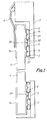
- Figure 1 is a horizontal section through a closure arrangement forming part of a transportable shelter for electronic equipment and constructed in accordance with the first aspect of the invention; and
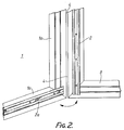
- Figure 2 is a perspective view, from the outside, of one corner of a closure arrangement of a transportable shelter of which the door is open, in accordance with the second aspect of the invention.
- With reference first to Figure 1, a transportable shelter for electronic equipment comprises an approximately parallelepiped enclosure (not shown) capable of being mounted on a vehicle, and having an outer surface which is electrically conductive. One face of the enclosure includes an aperture-defining
frame 3 which defines a rebate for adoor 1 to which it is connected by ahinge 4 along one vertical side edge. Thedoor 1 and panels forming the enclosure, are each made from two sheets of aluminium bonded to an extruded foam core.Extruded aluminium channels 1a are fitted over the edges of the door to improve its durability. - A
peripheral RF seal 2 is provided between the frame rebate and the inner face of theedge 1a of thedoor 1. Thisseal 2 is attached to the two vertical side edges of theframe 3, as shown in Figure 1, and also, in a similar manner, to the upper horizontal edge of the frame 3 (not shown). However, as shown in Figure 2, the lowerhorizontal portion 2a of the RF seal is carried instead by thedoor 1 on acorresponding edge 1a. Theseal 2, in its relaxed condition with the door open, has a circular cross-section. - When the door is closed, in use, the
seal 2 is compressed to an oval shape in cross-section, as shown in Figure 1, due to pressure from strips of the opposed flat inner faces of thedoor edge 1a and theframe 3. This elongation of the cross-sectional shape of theseal 2 causes it to exert a strong pressure against a sharp corner of aridge 5 projecting from the frame rebate (or from thedoor edge 1a, as the case may be), to enhance the RF seal. In the relaxed condition, theseal 2 just contacts that sharp corner. - In accordance with the second aspect of the invention, the
edges 1a of thedoor 1 which engage theRF seal 2 on theframe 3, and the edge of theframe 3 which engages theRF seal 2a on thedoor 1, are provided with a pair of sharp,parallel ridges 1c extending along the edge. In use, upon closure of the aperture by thedoor 1, as shown in Figure 1, eachridge 1c enhances the contact pressure exerted on the seal 2 (or 2a) locally on a line extending along the seal at its centre. The regions of theedge 1a immediately adjacent theridge 1c are flat and compress the whole of the outer face of thecorresponding seal 2, but with less pressure. The result of this is that the electrical contact between theedge 1a and theRF seal ridges 1c, partly because of the enhanced local pressure, and partly because theridges 1c remove contaminants from the surface of the RF seal, upon closure of the door, by abrasion and erosion. - The
RF seal silicon compound tubes 21 covered by ametal braid 22. A web of themetal braid 22 extends from onetube 21 to the other and is affixed bybolts 23 to theridge 5 projecting from the frame rebate, or from thedoor edge 1a, as the case may be. - As stated above, in accordance with the first aspect of the invention, the peripheral RF seal is divided into two
complementary parts door 1 is closed. It will be appreciated that there is an overlap of the different sections of the RF seal at the corners, of which one corner is shown in Figure 2. To prevent any loss of seal due to deformation adjacent the region of overlap, the end of thetube 21 of one only of the sections may be cut back so that, although thebraids 22 still overlap to provide the seal, thetubes 21 do not overlap, thus avoiding any significant increase in seal thickness. - Although in the example described the portion of the RF seal carried by the door is the lower horizontal portion, the peripheral extent of the two parts of the RF seal may be divided in any desired manner between the door and its frame; indeed, the invention is applicable to any closure arrangement including those in which the closure panel member is positioned above floor level, for example.
Claims (7)
1. A closure arrangement characterised by an aperture-defining frame (3), a closure panel member (1) which fits removeably into the frame (3) to close the aperture, and an RF seal (2, 2a), between the frame (3) and an edge (1a) of the panel member (1), divided into two complementary parts (2a, 2) attached respectively to the panel member (1) and to the frame (3), in parallel planes, the parts (2a, 2) extending over different sections of the periphery of the aperture and cooperating to cover the entire periphery only when the panel member (1) is closed.
2. A closure arrangement comprising an aperture-defining frame (3) with an attached, resiliently deformable, elongate, peripheral RF seal (2); and a closure panel member (1) with a generally flat edge for engaging and compressing an outer face of the seal (2); the edge having a continuous land (1c) to enhance the contact pressure exerted on the seal (2) locally on a line extending along the seal (2), upon closure of the aperture by said closure panel member (1).
3. A closure arrangement as claimed in claim 2, in which the land is a sharp ridge (1c).
4. A closure arrangement as claimed in any preceding claim, in which the RF seal (2) comprises a resiliently deformable inner member (21) covered with a flexible, electrically conductive material (22).
5. A closure arrangement as claimed in claim 4, in which the electrically conductive material (22) is a metal mesh.
6. A closure arrangement as claimed in any preceding claim, in which the RF seal comprises resiliently deformable tubing (2).
7. A closure arrangement as claimed in claim 6, in which the tubing (2) is of a silicon compound.
Applications Claiming Priority (2)
| Application Number | Priority Date | Filing Date | Title |
|---|---|---|---|
| GB8800724A GB2214718A (en) | 1988-01-13 | 1988-01-13 | Closure arrangement comprising an rf seal |
| GB8800724 | 1988-01-13 |
Publications (2)
| Publication Number | Publication Date |
|---|---|
| EP0324559A2 true EP0324559A2 (en) | 1989-07-19 |
| EP0324559A3 EP0324559A3 (en) | 1990-01-24 |
Family
ID=10629895
Family Applications (1)
| Application Number | Title | Priority Date | Filing Date |
|---|---|---|---|
| EP89300142A Withdrawn EP0324559A3 (en) | 1988-01-13 | 1989-01-09 | Closure arrangement including a radio frequency seal |
Country Status (4)
| Country | Link |
|---|---|
| US (1) | US4982053A (en) |
| EP (1) | EP0324559A3 (en) |
| JP (1) | JPH01287389A (en) |
| GB (1) | GB2214718A (en) |
Cited By (3)
| Publication number | Priority date | Publication date | Assignee | Title |
|---|---|---|---|---|
| FR2833453A1 (en) * | 2001-12-11 | 2003-06-13 | Getelec | SHIELDING SHAPE IN THE FORM OF A TUBULAR PROFILE ELEMENT OF ELECTROCONDUCTIVE POLYMER MATERIAL |
| WO2005004573A1 (en) * | 2003-06-06 | 2005-01-13 | Getelec | Shield gasket in the form of a tubular extruded element which is made from an electroconductive polymer material |
| DE102010064091A1 (en) | 2010-12-23 | 2012-06-28 | BSH Bosch und Siemens Hausgeräte GmbH | Hochfrequenzgargerät |
Families Citing this family (10)
| Publication number | Priority date | Publication date | Assignee | Title |
|---|---|---|---|---|
| JPH0280781A (en) * | 1988-09-17 | 1990-03-20 | Kitagawa Kogyo Kk | Window blind device |
| FR2655212B1 (en) * | 1989-11-29 | 1992-11-20 | Alcatel Transmission | ELECTROMAGNETICALLY COMPATIBLE VERTICAL STRUCTURE FOR A SYSTEM FOR OPERATING TRANSMISSION EQUIPMENT, IN PARTICULAR BY HERTZIAN BEAMS. |
| US6170203B1 (en) | 1998-05-15 | 2001-01-09 | Urs Schlapfer | Door construction for a magnetically shielded room |
| US6519899B1 (en) * | 2000-10-31 | 2003-02-18 | Imedco Ag | Radio frequency shielded and acoustically insulated door |
| US6626264B1 (en) * | 2001-10-30 | 2003-09-30 | Igt | Radio frequency shielded and acoustically insulated enclosure |
| WO2003100995A2 (en) * | 2002-05-28 | 2003-12-04 | Astic Signals Defenses L.L.C. | A system and method for filtering electromagnetic and visual transmissions and for minimizing acoustic transmissions |
| US8176682B2 (en) * | 2009-09-14 | 2012-05-15 | Gaven Industries, Inc. | Double panel door and double frame providing radio frequency shielding and soundproofing |
| US8595983B2 (en) * | 2010-04-23 | 2013-12-03 | Gaven Industries, Inc. | Door and system providing radio frequency shielding against high-altitude electromagnetic pulse |
| US20150097471A1 (en) * | 2013-10-04 | 2015-04-09 | Stevan M. Bailey | Water resistant outdoor electronics cabinet |
| US9828798B1 (en) * | 2016-03-22 | 2017-11-28 | Shielding Resources Group, Inc. | Radio frequency and acoustic shielding door |
Family Cites Families (8)
| Publication number | Priority date | Publication date | Assignee | Title |
|---|---|---|---|---|
| US3296356A (en) * | 1965-03-02 | 1967-01-03 | James H Mcadams | Radio frequency electromagnetic energy r. f. barrier |
| CH442563A (en) * | 1965-08-26 | 1967-08-31 | Karl Dr Fritz | Microwave ovens for household and catering |
| NL172018C (en) * | 1976-11-18 | Tektronix Inc | STRIP SHAPED CONNECTION ELEMENT. | |
| US4291817A (en) * | 1980-06-09 | 1981-09-29 | Spitzer Erlys C | Weatherproof panel enclosure |
| US4403451A (en) * | 1981-11-20 | 1983-09-13 | Douillard Roger R | Weatherstripping method and arrangement |
| US4652695A (en) * | 1983-06-20 | 1987-03-24 | Pawling Corporation | Mesh-covered core strip for high frequency RFI/EMI radiation shielding |
| US4571449A (en) * | 1984-08-16 | 1986-02-18 | Dow Industries | Shielded door assembly |
| GB2183920A (en) * | 1985-11-27 | 1987-06-10 | Morgan Marine Limited | Electromagnetic door seal |
-
1988
- 1988-01-13 GB GB8800724A patent/GB2214718A/en not_active Withdrawn
-
1989
- 1989-01-09 EP EP89300142A patent/EP0324559A3/en not_active Withdrawn
- 1989-01-10 US US07/295,693 patent/US4982053A/en not_active Expired - Fee Related
- 1989-01-13 JP JP1007541A patent/JPH01287389A/en active Pending
Cited By (5)
| Publication number | Priority date | Publication date | Assignee | Title |
|---|---|---|---|---|
| FR2833453A1 (en) * | 2001-12-11 | 2003-06-13 | Getelec | SHIELDING SHAPE IN THE FORM OF A TUBULAR PROFILE ELEMENT OF ELECTROCONDUCTIVE POLYMER MATERIAL |
| WO2003051096A1 (en) * | 2001-12-11 | 2003-06-19 | Getelec | Shield lining in the form of a tubular extruded element made of electrically conductive polymer material |
| WO2005004573A1 (en) * | 2003-06-06 | 2005-01-13 | Getelec | Shield gasket in the form of a tubular extruded element which is made from an electroconductive polymer material |
| DE102010064091A1 (en) | 2010-12-23 | 2012-06-28 | BSH Bosch und Siemens Hausgeräte GmbH | Hochfrequenzgargerät |
| EP2480048A1 (en) | 2010-12-23 | 2012-07-25 | BSH Bosch und Siemens Hausgeräte GmbH | High frequency cooking device |
Also Published As
| Publication number | Publication date |
|---|---|
| JPH01287389A (en) | 1989-11-20 |
| US4982053A (en) | 1991-01-01 |
| GB2214718A (en) | 1989-09-06 |
| GB8800724D0 (en) | 1988-02-10 |
| EP0324559A3 (en) | 1990-01-24 |
Similar Documents
| Publication | Publication Date | Title |
|---|---|---|
| EP0324559A2 (en) | Closure arrangement including a radio frequency seal | |
| US4691483A (en) | Shelter | |
| US4177353A (en) | RFI shielded doors with inflatable gaskets | |
| US4705916A (en) | EMI gasket retaining mechanism for electronic equipment | |
| US4788381A (en) | Device for sealing between two metal plates used as electromagnetic field screens | |
| US5569878A (en) | Door assembly for shielded room | |
| US4313044A (en) | Slot configuration for choke seal | |
| US3305623A (en) | Shielded window construction | |
| US5578790A (en) | Shielding gasket | |
| US4786758A (en) | Door shield for shielded enclosure | |
| US3129278A (en) | Weather sealed and shielded double door construction for radio frequency shelters | |
| US5510575A (en) | Window wall for shielded enclosures | |
| US2793245A (en) | Radio shielded enclosures | |
| US4642416A (en) | High-frequency seal for casing coverings and doors | |
| EP1827071A1 (en) | Gasket for electromagnetic wave shielding | |
| US4146768A (en) | Door for a microwave oven | |
| DE69115553T2 (en) | Switching device with any pressure point | |
| GB2208970A (en) | A screening housing and mounting for electronic circuit boards | |
| CN113501080B (en) | Electromagnetic shielding stealth window for ship | |
| US4654755A (en) | Microwave/millimeter wave ground plane | |
| JPH1077767A (en) | Electromagnetic shield door | |
| CA1241102A (en) | Emi gasket retaining mechanism for electronic equipment | |
| KR100231301B1 (en) | Electromagnetic shielding gasket and its manufacturing method | |
| JP3689765B2 (en) | Shielding device for electromagnetic shielding window | |
| JPH0646678B2 (en) | Shutter device for electromagnetic wave shield |
Legal Events
| Date | Code | Title | Description |
|---|---|---|---|
| PUAI | Public reference made under article 153(3) epc to a published international application that has entered the european phase |
Free format text: ORIGINAL CODE: 0009012 |
|
| AK | Designated contracting states |
Kind code of ref document: A2 Designated state(s): AT BE CH DE ES FR GR IT LI LU NL SE |
|
| PUAL | Search report despatched |
Free format text: ORIGINAL CODE: 0009013 |
|
| AK | Designated contracting states |
Kind code of ref document: A3 Designated state(s): AT BE CH DE ES FR GR IT LI LU NL SE |
|
| 17P | Request for examination filed |
Effective date: 19900502 |
|
| STAA | Information on the status of an ep patent application or granted ep patent |
Free format text: STATUS: THE APPLICATION IS DEEMED TO BE WITHDRAWN |
|
| 18D | Application deemed to be withdrawn |
Effective date: 19910801 |