EP0324702B1 - Matériau isolant et emballage protecteur isothermique réalisé à partir d'un tel matériau - Google Patents
Matériau isolant et emballage protecteur isothermique réalisé à partir d'un tel matériau Download PDFInfo
- Publication number
- EP0324702B1 EP0324702B1 EP89420013A EP89420013A EP0324702B1 EP 0324702 B1 EP0324702 B1 EP 0324702B1 EP 89420013 A EP89420013 A EP 89420013A EP 89420013 A EP89420013 A EP 89420013A EP 0324702 B1 EP0324702 B1 EP 0324702B1
- Authority
- EP
- European Patent Office
- Prior art keywords
- insulating
- intermediate layer
- perforations
- thickness
- sheets
- Prior art date
- Legal status (The legal status is an assumption and is not a legal conclusion. Google has not performed a legal analysis and makes no representation as to the accuracy of the status listed.)
- Expired - Lifetime
Links
- 239000000463 material Substances 0.000 title claims abstract description 28
- 239000011810 insulating material Substances 0.000 title claims abstract description 13
- 239000004793 Polystyrene Substances 0.000 claims description 2
- 238000001816 cooling Methods 0.000 claims description 2
- 230000003247 decreasing effect Effects 0.000 claims description 2
- 238000010438 heat treatment Methods 0.000 claims description 2
- 238000005192 partition Methods 0.000 claims description 2
- 229920002223 polystyrene Polymers 0.000 claims description 2
- 238000004806 packaging method and process Methods 0.000 description 10
- XAGFODPZIPBFFR-UHFFFAOYSA-N aluminium Chemical compound [Al] XAGFODPZIPBFFR-UHFFFAOYSA-N 0.000 description 6
- 229910052782 aluminium Inorganic materials 0.000 description 6
- 239000010408 film Substances 0.000 description 4
- 239000004698 Polyethylene Substances 0.000 description 2
- 239000004411 aluminium Substances 0.000 description 2
- 238000010586 diagram Methods 0.000 description 2
- 239000004794 expanded polystyrene Substances 0.000 description 2
- 239000006260 foam Substances 0.000 description 2
- 238000004519 manufacturing process Methods 0.000 description 2
- -1 polyethylene Polymers 0.000 description 2
- 229920000573 polyethylene Polymers 0.000 description 2
- 229920002635 polyurethane Polymers 0.000 description 2
- 239000004814 polyurethane Substances 0.000 description 2
- 239000000853 adhesive Substances 0.000 description 1
- 238000004026 adhesive bonding Methods 0.000 description 1
- 230000001070 adhesive effect Effects 0.000 description 1
- 238000003490 calendering Methods 0.000 description 1
- 230000001413 cellular effect Effects 0.000 description 1
- 239000011248 coating agent Substances 0.000 description 1
- 238000000576 coating method Methods 0.000 description 1
- 230000000052 comparative effect Effects 0.000 description 1
- 239000003814 drug Substances 0.000 description 1
- 235000013611 frozen food Nutrition 0.000 description 1
- 230000004927 fusion Effects 0.000 description 1
- 239000011491 glass wool Substances 0.000 description 1
- 238000009413 insulation Methods 0.000 description 1
- 239000012212 insulator Substances 0.000 description 1
- 238000009451 isothermal packaging Methods 0.000 description 1
- 239000007788 liquid Substances 0.000 description 1
- 239000011104 metalized film Substances 0.000 description 1
- 238000001465 metallisation Methods 0.000 description 1
- 238000000034 method Methods 0.000 description 1
- 239000011490 mineral wool Substances 0.000 description 1
- 239000000825 pharmaceutical preparation Substances 0.000 description 1
- 229940127557 pharmaceutical product Drugs 0.000 description 1
- 239000004033 plastic Substances 0.000 description 1
- 229920003023 plastic Polymers 0.000 description 1
- 230000001681 protective effect Effects 0.000 description 1
- 230000005855 radiation Effects 0.000 description 1
- 239000007787 solid Substances 0.000 description 1
- 238000007711 solidification Methods 0.000 description 1
- 230000008023 solidification Effects 0.000 description 1
Images
Classifications
-
- B—PERFORMING OPERATIONS; TRANSPORTING
- B65—CONVEYING; PACKING; STORING; HANDLING THIN OR FILAMENTARY MATERIAL
- B65D—CONTAINERS FOR STORAGE OR TRANSPORT OF ARTICLES OR MATERIALS, e.g. BAGS, BARRELS, BOTTLES, BOXES, CANS, CARTONS, CRATES, DRUMS, JARS, TANKS, HOPPERS, FORWARDING CONTAINERS; ACCESSORIES, CLOSURES, OR FITTINGS THEREFOR; PACKAGING ELEMENTS; PACKAGES
- B65D81/00—Containers, packaging elements, or packages, for contents presenting particular transport or storage problems, or adapted to be used for non-packaging purposes after removal of contents
- B65D81/38—Containers, packaging elements, or packages, for contents presenting particular transport or storage problems, or adapted to be used for non-packaging purposes after removal of contents with thermal insulation
- B65D81/3888—Containers, packaging elements, or packages, for contents presenting particular transport or storage problems, or adapted to be used for non-packaging purposes after removal of contents with thermal insulation wrappers or flexible containers, e.g. pouches, bags
- B65D81/3897—Containers, packaging elements, or packages, for contents presenting particular transport or storage problems, or adapted to be used for non-packaging purposes after removal of contents with thermal insulation wrappers or flexible containers, e.g. pouches, bags formed of different materials, e.g. laminated or foam filling between walls
Definitions
- the present invention relates to an insulating material according to the preamble of claim 1. Such a material is known from document FR-A-2 278 592.
- the invention also relates to an isothermal protective packaging made from this material.
- insulating sheets or plates used in particular for the production of packaging making it possible to provide isothermal protection for various products, such as in particular pharmaceuticals, foodstuffs.
- these materials may include glass wool, rock wool, extruded and expanded polystyrene, polyurethane or polyethylene foams.
- reflective sheets such as for example a layer of aluminized paper, an aluminum sheet, a PVC film (or similar) metallized on one or both sides, in particular according to the vacuum metallization technique.
- these sheets or plates are implemented by placing them “sandwiched" between two walls, in particular in the case of coolers or insulated bags made of paper or PVC intended for the transport of frozen food, pharmaceutical products, etc.
- Such insulating materials are satisfactory for most applications but their thermal resistance is a function of their thickness, which leads to packaging of relatively bulky products, therefore increase the production costs of such packaging. Furthermore, the thin sheets or insulating plates currently sold only provide thermal protection for a limited period.
- the insulating material composed of an insulating intermediate layer coated on both sides with a sheet of reflective material, is characterized in that the insulating intermediate layer has perforations, regularly distributed over these surfaces and s' extending over its entire thickness, each perforation having a section which is a decreasing function of the thickness E of the material, so as to form a space confined between the external reflecting sheets, space in which the air is stationary.
- the ratio of the perforated surface to the total surface will be adapted according to the mechanical characteristics of the insulating material used. For example, for a sheet or plate material based on extruded polystyrene, this ratio should not exceed 25%.
- the external reflective sheets will be attached to the surfaces of the intermediate layer in a known manner, for example by bonding or even, depending on the internal structure of the insulating layer, for example in the case where this insulating layer is based on a material iron-on, to achieve this association, by simple hot calendering, causing a surface fusion of the insulating layer and consequently the bonding of the external reflective layers.
- the insulating material constituting the internal layer use will be made of any material whose structure makes it possible to produce perforations having a stable configuration in its thickness.
- rigid cellular plastics such as extruded and expanded polystyrene, polyurethane or polyethylene foams will be used as the insulating intermediate layer.
- the insulating material according to the invention is in the form of a sheet or plate comprising on the one hand an insulating intermediate layer (1), in general thin (between two and twelve millimeters), this intermediate layer (1) being coated on its two faces with two sheets (2, 3) based on reflective materials such as for example a metallized film under vacuum (coating of 'aluminum).
- the intermediate layer (2) comprises, over its entire thickness, perforations (4) regularly distributed and which cover approximately 25% of the total surface of said intermediate layer (1).
- the association of the reflective sheets (2, 3) external to the intermediate layer (1) is carried out for example by gluing, taking care, however, not to seal the orifices of the perforations (4) with a film of adhesive.
- the three materials according to the invention differ in their thickness E which is respectively three millimeters, six millimeters and ten millimeters.
- the perforations (4) are in the form of cylindrical conduits whose diameters are identical and cover a variable surface of the material, given that according to its mechanical strength taking into account the total surface of relatively small thicknesses of the internal layer (1), one obtains in all cases confined spaces where the air is stationary.
- the perforations (4) are in the form of cylindrical conduits whose diameters are identical and cover a variable surface of the material, given that according to its mechanical strength taking into account the total surface of relatively small thicknesses of the internal layer (1), one obtains in all cases confined spaces where the air is stationary.
- perforations (4) are in the form of cylindrical conduits whose diameters are identical and cover a variable surface of the material, given that according to its mechanical strength taking into account the total surface of relatively small thicknesses of the internal layer (1), one obtains in all cases confined spaces where the air is stationary.
- perforations of larger section for materials of lesser thickness, it could be envisaged to have perforations of larger section whereas on the other hand, for materials of greater thickness, it
- Comparative thermal resistance tests are carried out for insulating complexes having no perforations and complexes according to the invention comprising perforations covering more or less 25% of the total surface.
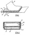
- FIG. 2 It is also possible to produce new types of packaging as illustrated in FIG. 2 and which comprise, on the one hand, a base (5) on which is likely to fit a cover (6).
- This base (5) comprises an internal partition (7) also based on a complex according to the invention.
- the chamber (8) there can be disposed a heating or cooling source constituted by a solid or liquid body whose thermal capacity is adequate for the desired purpose, this thermal capacity can be provided either by the mass heat of the body or by its latent heat. of merger or solidification.
Landscapes
- Engineering & Computer Science (AREA)
- Mechanical Engineering (AREA)
- Wrappers (AREA)
- Packages (AREA)
- Laminated Bodies (AREA)
- Packaging Of Annular Or Rod-Shaped Articles, Wearing Apparel, Cassettes, Or The Like (AREA)
- Packaging For Recording Disks (AREA)
Description
- La présente invention concerne un matériau isolant selon le preambule de la revendication 1. Un tel matériau est connu du document FR-A-2 278 592. L'invention concerne également un emballage protecteur isothermique réalisé à partir de ce matériau.
- A ce jour, de nombreuses matières sont utilisées pour réaliser des feuilles ou plaques isolantes utilisées notamment pour la réalisation d'emballages permettant d'assurer la protection isothermique de produits divers, tels que notamment des produits pharmaceutiques, alimentaires.. Parmi ces matériaux, on peut citer la laine de verre, la laine de roche, le polystyrène extrudé et expansé, les mousses de polyuréthane ou polyéthylène. Si de telles plaques peuvent être utilisées telles quelles, dans de nombreux cas, on a proposé de les associer sur l'une ou leurs deux faces à des feuilles réfléchissantes telles que par exemple une couche de papier aluminisé, une feuille d'aluminium, un film de PVC (ou similaire) métallisé sur une ou ses deux faces, notamment selon la technique de métallisation sous vide.
- En général, ces feuilles ou plaques sont mises en oeuvre en les disposant "en sandwich" entre deux parois, notamment dans le cas des glacières ou sacs isothermes en papier ou PVC destinés au transport d'aliments congelés, de produits pharmaceutiques,..
- De tels matériaux isolants donnent satisfaction pour la plupart des applications mais leur résistance thermique est fonction de leur épaisseur, ce qui conduit à des conditionnements de produits relativement volumineux, augmentent donc les coûts de production de tels emballages. Par ailleurs, les feuilles ou plaques isolantes de faible épaisseur actuellement commercialisées ne permettent une protection thermique que de durée limitée.
- Or on a trouvé, et c'est ce qui fait l'objet de la présente invention, qu'il était possible d'améliorer la résistance thermique de tels matériaux isolants dans de grandes proportions pour une épaisseur donnée et ce, sans pratiquement affecter les caractéristiques mécaniques des emballages réalisés à partir de tels matériaux.
- Selon l'invention, le matériau isolant composé d'une couche intermédiare isolante revêtue sur ses deux faces d'une feuille de matière refléchissante, est caractérisé par le fait que la couche intermédiaire isolante présente des perforations, régulièrement réparties sur ces surfaces et s'étendant sur toute son épaisseur, chaque perforation ayant une section qui est une fonction décroissante de l'épaisseur E du matériau, de manière à former un espace confiné entre les feuilles réfléchissantes externes, espace dans lequel l'air est immobile.
- Le rapport de la surface perforée à la surface totale sera adapté en fonction des caractéristiques mécaniques du matériau isolant utilisé. A titre d'exemple, pour un matériau en feuille ou plaque à base de polystyrène extrudé, ce rapport ne devra pas excéder 25%.
- Les feuilles réfléchissantes externes seront rapportées aux surfaces de la couche intermédiaire de manière connue, par exemple par collage voire même, en fonction de la structure interne de la couche isolante, par exemple dans le cas où cette couche isolante est à base d'une matière thermocollante, de réaliser cette association, par simple calendrage à chaud, provoquant une fusion superficielle de la couche isolante et par suite le collage des couches réfléchissantes externes.
- Comme matériau isolant constituant la couche interne, on utilisera tout matériau dont la structure permet de réaliser dans son épaisseur des perforations ayant une configuration stable.
- De préférence, on utilisera cependant comme couche intermédiaire isolante des matières plastiques cellulaires rigides telles que le polystryène extrudé et expandé, les mousses de polyuréthane ou de polyéthylène..
- L'invention et les avantages qu'elle apporte seront cependant mieux compris grâce aux exemples de réalisation donnés ci-après à titre indicatif et non limitatif, et qui sont illustrés par les schémas annexés dans lesquels:
- la figure 1 est une vue schématique en perspective éclatée montrant la structure d'un matériau isolant conforme à l'invention;
- la figure 2 montre un nouveau type d'emballage, qui fait également partie de l'invention, réalisé à partir d'un tel matériau.
- Si l'on se reporte aux schémas annexés et plus particulièrement à la figure 1, le matériau isolant conforme à l'invention se présente sous la forme d'une feuille ou plaque comportant d'une part une couche intermédiaire isolante (1), en général de faible épaisseur (comprise entre deux et douze millimètres), cette couche intermédiaire (1) étant revêtue sur ses deux faces de deux feuilles (2, 3) à base de matières réfléchissantes telles que par exemple un film métallisé sous vide (revêtement d'aluminium).
- Conformément à l'invention, la couche intermédiaire (2) comporte sur toute son épaisseur des perforations (4) régulièrement réparties et qui couvrent environ 25% de la surface totale de ladite couche intermédiaire (1). L'association des feuilles réfléchissantes (2, 3) externes à la couche intermédiaire (1) est réalisée par exemple par collage en prenant soin toutefois de ne pas obturer par un film de colle les orifices des perforations (4).
- Par rapport à un matériau similaire ne comportant pas de perforations internes, la résistance thermique globale de telles feuilles ou plaques se trouvent notablement améliorée comme le démontreront les trois exemples de réalisation qui suivent, exemples réalisés à partir de trois matériaux ayant respectivement:
- un λ de 0,027 W,
0,030 W,
0,035 W;
- pour les feuilles externes (2, 3) de feuilles réfléchissantes à base d'un film métallisé d'aluminium dont le pouvoir ε est de 0,04 et correspond à celui d'aluminium poli.
- Les trois matériaux conformes à l'invention se différencient par leur épaisseur E qui est respectivement de trois millimètres, six millimètres et dix millimètres.
- Dans ces trois exemples, les perforations (4) se présentent sous la forme de conduits cylindriques dont les diamètres sont identiques et, couvrent une surface variable du matériau, étant donné que suivant sa résistance mécanique compte- tenu de la surface totale des épaisseurs relativement faibles de la couche interne (1), on obtient dans tous les cas des espaces confinés où l'air est immobile. Pour des matériaux de moindre épaisseur, il pourrait être envisagé d'avoir des perforations de plus grande section alors qu'en revanche, pour des matériaux de plus grande épaisseur, il sera nécessaire d'adapter cette section pour obtenir de tels espaces confinés où l'air est immobile.
- Des essais comparatifs de résistance thermique sont réalisés pour des complexes isolants ne comportant pas de perforations et des complexes conformes à l'invention comportant des perforations couvrant plus ou moins 25% de la surface totale.
- Ces essais sont réalisés à partir de trois isolants (respectivement corps n°1, n°2, n°3), l'âme (1) du corps n°1 ayant un coefficient de conductivité de 0,029 W/m°C, les âmes des corps n°2 et 3 ayant des coefficients de conductivité de 0,030 et 0,035 W/m°C.
- Les résistances thermiques des différents complexes sont données par les relations suivantes:
- dans le cas de la conduction R =

- dans le cas de la connection et du rayonnement
- Rappelons que le λ (lambda) moyen de l'air immobile est de 0,025 W/m°C aux températures considérées. Dans ces conditions, la valeur du coefficient d'échange superficiel est donnée par la relation:

Voici le tableau donnant les résultats.
- On Constate donc grâce au matériau conforme à l'invention, que la résistance thermique globale est notablement améliorée et ce, d'autant plus que le complexe est de faible épaisseur.
- Grâce à de tels matériaux, il est possible de réaliser, notamment dans le cas de complexes de faible épaisseur, des emballages isothermes se présentant sous la forme de sachets ou enveloppes.
- Il est également possible de réaliser de nouveaux types d'emballages tels qu'illustrés à la figure 2 et qui comportent, d'une part, une base (5) sur laquelle est susceptible de s'emboiter un couvercle (6). Cette base (5) comporte une cloison interne (7) également à base d'un complexe conforme à l'invention. Dans la chambre (8), peut être disposée une source chauffante ou refroidissante constituée par un corps solide ou liquide dont la capacité thermique est adéquate au but recherché, cette capacité thermique pouvant être fournie soit par la chaleur massique du corps soit par sa chaleur latente de fusion ou de solidification.
- L'emploi combiné de ce type d'emballage avec une pochette réalisée avec le même matériau et munie d'une fermeture excluant tout échange entre l'air intérieur et l'atmosphère ambiante, permet de réaliser une double isolation du contenu de l'emballage intérieur et de le soustraire pendant un temps déterminé aux variations de la température de l'atmosphère, puisque le produit et son emballage, que l'on peut appeler "primaire", sont maintenus dans un milieu à température constante par suite de la présence et de l'action de la capacité thermique.
- Les exemples qui précèdent montrent bien les avantages apportés par l'invention.

T exprimant les températures des parois en °K.
Claims (5)
Priority Applications (1)
| Application Number | Priority Date | Filing Date | Title |
|---|---|---|---|
| AT89420013T ATE63091T1 (de) | 1988-01-14 | 1989-01-13 | Isolierendes material und von einem solchen material angefertigte isothermische schutzverpackung. |
Applications Claiming Priority (2)
| Application Number | Priority Date | Filing Date | Title |
|---|---|---|---|
| FR8800521 | 1988-01-14 | ||
| FR8800521A FR2625980B1 (fr) | 1988-01-14 | 1988-01-14 | Materiau isolant et emballage protecteur isothermique realise a partir d'un tel materiau |
Publications (2)
| Publication Number | Publication Date |
|---|---|
| EP0324702A1 EP0324702A1 (fr) | 1989-07-19 |
| EP0324702B1 true EP0324702B1 (fr) | 1991-05-02 |
Family
ID=9362413
Family Applications (1)
| Application Number | Title | Priority Date | Filing Date |
|---|---|---|---|
| EP89420013A Expired - Lifetime EP0324702B1 (fr) | 1988-01-14 | 1989-01-13 | Matériau isolant et emballage protecteur isothermique réalisé à partir d'un tel matériau |
Country Status (5)
| Country | Link |
|---|---|
| EP (1) | EP0324702B1 (fr) |
| AT (1) | ATE63091T1 (fr) |
| DE (1) | DE68900064D1 (fr) |
| FR (1) | FR2625980B1 (fr) |
| WO (1) | WO1989006628A1 (fr) |
Families Citing this family (2)
| Publication number | Priority date | Publication date | Assignee | Title |
|---|---|---|---|---|
| SE9603743L (sv) * | 1996-10-14 | 1998-02-09 | Tommy Wikstroem | Frysskyddsanordning och förfarande för att skydda livsmedel i frysutrymmen mot frysskador |
| RU2013112876A (ru) * | 2010-08-23 | 2014-09-27 | Нестек С.А. | Упаковка для мороженого |
Family Cites Families (6)
| Publication number | Priority date | Publication date | Assignee | Title |
|---|---|---|---|---|
| FR1043493A (fr) * | 1951-10-05 | 1953-11-09 | Récipient calorifuge | |
| FR1192889A (fr) * | 1957-03-14 | 1959-10-29 | Matériau d'emballage et de présentation et ses applications | |
| FR1252777A (fr) * | 1959-12-23 | 1961-02-03 | Feuille de matière d'emballage et emballages constitués avec une telle feuille | |
| DE6750190U (de) * | 1968-06-22 | 1969-01-02 | Papierfabrik G M B H Vorm Brue | Aus mehreren schichten bestehende verbundstoffbahn bzw. -platte |
| FR2278592A1 (fr) * | 1974-07-19 | 1976-02-13 | Leha Handels Gmbh Et Co | Procede pour la fabrication d'emballages calorifuges |
| SE447094B (sv) * | 1984-04-02 | 1986-10-27 | Lejondahl Lars Erik | Termiskt isolerad behallare |
-
1988
- 1988-01-14 FR FR8800521A patent/FR2625980B1/fr not_active Expired - Fee Related
-
1989
- 1989-01-13 AT AT89420013T patent/ATE63091T1/de not_active IP Right Cessation
- 1989-01-13 DE DE8989420013T patent/DE68900064D1/de not_active Expired - Fee Related
- 1989-01-13 WO PCT/FR1989/000008 patent/WO1989006628A1/fr not_active Ceased
- 1989-01-13 EP EP89420013A patent/EP0324702B1/fr not_active Expired - Lifetime
Also Published As
| Publication number | Publication date |
|---|---|
| FR2625980B1 (fr) | 1990-06-15 |
| FR2625980A1 (fr) | 1989-07-21 |
| WO1989006628A1 (fr) | 1989-07-27 |
| DE68900064D1 (de) | 1991-06-06 |
| EP0324702A1 (fr) | 1989-07-19 |
| ATE63091T1 (de) | 1991-05-15 |
Similar Documents
| Publication | Publication Date | Title |
|---|---|---|
| FR3040210B1 (fr) | Ensemble modulaire pour stockeur ou batterie | |
| EP1039211A3 (fr) | Méthode pour isoler récipient cryogénique | |
| FR3040211A1 (fr) | Ensemble et panneau articule, pour une isolation thermique | |
| FR2801367A1 (fr) | Complexe tubulaire isolant pour conduites coaxiales | |
| FR2616377A1 (fr) | Film a bulles d'air et isolant thermique anti-feu | |
| WO1989006628A1 (fr) | Materiau isolant et emballage protecteur isothermique realise a partir d'un tel materiau | |
| WO1986000219A1 (fr) | Perfectionnement aux complexes thermiques | |
| JPH0886394A (ja) | 真空断熱材及びその製造方法 | |
| FR2589447A3 (fr) | Sac d'isolation thermique pour l'emballage sous vide de micropoudres | |
| EP0990596B1 (fr) | Film à base de polyolefine pour former un emballage par pliage | |
| FR2911122A1 (fr) | Caisse isotherme a enveloppe metalisee en mousse a cellules fermees | |
| WO2017093691A1 (fr) | Piece isolante metallique tridimensionnelle | |
| FR3044739A1 (fr) | Piece isolante mecanique | |
| FR2553860A1 (fr) | Tube flexible utilisable notamment pour le transport de fluides caloporteurs ou frigorifiques | |
| EP3338020B1 (fr) | Ensemble et panneau articulé, a portions intermédiaires de positionnement, pour une isolation thermique | |
| FR2748736A1 (fr) | Conditionnements d'echantillons biologiques | |
| JPH11309069A (ja) | 電気湯沸かし器 | |
| US20240262077A1 (en) | Packaging materials with sealed edges and packaging systems | |
| FR3040212A1 (fr) | Ensemble isolant thermique et structure isolee par cet ensemble | |
| EP3301040B1 (fr) | Dispositif d'isolation thermique | |
| EP0132477B1 (fr) | Enceinte tubulaire à vide pour panneaux d'isolation thermique et acoustique | |
| CH688089A5 (fr) | Emballage isothermique. | |
| EP4296195A1 (fr) | Caisse isotherme triple isolation | |
| WO2016151214A1 (fr) | Dipositif pour le transport d'un produit sur une faible duree a une temperature garantie et constante | |
| FR2481785A1 (fr) | Surfaces pour capteur solaire |
Legal Events
| Date | Code | Title | Description |
|---|---|---|---|
| PUAI | Public reference made under article 153(3) epc to a published international application that has entered the european phase |
Free format text: ORIGINAL CODE: 0009012 |
|
| AK | Designated contracting states |
Kind code of ref document: A1 Designated state(s): AT BE CH DE ES FR GB GR IT LI LU NL SE |
|
| 17P | Request for examination filed |
Effective date: 19891110 |
|
| 17Q | First examination report despatched |
Effective date: 19900213 |
|
| GRAA | (expected) grant |
Free format text: ORIGINAL CODE: 0009210 |
|
| AK | Designated contracting states |
Kind code of ref document: B1 Designated state(s): AT BE CH DE ES FR GB GR IT LI LU NL SE |
|
| PG25 | Lapsed in a contracting state [announced via postgrant information from national office to epo] |
Ref country code: IT Free format text: LAPSE BECAUSE OF FAILURE TO SUBMIT A TRANSLATION OF THE DESCRIPTION OR TO PAY THE FEE WITHIN THE PRE;WARNING: LAPSES OF ITALIAN PATENTS WITH EFFECTIVE DATE BEFORE 2007 MAY HAVE OCCURRED AT ANY TIME BEFORE 2007. THE CORRECT EFFECTIVE DATE MAY BE DIFFERENT FROM THE ONE RECORDED.SCRIBED TIME-LIMIT Effective date: 19910502 Ref country code: GR Free format text: LAPSE BECAUSE OF FAILURE TO SUBMIT A TRANSLATION OF THE DESCRIPTION OR TO PAY THE FEE WITHIN THE PRESCRIBED TIME-LIMIT Effective date: 19910502 Ref country code: ES Free format text: THE PATENT HAS BEEN ANNULLED BY A DECISION OF A NATIONAL AUTHORITY Effective date: 19910502 Ref country code: SE Effective date: 19910502 Ref country code: GB Effective date: 19910502 Ref country code: AT Effective date: 19910502 Ref country code: NL Effective date: 19910502 |
|
| REF | Corresponds to: |
Ref document number: 63091 Country of ref document: AT Date of ref document: 19910515 Kind code of ref document: T |
|
| REF | Corresponds to: |
Ref document number: 68900064 Country of ref document: DE Date of ref document: 19910606 |
|
| NLV1 | Nl: lapsed or annulled due to failure to fulfill the requirements of art. 29p and 29m of the patents act | ||
| GBV | Gb: ep patent (uk) treated as always having been void in accordance with gb section 77(7)/1977 [no translation filed] | ||
| PG25 | Lapsed in a contracting state [announced via postgrant information from national office to epo] |
Ref country code: LU Free format text: LAPSE BECAUSE OF NON-PAYMENT OF DUE FEES Effective date: 19920131 |
|
| PLBE | No opposition filed within time limit |
Free format text: ORIGINAL CODE: 0009261 |
|
| STAA | Information on the status of an ep patent application or granted ep patent |
Free format text: STATUS: NO OPPOSITION FILED WITHIN TIME LIMIT |
|
| 26N | No opposition filed | ||
| PGFP | Annual fee paid to national office [announced via postgrant information from national office to epo] |
Ref country code: DE Payment date: 19970121 Year of fee payment: 9 |
|
| PGFP | Annual fee paid to national office [announced via postgrant information from national office to epo] |
Ref country code: CH Payment date: 19970203 Year of fee payment: 9 |
|
| PGFP | Annual fee paid to national office [announced via postgrant information from national office to epo] |
Ref country code: BE Payment date: 19970217 Year of fee payment: 9 |
|
| PG25 | Lapsed in a contracting state [announced via postgrant information from national office to epo] |
Ref country code: CH Free format text: LAPSE BECAUSE OF NON-PAYMENT OF DUE FEES Effective date: 19980131 Ref country code: LI Free format text: LAPSE BECAUSE OF NON-PAYMENT OF DUE FEES Effective date: 19980131 Ref country code: BE Free format text: LAPSE BECAUSE OF NON-PAYMENT OF DUE FEES Effective date: 19980131 |
|
| BERE | Be: lapsed |
Owner name: LIVRATEL Effective date: 19980131 |
|
| REG | Reference to a national code |
Ref country code: CH Ref legal event code: PL |
|
| PG25 | Lapsed in a contracting state [announced via postgrant information from national office to epo] |
Ref country code: DE Free format text: LAPSE BECAUSE OF NON-PAYMENT OF DUE FEES Effective date: 19981001 |
|
| PGFP | Annual fee paid to national office [announced via postgrant information from national office to epo] |
Ref country code: FR Payment date: 20000127 Year of fee payment: 12 |
|
| PG25 | Lapsed in a contracting state [announced via postgrant information from national office to epo] |
Ref country code: FR Free format text: LAPSE BECAUSE OF NON-PAYMENT OF DUE FEES Effective date: 20010928 |
|
| REG | Reference to a national code |
Ref country code: FR Ref legal event code: ST |