EP0324708A2 - Procédé et dispositif pour mesurer des vibrations - Google Patents
Procédé et dispositif pour mesurer des vibrations Download PDFInfo
- Publication number
- EP0324708A2 EP0324708A2 EP89630007A EP89630007A EP0324708A2 EP 0324708 A2 EP0324708 A2 EP 0324708A2 EP 89630007 A EP89630007 A EP 89630007A EP 89630007 A EP89630007 A EP 89630007A EP 0324708 A2 EP0324708 A2 EP 0324708A2
- Authority
- EP
- European Patent Office
- Prior art keywords
- predetermined
- probe
- beams
- component
- length
- Prior art date
- Legal status (The legal status is an assumption and is not a legal conclusion. Google has not performed a legal analysis and makes no representation as to the accuracy of the status listed.)
- Granted
Links
Images

Classifications
-
- G—PHYSICS
- G01—MEASURING; TESTING
- G01D—MEASURING NOT SPECIALLY ADAPTED FOR A SPECIFIC VARIABLE; ARRANGEMENTS FOR MEASURING TWO OR MORE VARIABLES NOT COVERED IN A SINGLE OTHER SUBCLASS; TARIFF METERING APPARATUS; MEASURING OR TESTING NOT OTHERWISE PROVIDED FOR
- G01D5/00—Mechanical means for transferring the output of a sensing member; Means for converting the output of a sensing member to another variable where the form or nature of the sensing member does not constrain the means for converting; Transducers not specially adapted for a specific variable
- G01D5/26—Mechanical means for transferring the output of a sensing member; Means for converting the output of a sensing member to another variable where the form or nature of the sensing member does not constrain the means for converting; Transducers not specially adapted for a specific variable characterised by optical transfer means, i.e. using infrared, visible, or ultraviolet light
- G01D5/268—Mechanical means for transferring the output of a sensing member; Means for converting the output of a sensing member to another variable where the form or nature of the sensing member does not constrain the means for converting; Transducers not specially adapted for a specific variable characterised by optical transfer means, i.e. using infrared, visible, or ultraviolet light using optical fibres
-
- G—PHYSICS
- G01—MEASURING; TESTING
- G01H—MEASUREMENT OF MECHANICAL VIBRATIONS OR ULTRASONIC, SONIC OR INFRASONIC WAVES
- G01H9/00—Measuring mechanical vibrations or ultrasonic, sonic or infrasonic waves by using radiation-sensitive means, e.g. optical means
Definitions
- This invention relates to interferometric measuring systems and more particularly to optical measuring arrangements and matters using interferometers with common optical paths.
- Fiber optic interferometers of the prior art include those characterized as modified Mach-Zehnder or Twyman-Green interferometers.
- these interferometers use light from a coherent source split into two optical beams.
- One of these beams constitutes a reference beam and traverses an optical path of a fixed length.
- the other beam constitues a probe beam and is guided along an optical path whose length is altered by the movement of an external object or workpiece being measured.
- the reference and probe beams are subsequently coherently recombined to produce an interference pattern indicative of the vibration or dynamic distortion of the mechanical element.
- Heterodyne optical interferometers are also well known in the art. These devices are similar to basic Mach-Zehnder and Twyman-Green interferometers but are modified to include an optical modulator which shifts the optical frequency of the reference and/or probe beam. As in the basic Mach-Zehnder or Twyman-Green interferometers, the optical path length of the probe beam is altered by the vibrating external object. The reference and probe beams are again subsequently recombined, yielding a frequency modulated (FM) beam with a carrier frequency equal to the frequency of the optical modulator and deviations from the carrier frquency caused by the vibration or dynamic distortion of the external object. The deviations which are caused by the motion of the external object are then extracted by conventional FM demodulation techniques.
- FM frequency modulated
- the reference and probe beams are usually guided along optical paths that include separate optical fibers.
- This configuration ensures that a truly stationary reference wavefront is used for comparison with the unknown Doppler shifted wavefront returning from the object.
- the optical fibers act as microphones in picking up environmental noise.
- This environmental noise signal is comprised of unwanted Doppler shifts due to environmental vibrations and attendant slight variations in the refractive index of the optical fiber carrying the probe or reference beam, and is added to the measured vibration signal from the object the motion of which is being measured, resulting in a distortion of the actual vibration frequency and amplitude signature imposed onto the returning light beam.
- the above zone has a finite area which exhibits surface irregularities having magnitudes capable of distorting the wavefront of the returning combined beam even when the object surface is of a very high surface quality, so that the remainder of the combined beam is scattered to a certain degree during its reflection from the above zone and forms a speckle pattern that includes bright and dark speckles due to interference in the returning combined beam.
- the above location is situated at the bright speckle; when it is not, there occurs a signal dropout due to the low or non-existent intensity of returning light at the above location due to its alignment with the dark speckle.
- Still another object of the present invention is so to develop the method of the type here under consideration as to virtually assure that reliable measurement results are obtained in spite of the existence of the speckle pattern.
- a concomitant object of the present invention is to devise a measuring arrangement capable of performing the method of the above type.
- An additional object of the present invention is to design the above measuring arrangement in such a manner as to present reliable measuring results regardless of the position of the aforementioned location relative to the speckle pattern.
- one feature of the present invention resides in a method of measuring the movement of a predetermined zone of a surface of a vibrating object, which method comprises the steps of generating a laser beam having a predetermined coherence length; separating the laser beam into a probe beam and a reference beam; delaying the reference beam relative to the probe beam by a predetermined time interval sufficient for the probe beam to travel through a predetermined distance at least corresponding to the coherence length; combining the thus delayed reference beam with the probe beam to form a combination beam; subdividing the combination beam into a plurality of substantially equal component beams; conducting each of the component beams along a separate path to a location spaced from the predetermined zone substantially by one-half of the distance traveled by light in said predetermined time interval between the respective location and the predetermined zone; reflecting a predetermined portion of each of the component beams at the respective location back into the respective path; directing the remainder of each of the component beams from the respective location to the predetermined zone for
- the present invention is also directed to an arrangement for measuring the movement of a predetermined zone of a surface of a vibrating object.
- this arrangement comprises means for generating a laser beam having a predetermined coherence length; means for separating the laser beam into a probe beam and a reference beam; means for delaying the reference beam relative to the probe beam by a predetermined time interval sufficient for the probe beam to travel through a predetermined distance at least corresponding to the coherence length; means for combining the thus delayed reference beam with the probe beam to form a combination beam; means for subdividing the combination beam into a plurality of substantially equal component beams; means for conducting each of the component beams along a separate path to a location spaced from the predetermined zone substantially by one-half of the distance traveled by light in said predetermined time interval between the respective location and the predetermined zone; means for reflecting a predetermined portion of each of the component beams at the respective location back into the respective path; means for directing the remainder of each of the component beams from the respective location to the predetermined zone
- a particular advantage obtained from the use of the method and arrangement of the present invention is that there is a plurality of the locations at which the coherent interference of the returning part of the probe beam with the reflected portion of the reference beam takes place, so that it is highly unlikely if not impossible that all of these locations would be aligned with dark regions of the speckle pattern.
- the method and arrangement of the present invention virtually assure that there will be detection under all circumstances, so long as the above locations are situated within a predetermined distance range from the predetermined zone and the combination beams are aimed at this zone.
- the measuring arrangement 10 includes a laser source 11, such as a laser diode marketed under the designation Sharp LT023MC which operates at a wavelength of 780 nanometers.
- a laser source 11 such as a laser diode marketed under the designation Sharp LT023MC which operates at a wavelength of 780 nanometers.
- the laser source 11 issues a laser beam 12 having a relatively short coherence length.
- the laser beam 12 enters a beam splitting device 13, which may include a fiber optic coupler, a preceding focusing lens, and subsequent collimating lenses, and which splits the laser beam 12 into two substantially equal partial beams 14 and 15 that are coherent with one another.
- the partial beam 14 is shown to be directed onto a modulator 16, especially an acousto-optic modulator or Bragg cell that is commercially available, for instance, as a Hoya A-100 modulator.
- the modulator 16 downshifts the frequency of the partial beam 14 by, for example, approximately 75 MHZ.
- the partial beam 15 is shown to be directed onto a modulator 17 which is advantageously of the same construction as the modulator 16.
- the modulator 17 upshifts the frequency of the partial beam 15 by, for example, approximately 85 MHz, so that there is a 160 MHz difference between the frequencies of respective carrier-modulated laser beams 18 and 19 that emerge from the respective modulators 16 and 17.
- the above-mentioned frequencies and modulating frequncy distribution which have been used in a practical embodiment of the present invention are not critical and may be changed either to change the frequency difference, or to keep it and change the amounts by which the two modulators 16 and 17 contribute to this difference, ultimately to the extent that only one of the modulators 16 and 17 is being used and no carrier modulation is imposed on the other partial beam 15 or 14.
- both of the modulators 16 and 17 may be omitted if it is not desired to impose carrier modulation on the partial beams 14 and 15.
- the carrier-modulated partial beams 18 and 19 (and/or the unmodulated partial beams 14 and 15) are focused by respective lenses 20 and 21 into respective optical fibers or fiber sections 22 and 23 which are shown to lead from one side to a 3 x 3 fiber-optic coupler 24.
- the fiber section 22 has a predetermined length L1
- the fiber section 23 has a length L2, the length L2 exceeding the length L1 by a distance that at least corresponds to but preferably exceeds the aforementioned coherence length.
- any region of the partial beam propagating in the optical fiber section 23 will reach the fiber-optic coupler 24 a predetermined time interval, which corresponds to the transit time of light through the aforementioned distance, later than the corresponding coherent region of the partial beam propagating in the optical fiber section 22, so that the light in such regions will be out of coherence with one another by the time such regions reach the coupler 24.
- these partial beams are incoherently combined with one another, without losing their identites as a probe beam (from the fiber 22) and reference beam (from the fiber 23), and the combined beam is then subdivided in three substantially equal component beams which leave the coupler 24 at the other side thereof and are launched into respective optical fibers 25, 26 and 27.
- the optical fibers 25, 26 and 27 are preferably contained in a single optical cable. When either one of the component beams reaches an end face of the respective fiber 25, 26 and 27, a portion thereof will be reflected from this end face (or from a coating applied to this end face) back into the respective fiber 25, 26 or 27 for propagation back toward the coupler 24.
- the remainder of the respective component beam issues from the downstream end of the respective fiber 25, 26 or 27, and is collimated by a respective lens 28, 29 or 30 to form a respective collimated component beam remainder 31, 32 or 33, and the collimated component beam remainders are focused by a shared lens 34 onto a region or zone 35 of a surface 36 or an object whose vibrations are to be measured.
- At least a part of the light that reaches the zone 35 is returned back, usually as scattered radiation that, as is well known, forms a speckle pattern at the plane of the end faces of the fibers 25, 26 and 27.
- the thus returned light reaches the end face of the respective fiber, it interferes with any light with which it is coherent. This means that the probe beam part of the returning light interferes with the reference beam part of the reflected portion of the combined beam in the associated optical fiber section 25, 26 or 27.
- the returning probe beam part stemming from one of the optical fiber sections, such as 25, could also interfere with reference beam part of the reflected portion in the other optical fiber sections, such as 26 and 27. This could give erroneous results.
- the optical fiber sections 25, 26 and 27 have different lengths L3, L4 and L5, the lengths L4 and L5 being longer than the length L3 and than one another, as indicated by a single loop in the fiber section 26 and by a double loop in the fiber section 27, and being at least in a predetermined ratio to the aforementioned distance L2 - L1. According to the invention, this ratio advantageously is an integral multiple of 3.
- the returning light beams propagating in the fiber optic sections 25, 26 and 27 eventually reach the 3 x 3 optical coupler where the component beams are recombined with one another and a portion of the thus recombined light beam is conducted through another fiber section to a photodetector 51 which converts the light signal into an electrical signal, in a well known manner.
- This electrical signal is then demodulated in a demodulator 52 of any known construction, particularly an FM demodulator, to obtain an indication of the vibratory movement of the zone 35.
- the locations of the end faces of the fiber sections 25, 26 and 27 are spaced from the zone 35 by substantially one-half of the distance traveled by light during the predetermined time interval in the medium or media situated between these end faces and the zone 35.
- the reference numeral 38 designates a sheath which accommodates the downstream end portions of the fiber sections 25, 26 and 27 and is connected to a housing or wand 39.
- a holding member 40 is held substantially centrally in the housing 39 by respective webs 41 and confines the extreme end portions of the fiber sections in the positions thereof which are illustrated in Figure 3, that is, at the corners of an isosceles triangle.
- the light emanating from the end faces of the fiber sections is focused by a shared lens 42 mounted in the housing 39 onto the zone 35 of the surface 36 of the vibrating object 37.
- the spots formed by the combination beam remainders issuing from the fiber sections 25, 26 and 27 usually do not coincide, but they are still close enough to one another to assure that the vibrations of one and the same zone 35 are being measured.
- multimode optical fiber exhibiting a limited number of modes, such as that having a core diameter of approximately 10 microns, in the arrangement of the present invention.
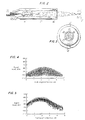
- the reason for this will become apparent from a comparison of Figures 4 and 5 of the drawing with one another. More particularly, if a single mode fiber were used, the signal level would undergo considerable changes in dependence on the path length mismatch or difference between the arms of the interferometer. This is shown in Figure 4 for a situation where a GO-1000 laser diode has been used as the laser source, with -108 dBm being the approximate noise limit of the detection electronics.
- a multi-mode fiber is being used in the arms of the interferometer, the characteristic fringe visibility profile of the laser is repeated several times.
Landscapes
- Physics & Mathematics (AREA)
- General Physics & Mathematics (AREA)
- Measurement Of Mechanical Vibrations Or Ultrasonic Waves (AREA)
- Instruments For Measurement Of Length By Optical Means (AREA)
- Length Measuring Devices By Optical Means (AREA)
- Investigating Or Analyzing Materials By The Use Of Ultrasonic Waves (AREA)
Priority Applications (1)
| Application Number | Priority Date | Filing Date | Title |
|---|---|---|---|
| AT89630007T ATE104430T1 (de) | 1988-01-11 | 1989-01-10 | Verfahren und geraet zur messung von vibrationen. |
Applications Claiming Priority (2)
| Application Number | Priority Date | Filing Date | Title |
|---|---|---|---|
| US07/142,889 US4892406A (en) | 1988-01-11 | 1988-01-11 | Method of and arrangement for measuring vibrations |
| US142889 | 1999-07-08 |
Publications (3)
| Publication Number | Publication Date |
|---|---|
| EP0324708A2 true EP0324708A2 (fr) | 1989-07-19 |
| EP0324708A3 EP0324708A3 (fr) | 1991-04-03 |
| EP0324708B1 EP0324708B1 (fr) | 1994-04-13 |
Family
ID=22501688
Family Applications (1)
| Application Number | Title | Priority Date | Filing Date |
|---|---|---|---|
| EP89630007A Expired - Lifetime EP0324708B1 (fr) | 1988-01-11 | 1989-01-10 | Procédé et dispositif pour mesurer des vibrations |
Country Status (6)
| Country | Link |
|---|---|
| US (1) | US4892406A (fr) |
| EP (1) | EP0324708B1 (fr) |
| JP (1) | JP2686124B2 (fr) |
| AT (1) | ATE104430T1 (fr) |
| DE (1) | DE68914472T2 (fr) |
| FI (1) | FI92958C (fr) |
Cited By (1)
| Publication number | Priority date | Publication date | Assignee | Title |
|---|---|---|---|---|
| US6545762B2 (en) | 2000-04-17 | 2003-04-08 | Logica Uk Limited | Method of investigating vibrations and an apparatus therefor |
Families Citing this family (114)
| Publication number | Priority date | Publication date | Assignee | Title |
|---|---|---|---|---|
| DE3916276A1 (de) * | 1989-05-19 | 1990-11-22 | Betr Forsch Inst Angew Forsch | Verfahren und vorrichtung zur interferometrischen detektion von oberflaechenverschiebungen bei festkoerpern |
| JPH03104842U (fr) * | 1990-02-06 | 1991-10-30 | ||
| IT1244170B (it) * | 1990-12-04 | 1994-07-08 | Cise Spa | Apparecchiatura laser per la misura della velocita' di un fluido. |
| US5166749A (en) * | 1991-05-22 | 1992-11-24 | Bio-Rad Laboratories | Step scanning technique for interferometer |
| JP3234353B2 (ja) * | 1993-06-15 | 2001-12-04 | 富士写真フイルム株式会社 | 断層情報読取装置 |
| US5493394A (en) * | 1994-05-25 | 1996-02-20 | The Boeing Company | Method and apparatus for use in measuring frequency difference between light signals |
| US5477324A (en) * | 1994-08-26 | 1995-12-19 | Georgia Tech Research Corporation | Method and apparatus for detecting surface wave vector dynamics using three beams of coherent light |
| DE19528676C2 (de) * | 1995-08-04 | 1997-05-22 | Zeiss Carl Jena Gmbh | Interferometeranordnung zur absoluten Distanzmessung |
| JPH11326653A (ja) * | 1998-05-15 | 1999-11-26 | Sony Corp | 光のコヒーレンス低減方法及びその装置、照明方法及びその装置、並びに、光ファイバーバンドル |
| US6246638B1 (en) * | 1999-03-30 | 2001-06-12 | Honeywell International Inc. | Fiber-optic vibration sensor based on frequency modulation of light-excited oscillators |
| US6325172B1 (en) | 2000-05-25 | 2001-12-04 | Pvt-Wrl, Llc | Geophone including laser interferometer |
| DE10031636B4 (de) * | 2000-06-29 | 2006-01-05 | Siemens Ag | Spektrometer |
| US9295391B1 (en) * | 2000-11-10 | 2016-03-29 | The General Hospital Corporation | Spectrally encoded miniature endoscopic imaging probe |
| DE10297689B4 (de) * | 2001-05-01 | 2007-10-18 | The General Hospital Corp., Boston | Verfahren und Gerät zur Bestimmung von atherosklerotischem Belag durch Messung von optischen Gewebeeigenschaften |
| US7355716B2 (en) * | 2002-01-24 | 2008-04-08 | The General Hospital Corporation | Apparatus and method for ranging and noise reduction of low coherence interferometry LCI and optical coherence tomography OCT signals by parallel detection of spectral bands |
| EP2319404B1 (fr) * | 2003-01-24 | 2015-03-11 | The General Hospital Corporation | Système et procédé pour identifier des tissus à l'aide d'interférométrie à faible cohérence |
| US8054468B2 (en) | 2003-01-24 | 2011-11-08 | The General Hospital Corporation | Apparatus and method for ranging and noise reduction of low coherence interferometry LCI and optical coherence tomography OCT signals by parallel detection of spectral bands |
| AU2004225188B2 (en) | 2003-03-31 | 2010-04-15 | The General Hospital Corporation | Speckle reduction in optical coherence tomography by path length encoded angular compounding |
| US7515626B2 (en) * | 2003-05-29 | 2009-04-07 | Novera Optics, Inc. | Light source capable of lasing that is wavelength locked by an injected light signal |
| EP2280258A3 (fr) | 2003-06-06 | 2015-09-02 | The General Hospital Corporation | Procédé et appareil pour une source de lumière à réglage de longueur d'onde |
| CN103293126B (zh) | 2003-10-27 | 2017-03-01 | 通用医疗公司 | 用于使用频域干涉测量法进行光学成像的方法和设备 |
| WO2005054780A1 (fr) | 2003-11-28 | 2005-06-16 | The General Hospital Corporation | Procede et appareil d'imagerie codee de maniere spectrale tridimensionnelle |
| AU2004320269B2 (en) | 2004-05-29 | 2011-07-21 | The General Hospital Corporation | Process, system and software arrangement for a chromatic dispersion compensation using reflective layers in optical coherence tomography (OCT) imaging |
| EP1771755B1 (fr) | 2004-07-02 | 2016-09-21 | The General Hospital Corporation | Sonde d'imagerie endoscopique comprenant des fibres double gaine |
| JP5053845B2 (ja) | 2004-08-06 | 2012-10-24 | ザ ジェネラル ホスピタル コーポレイション | 光学コヒーレンス断層撮影法を使用して試料中の少なくとも1つの位置を決定するための方法、システムおよびソフトウェア装置 |
| KR20070058523A (ko) * | 2004-08-24 | 2007-06-08 | 더 제너럴 하스피탈 코포레이션 | 혈관절편 영상화 방법 및 장치 |
| EP1793730B1 (fr) | 2004-08-24 | 2011-12-28 | The General Hospital Corporation | Ensemble procede, systeme et logiciel pour la détermination de module d 'élasticité |
| US7366376B2 (en) | 2004-09-29 | 2008-04-29 | The General Hospital Corporation | System and method for optical coherence imaging |
| EP1807722B1 (fr) * | 2004-11-02 | 2022-08-10 | The General Hospital Corporation | Dispositif rotationnel a fibres optiques, systeme optique pour imager un echantillon |
| US7388672B2 (en) * | 2004-11-19 | 2008-06-17 | Carl Ziess Meditec, Inc. | High efficiency balanced detection interferometer |
| EP2278266A3 (fr) * | 2004-11-24 | 2011-06-29 | The General Hospital Corporation | Interféromètre à chemin commun pour OCT endoscopique |
| EP1816949A1 (fr) * | 2004-11-29 | 2007-08-15 | The General Hospital Corporation | Ensembles, dispositifs, endoscopes, catheters et methodes d'imagerie optique permettant d'eclairer et de detecter simultanement plusieurs points sur un echantillon |
| WO2006116769A1 (fr) | 2005-04-28 | 2006-11-02 | The General Hospital Corporation | Systemes, procedes et agencements logiciels servant a evaluer des informations associees a une structure anatomique au moyen d'une technique de telemetrie de coherence optique |
| EP1886121A1 (fr) * | 2005-05-13 | 2008-02-13 | The General Hospital Corporation | Arrangements, systemes et procedes permettant d'obtenir une reflectrometrie de coherence optique du domaine spectral pour une detection sensible d'un echantillon chimique et biologique |
| WO2006130797A2 (fr) | 2005-05-31 | 2006-12-07 | The General Hospital Corporation | Systeme, procede et dispositif qui peuvent utiliser des techniques d'interferometrie d'heterodyne a codage spectral pour l'imagerie |
| ATE484727T1 (de) * | 2005-08-09 | 2010-10-15 | Gen Hospital Corp | Gerät und verfahren zur durchführung von polarisationsbasierter quadraturdemodulation bei optischer kohärenztomographie |
| JP6046325B2 (ja) | 2005-09-29 | 2016-12-14 | ザ ジェネラル ホスピタル コーポレイション | 漸次的に解像度を増加させて1以上の生物学的サンプルの観察及び分析のための方法及びその方法のための装置 |
| JP5203951B2 (ja) | 2005-10-14 | 2013-06-05 | ザ ジェネラル ホスピタル コーポレイション | スペクトル及び周波数符号化蛍光画像形成 |
| EP1971848B1 (fr) | 2006-01-10 | 2019-12-04 | The General Hospital Corporation | Systèmes et procédés de génération de données basés sur une ou plusieurs technique(s) d'endoscopie spectralement codées |
| EP2289396A3 (fr) | 2006-01-19 | 2011-04-06 | The General Hospital Corporation | Procédés et systèmes pour visualiser de manière optique des organes intracavitaires épithéliaux lors d'un balayage au faisceau |
| US8145018B2 (en) | 2006-01-19 | 2012-03-27 | The General Hospital Corporation | Apparatus for obtaining information for a structure using spectrally-encoded endoscopy techniques and methods for producing one or more optical arrangements |
| US20080002211A1 (en) * | 2006-01-20 | 2008-01-03 | The General Hospital Corporation | System, arrangement and process for providing speckle reductions using a wave front modulation for optical coherence tomography |
| WO2007084933A2 (fr) * | 2006-01-20 | 2007-07-26 | The General Hospital Corporation | Systemes et procedes pour produire une imagerie moleculaire endogene avec un eclairage mid-infrarouge |
| US7538859B2 (en) | 2006-02-01 | 2009-05-26 | The General Hospital Corporation | Methods and systems for monitoring and obtaining information of at least one portion of a sample using conformal laser therapy procedures, and providing electromagnetic radiation thereto |
| WO2007149601A2 (fr) * | 2006-02-01 | 2007-12-27 | The General Hospital Corporation | Appareil destiné à commander au moins l'une d'au moins deux sections d'au moins une fibre |
| JP5524487B2 (ja) | 2006-02-01 | 2014-06-18 | ザ ジェネラル ホスピタル コーポレイション | コンフォーマルレーザ治療手順を用いてサンプルの少なくとも一部分に電磁放射を放射する方法及びシステム。 |
| WO2007092911A2 (fr) | 2006-02-08 | 2007-08-16 | The General Hospital Corporation | procedes, dispositifs et systemes pour obtenir des informations associees a un prelevement anatomique utilisant la microscopie optique |
| EP1987318B1 (fr) | 2006-02-24 | 2015-08-12 | The General Hospital Corporation | Procédés et systèmes destinés à réaliser une tomographie par cohérence optique dans le domaine de fourier avec résolution angulaire |
| JP2009533076A (ja) * | 2006-03-01 | 2009-09-17 | ザ ジェネラル ホスピタル コーポレイション | 光吸収体をマクロファージに標的化することによるアテローム班の細胞特異的レーザー治療を提供するシステム及び方法 |
| WO2007118129A1 (fr) | 2006-04-05 | 2007-10-18 | The General Hospital Corporation | Procedes, dispositifs et systemes pour effectuer une imagerie de domaine de frequence optique d'un echantillon sensible a la polarisation |
| WO2007133961A2 (fr) | 2006-05-10 | 2007-11-22 | The General Hospital Corporation | Processus, agencements et systèmes pour obtenir une imagerie de domaine de fréquence d'un échantillon |
| US7782464B2 (en) | 2006-05-12 | 2010-08-24 | The General Hospital Corporation | Processes, arrangements and systems for providing a fiber layer thickness map based on optical coherence tomography images |
| WO2008016927A2 (fr) * | 2006-08-01 | 2008-02-07 | The General Hospital Corporation | Systèmes et procédés pour recevoir et/ou analyser des informations associées à un rayonnement électromagnétique |
| US7920271B2 (en) * | 2006-08-25 | 2011-04-05 | The General Hospital Corporation | Apparatus and methods for enhancing optical coherence tomography imaging using volumetric filtering techniques |
| EP2077753B1 (fr) * | 2006-09-12 | 2012-12-19 | The General Hospital Corporation | Appareil, sonde et procede destines a effectuer des evaluations de profondeur dans une structure anatomique |
| WO2008049118A2 (fr) | 2006-10-19 | 2008-04-24 | The General Hospital Corporation | Dispositif et procédé d'obtention et de fourniture d'informations d'image associées à au moins une portion d' échantillon et permettant de réaliser une telle portion |
| WO2008089406A2 (fr) | 2007-01-19 | 2008-07-24 | The General Hospital Corporation | Appareil et procédé pour contrôler la profondeur de télémétrie dans une imagerie de domaine de fréquence optique |
| US20080206804A1 (en) * | 2007-01-19 | 2008-08-28 | The General Hospital Corporation | Arrangements and methods for multidimensional multiplexed luminescence imaging and diagnosis |
| EP2662674A3 (fr) * | 2007-01-19 | 2014-06-25 | The General Hospital Corporation | Réflexion de disque rotatif pour balayage rapide de longueur d'onde de lumière à large bande dispersée |
| DE102007010389B4 (de) * | 2007-03-03 | 2011-03-10 | Polytec Gmbh | Vorrichtung zur optischen Vermessung eines Objekts |
| WO2008115965A1 (fr) * | 2007-03-19 | 2008-09-25 | The General Hospital Corporation | Appareil et methode de diagnostic non invasif d'une hemorragie interne |
| WO2008116010A1 (fr) * | 2007-03-19 | 2008-09-25 | The General Hospital Corporation | Système et procédé permettant un diagnostic non invasif du syndrome de compartiment, exemples de procédure d'imagerie de points par laser |
| EP2602651A3 (fr) * | 2007-03-23 | 2014-08-27 | The General Hospital Corporation | Procédés, agencements et appareil pour utiliser un laser à balayage de longueur d'ondes utilisant un balayage angulaire et des procédures de dispersion |
| WO2008121844A1 (fr) * | 2007-03-30 | 2008-10-09 | The General Hospital Corporation | Système et procédé pour fournir une imagerie à granularité laser en vue de détecter une plaque à risque |
| WO2008131082A1 (fr) | 2007-04-17 | 2008-10-30 | The General Hospital Corporation | Appareil et procédés de mesure des vibrations à l'aide de techniques d'endoscopie spectralement codées |
| US8115919B2 (en) * | 2007-05-04 | 2012-02-14 | The General Hospital Corporation | Methods, arrangements and systems for obtaining information associated with a sample using optical microscopy |
| JP5917803B2 (ja) * | 2007-07-31 | 2016-05-18 | ザ ジェネラル ホスピタル コーポレイション | 高速ドップラー光周波数領域撮像法のためのビーム走査パターンを放射するシステムおよび方法 |
| US8040608B2 (en) * | 2007-08-31 | 2011-10-18 | The General Hospital Corporation | System and method for self-interference fluorescence microscopy, and computer-accessible medium associated therewith |
| WO2009036453A1 (fr) * | 2007-09-15 | 2009-03-19 | The General Hospital Corporation | Appareil, support accessible par ordinateur et procédé de mesure de compositions chimiques et/ou moléculaires de plaques athéroscléreuses coronariennes dans des structures anatomiques |
| US20090131801A1 (en) * | 2007-10-12 | 2009-05-21 | The General Hospital Corporation | Systems and processes for optical imaging of luminal anatomic structures |
| WO2009059034A1 (fr) * | 2007-10-30 | 2009-05-07 | The General Hospital Corporation | Système et procédé permettant une détection de mode de gaine |
| US20090225324A1 (en) * | 2008-01-17 | 2009-09-10 | The General Hospital Corporation | Apparatus for providing endoscopic high-speed optical coherence tomography |
| US11123047B2 (en) | 2008-01-28 | 2021-09-21 | The General Hospital Corporation | Hybrid systems and methods for multi-modal acquisition of intravascular imaging data and counteracting the effects of signal absorption in blood |
| US9332942B2 (en) * | 2008-01-28 | 2016-05-10 | The General Hospital Corporation | Systems, processes and computer-accessible medium for providing hybrid flourescence and optical coherence tomography imaging |
| WO2009137701A2 (fr) * | 2008-05-07 | 2009-11-12 | The General Hospital Corporation | Système, procédé et support informatique permettant le suivi du mouvement des vaisseaux lors d'un examen en microscopie tridimensionnelle des artères coronaires |
| US8861910B2 (en) * | 2008-06-20 | 2014-10-14 | The General Hospital Corporation | Fused fiber optic coupler arrangement and method for use thereof |
| WO2010009136A2 (fr) * | 2008-07-14 | 2010-01-21 | The General Hospital Corporation | Appareil et procédés d'endoscopie couleur |
| JP5752040B2 (ja) * | 2008-09-11 | 2015-07-22 | ニコン・メトロロジー・エヌヴェ | 対チャープfmcwコヒーレントレーザレーダー用の小型の光ファイバ配置 |
| US8937724B2 (en) | 2008-12-10 | 2015-01-20 | The General Hospital Corporation | Systems and methods for extending imaging depth range of optical coherence tomography through optical sub-sampling |
| EP2382456A4 (fr) * | 2009-01-26 | 2012-07-25 | Gen Hospital Corp | Système, procédé et support accessible par ordinateur permettant de fournir une microscopie de super-résolution à large champ |
| JP6053284B2 (ja) | 2009-02-04 | 2016-12-27 | ザ ジェネラル ホスピタル コーポレイション | ハイスピード光学波長チューニング源の利用のための装置及び方法 |
| US9351642B2 (en) | 2009-03-12 | 2016-05-31 | The General Hospital Corporation | Non-contact optical system, computer-accessible medium and method for measurement at least one mechanical property of tissue using coherent speckle technique(s) |
| WO2011008822A2 (fr) | 2009-07-14 | 2011-01-20 | The General Hospital Corporation | Appareil, systèmes et procédés permettant de mesurer le débit et la pression à lintérieur dune cuve |
| EP2485641A4 (fr) * | 2009-10-06 | 2015-10-14 | Gen Hospital Corp | Appareil et procédés pour l'imagerie de cellules particulières dont les éosinophiles |
| US20110224541A1 (en) * | 2009-12-08 | 2011-09-15 | The General Hospital Corporation | Methods and arrangements for analysis, diagnosis, and treatment monitoring of vocal folds by optical coherence tomography |
| KR20130004326A (ko) | 2010-03-05 | 2013-01-09 | 더 제너럴 하스피탈 코포레이션 | 특정 해상도에서 적어도 하나의 해부학적 구조의 미세 영상을 제공하는 시스템, 방법 및 컴퓨터 접근 가능 매체 |
| US9069130B2 (en) | 2010-05-03 | 2015-06-30 | The General Hospital Corporation | Apparatus, method and system for generating optical radiation from biological gain media |
| US9795301B2 (en) | 2010-05-25 | 2017-10-24 | The General Hospital Corporation | Apparatus, systems, methods and computer-accessible medium for spectral analysis of optical coherence tomography images |
| WO2011149972A2 (fr) | 2010-05-25 | 2011-12-01 | The General Hospital Corporation | Systèmes, dispositifs, procédés, appareil et supports accessibles par ordinateur pour fournir une imagerie optique de structures et de compositions |
| US10285568B2 (en) | 2010-06-03 | 2019-05-14 | The General Hospital Corporation | Apparatus and method for devices for imaging structures in or at one or more luminal organs |
| JP5883018B2 (ja) | 2010-10-27 | 2016-03-09 | ザ ジェネラル ホスピタル コーポレイション | 少なくとも1つの血管内部の血圧を測定するための装置、システム、および方法 |
| JP6240064B2 (ja) | 2011-04-29 | 2017-11-29 | ザ ジェネラル ホスピタル コーポレイション | 散乱媒質の深さ分解した物理的及び/又は光学的特性を決定する方法 |
| WO2013013049A1 (fr) | 2011-07-19 | 2013-01-24 | The General Hospital Corporation | Systèmes, procédés, appareils et supports accessibles par ordinateur permettant de produire une compensation de dispersion en mode polarisation dans la tomographie à cohérence optique |
| EP2748587B1 (fr) | 2011-08-25 | 2021-01-13 | The General Hospital Corporation | Procédés et arrangements permettant de mettre en oeuvre des procédures de tomographie par cohérence micro-optique |
| WO2013066631A1 (fr) | 2011-10-18 | 2013-05-10 | The General Hospital Corporation | Appareil et procédés de production et/ou d'utilisation de retard(s) optique(s) de recirculation |
| WO2013148306A1 (fr) | 2012-03-30 | 2013-10-03 | The General Hospital Corporation | Système d'imagerie, procédé et fixation distale permettant une endoscopie à champ de vision multidirectionnel |
| US11490797B2 (en) | 2012-05-21 | 2022-11-08 | The General Hospital Corporation | Apparatus, device and method for capsule microscopy |
| EP2888616A4 (fr) | 2012-08-22 | 2016-04-27 | Gen Hospital Corp | Système, procédé et support accessible par ordinateur pour fabriquer des endoscopes miniatures à l'aide d'une lithographie douce |
| WO2014120791A1 (fr) | 2013-01-29 | 2014-08-07 | The General Hospital Corporation | Appareil, systèmes et procédés pour donner des informations sur la valvule aortique |
| US11179028B2 (en) | 2013-02-01 | 2021-11-23 | The General Hospital Corporation | Objective lens arrangement for confocal endomicroscopy |
| US10478072B2 (en) | 2013-03-15 | 2019-11-19 | The General Hospital Corporation | Methods and system for characterizing an object |
| US9784681B2 (en) | 2013-05-13 | 2017-10-10 | The General Hospital Corporation | System and method for efficient detection of the phase and amplitude of a periodic modulation associated with self-interfering fluorescence |
| US11452433B2 (en) | 2013-07-19 | 2022-09-27 | The General Hospital Corporation | Imaging apparatus and method which utilizes multidirectional field of view endoscopy |
| WO2015010133A1 (fr) | 2013-07-19 | 2015-01-22 | The General Hospital Corporation | Détermination de mouvement oculaire au moyen d'une imagerie de la rétine avec rétroaction r un mouvement de l'œil par imagerie de la rétine et fournir des informations en retour pour l'acquisition de signaux venant de la rétine |
| US9668652B2 (en) | 2013-07-26 | 2017-06-06 | The General Hospital Corporation | System, apparatus and method for utilizing optical dispersion for fourier-domain optical coherence tomography |
| US9733460B2 (en) | 2014-01-08 | 2017-08-15 | The General Hospital Corporation | Method and apparatus for microscopic imaging |
| US10736494B2 (en) | 2014-01-31 | 2020-08-11 | The General Hospital Corporation | System and method for facilitating manual and/or automatic volumetric imaging with real-time tension or force feedback using a tethered imaging device |
| WO2015153982A1 (fr) | 2014-04-04 | 2015-10-08 | The General Hospital Corporation | Appareil et procédé de commande de la propagation et/ou de la transmission d'un rayonnement électromagnétique dans un ou des guides d'ondes flexibles |
| ES2907287T3 (es) | 2014-07-25 | 2022-04-22 | Massachusetts Gen Hospital | Aparato para imagenología y diagnóstico in vivo |
| JP7723897B2 (ja) * | 2021-09-15 | 2025-08-15 | オムロン株式会社 | 光干渉測距センサ |
| JP7751788B2 (ja) | 2021-09-15 | 2025-10-09 | オムロン株式会社 | 光干渉測距センサ |
| JP7832591B2 (ja) | 2022-03-11 | 2026-03-18 | オムロン株式会社 | 光干渉測距センサ |
| JP2023132668A (ja) | 2022-03-11 | 2023-09-22 | オムロン株式会社 | 光干渉測距センサ |
| JP2023132738A (ja) | 2022-03-11 | 2023-09-22 | オムロン株式会社 | 光干渉測距センサ |
Family Cites Families (7)
| Publication number | Priority date | Publication date | Assignee | Title |
|---|---|---|---|---|
| US4146373A (en) * | 1977-12-23 | 1979-03-27 | Owens-Corning Fiberglas Corporation | Bushing construction |
| US4356395A (en) * | 1979-07-06 | 1982-10-26 | The Boeing Company | Digital fiber optic sensor system |
| FR2476326A1 (fr) * | 1980-02-20 | 1981-08-21 | Cilas | Dispositif pour determiner la position angulaire d'une cible eclairee par des impulsions lumineuses |
| JPS59143908A (ja) * | 1983-02-07 | 1984-08-17 | Mitsutoyo Mfg Co Ltd | 表面粗さ検出装置 |
| US4743113A (en) * | 1985-08-29 | 1988-05-10 | Western Atlas International, Inc. | Optical fiber interferometer network |
| US4627731A (en) * | 1985-09-03 | 1986-12-09 | United Technologies Corporation | Common optical path interferometric gauge |
| US4748686A (en) * | 1986-10-15 | 1988-05-31 | United Technologies Corporation | Coherence multiplexed optical position transducer |
-
1988
- 1988-01-11 US US07/142,889 patent/US4892406A/en not_active Expired - Fee Related
-
1989
- 1989-01-10 DE DE68914472T patent/DE68914472T2/de not_active Expired - Fee Related
- 1989-01-10 JP JP1003617A patent/JP2686124B2/ja not_active Expired - Lifetime
- 1989-01-10 AT AT89630007T patent/ATE104430T1/de not_active IP Right Cessation
- 1989-01-10 EP EP89630007A patent/EP0324708B1/fr not_active Expired - Lifetime
- 1989-01-10 FI FI890120A patent/FI92958C/fi not_active IP Right Cessation
Cited By (1)
| Publication number | Priority date | Publication date | Assignee | Title |
|---|---|---|---|---|
| US6545762B2 (en) | 2000-04-17 | 2003-04-08 | Logica Uk Limited | Method of investigating vibrations and an apparatus therefor |
Also Published As
| Publication number | Publication date |
|---|---|
| FI92958C (fi) | 1995-01-25 |
| JP2686124B2 (ja) | 1997-12-08 |
| JPH02196912A (ja) | 1990-08-03 |
| FI890120A0 (fi) | 1989-01-10 |
| US4892406A (en) | 1990-01-09 |
| ATE104430T1 (de) | 1994-04-15 |
| EP0324708B1 (fr) | 1994-04-13 |
| FI890120A7 (fi) | 1989-07-12 |
| EP0324708A3 (fr) | 1991-04-03 |
| DE68914472T2 (de) | 1994-07-28 |
| FI92958B (fi) | 1994-10-14 |
| DE68914472D1 (de) | 1994-05-19 |
Similar Documents
| Publication | Publication Date | Title |
|---|---|---|
| EP0324708B1 (fr) | Procédé et dispositif pour mesurer des vibrations | |
| EP0241512B1 (fr) | Jauge interferometrique a chemin optique commun | |
| US7557930B2 (en) | Bessel beam interferometer and measurement method | |
| US5349440A (en) | Interferometric laser profilometer including a multimode laser diode emitting a range of stable wavelengths | |
| KR100854259B1 (ko) | 간섭 측정 장치 | |
| JPH02236103A (ja) | ロボット端部作動体および工具用の集積光ファイバ結合近接センサ | |
| US5909279A (en) | Ultrasonic sensor using short coherence length optical source, and operating method | |
| US5477324A (en) | Method and apparatus for detecting surface wave vector dynamics using three beams of coherent light | |
| US6243168B1 (en) | Dynamic optical micrometer | |
| US6147755A (en) | Dynamic optical phase state detector | |
| JPH04264206A (ja) | 白色光干渉測定法を用いる光学装置 | |
| US20080094608A1 (en) | Laser velocimetry system | |
| JPS63196829A (ja) | 光導波路障害点探索方法および装置 | |
| US4904082A (en) | Fringe visibility enhancement arrangement and method | |
| JP3287441B2 (ja) | 光線路識別用光部品並びにその遠隔測定方法及び装置 | |
| JPS6355035B2 (fr) | ||
| Dalhoff et al. | Low-coherence fibre heterodyne interferometer for both dc and high-frequency vibration measurements in the inner ear | |
| Lewin et al. | Implications of system" sensitivity" and" resolution" on an ultrasonic-detecting laser Doppler vibrometer | |
| JPS6347603A (ja) | 光フアイバ変位センサ | |
| JPH0564289B2 (fr) | ||
| Waters | A stable heterodyne interferometric transducer | |
| JP3298373B2 (ja) | 低コヒーレンスリフレクトメータ | |
| JPS5837496B2 (ja) | 光学ファイバの測長方法 | |
| JPH07260418A (ja) | 変位測定方法 | |
| JPH0786445B2 (ja) | 光導波路端面反射率測定装置 |
Legal Events
| Date | Code | Title | Description |
|---|---|---|---|
| PUAI | Public reference made under article 153(3) epc to a published international application that has entered the european phase |
Free format text: ORIGINAL CODE: 0009012 |
|
| AK | Designated contracting states |
Kind code of ref document: A2 Designated state(s): AT CH DE FR GB IT LI SE |
|
| PUAL | Search report despatched |
Free format text: ORIGINAL CODE: 0009013 |
|
| AK | Designated contracting states |
Kind code of ref document: A3 Designated state(s): AT CH DE FR GB IT LI SE |
|
| 17P | Request for examination filed |
Effective date: 19910909 |
|
| 17Q | First examination report despatched |
Effective date: 19921116 |
|
| GRAA | (expected) grant |
Free format text: ORIGINAL CODE: 0009210 |
|
| AK | Designated contracting states |
Kind code of ref document: B1 Designated state(s): AT CH DE FR GB IT LI SE |
|
| REF | Corresponds to: |
Ref document number: 104430 Country of ref document: AT Date of ref document: 19940415 Kind code of ref document: T |
|
| ET | Fr: translation filed | ||
| REF | Corresponds to: |
Ref document number: 68914472 Country of ref document: DE Date of ref document: 19940519 |
|
| ITF | It: translation for a ep patent filed | ||
| EAL | Se: european patent in force in sweden |
Ref document number: 89630007.6 |
|
| PLBE | No opposition filed within time limit |
Free format text: ORIGINAL CODE: 0009261 |
|
| STAA | Information on the status of an ep patent application or granted ep patent |
Free format text: STATUS: NO OPPOSITION FILED WITHIN TIME LIMIT |
|
| 26N | No opposition filed | ||
| PGFP | Annual fee paid to national office [announced via postgrant information from national office to epo] |
Ref country code: FR Payment date: 19961209 Year of fee payment: 9 |
|
| PGFP | Annual fee paid to national office [announced via postgrant information from national office to epo] |
Ref country code: AT Payment date: 19961212 Year of fee payment: 9 |
|
| PGFP | Annual fee paid to national office [announced via postgrant information from national office to epo] |
Ref country code: SE Payment date: 19961217 Year of fee payment: 9 |
|
| PGFP | Annual fee paid to national office [announced via postgrant information from national office to epo] |
Ref country code: DE Payment date: 19961218 Year of fee payment: 9 |
|
| PGFP | Annual fee paid to national office [announced via postgrant information from national office to epo] |
Ref country code: GB Payment date: 19961219 Year of fee payment: 9 |
|
| PGFP | Annual fee paid to national office [announced via postgrant information from national office to epo] |
Ref country code: CH Payment date: 19970107 Year of fee payment: 9 |
|
| PG25 | Lapsed in a contracting state [announced via postgrant information from national office to epo] |
Ref country code: GB Free format text: LAPSE BECAUSE OF NON-PAYMENT OF DUE FEES Effective date: 19980110 Ref country code: AT Free format text: LAPSE BECAUSE OF NON-PAYMENT OF DUE FEES Effective date: 19980110 |
|
| PG25 | Lapsed in a contracting state [announced via postgrant information from national office to epo] |
Ref country code: SE Free format text: LAPSE BECAUSE OF NON-PAYMENT OF DUE FEES Effective date: 19980111 |
|
| PG25 | Lapsed in a contracting state [announced via postgrant information from national office to epo] |
Ref country code: LI Free format text: LAPSE BECAUSE OF NON-PAYMENT OF DUE FEES Effective date: 19980131 Ref country code: FR Free format text: THE PATENT HAS BEEN ANNULLED BY A DECISION OF A NATIONAL AUTHORITY Effective date: 19980131 Ref country code: CH Free format text: LAPSE BECAUSE OF NON-PAYMENT OF DUE FEES Effective date: 19980131 |
|
| GBPC | Gb: european patent ceased through non-payment of renewal fee |
Effective date: 19980110 |
|
| REG | Reference to a national code |
Ref country code: CH Ref legal event code: PL |
|
| PG25 | Lapsed in a contracting state [announced via postgrant information from national office to epo] |
Ref country code: DE Free format text: LAPSE BECAUSE OF NON-PAYMENT OF DUE FEES Effective date: 19981001 |
|
| EUG | Se: european patent has lapsed |
Ref document number: 89630007.6 |
|
| REG | Reference to a national code |
Ref country code: FR Ref legal event code: ST |
|
| PG25 | Lapsed in a contracting state [announced via postgrant information from national office to epo] |
Ref country code: IT Free format text: LAPSE BECAUSE OF NON-PAYMENT OF DUE FEES;WARNING: LAPSES OF ITALIAN PATENTS WITH EFFECTIVE DATE BEFORE 2007 MAY HAVE OCCURRED AT ANY TIME BEFORE 2007. THE CORRECT EFFECTIVE DATE MAY BE DIFFERENT FROM THE ONE RECORDED. Effective date: 20050110 |