EP0324820B1 - Aeration amelioree pour fenetres et ouvertures analogues - Google Patents
Aeration amelioree pour fenetres et ouvertures analogues Download PDFInfo
- Publication number
- EP0324820B1 EP0324820B1 EP88905944A EP88905944A EP0324820B1 EP 0324820 B1 EP0324820 B1 EP 0324820B1 EP 88905944 A EP88905944 A EP 88905944A EP 88905944 A EP88905944 A EP 88905944A EP 0324820 B1 EP0324820 B1 EP 0324820B1
- Authority
- EP
- European Patent Office
- Prior art keywords
- vent
- control
- window
- duct
- nose
- Prior art date
- Legal status (The legal status is an assumption and is not a legal conclusion. Google has not performed a legal analysis and makes no representation as to the accuracy of the status listed.)
- Expired - Lifetime
Links
- 238000007789 sealing Methods 0.000 claims abstract description 12
- 229920003023 plastic Polymers 0.000 claims abstract description 4
- 239000004033 plastic Substances 0.000 claims abstract description 4
- 239000000463 material Substances 0.000 claims description 5
- 238000005304 joining Methods 0.000 claims description 4
- 230000000295 complement effect Effects 0.000 claims description 3
- 229920001084 poly(chloroprene) Polymers 0.000 claims description 2
- 230000015572 biosynthetic process Effects 0.000 claims 3
- 238000009434 installation Methods 0.000 claims 1
- 238000001125 extrusion Methods 0.000 abstract description 5
- 238000000034 method Methods 0.000 abstract description 2
- 210000001331 nose Anatomy 0.000 description 15
- 210000003128 head Anatomy 0.000 description 12
- 239000011324 bead Substances 0.000 description 4
- 210000002105 tongue Anatomy 0.000 description 4
- 238000010276 construction Methods 0.000 description 2
- 238000005520 cutting process Methods 0.000 description 2
- 239000011521 glass Substances 0.000 description 2
- 238000004519 manufacturing process Methods 0.000 description 2
- 241000238631 Hexapoda Species 0.000 description 1
- 230000002411 adverse Effects 0.000 description 1
- 239000004411 aluminium Substances 0.000 description 1
- 229910052782 aluminium Inorganic materials 0.000 description 1
- XAGFODPZIPBFFR-UHFFFAOYSA-N aluminium Chemical compound [Al] XAGFODPZIPBFFR-UHFFFAOYSA-N 0.000 description 1
- 230000006835 compression Effects 0.000 description 1
- 238000007906 compression Methods 0.000 description 1
- 239000011810 insulating material Substances 0.000 description 1
- 229910052751 metal Inorganic materials 0.000 description 1
- 239000002184 metal Substances 0.000 description 1
- 238000012986 modification Methods 0.000 description 1
- 230000004048 modification Effects 0.000 description 1
- 238000000465 moulding Methods 0.000 description 1
- 239000012260 resinous material Substances 0.000 description 1
Images



Classifications
-
- E—FIXED CONSTRUCTIONS
- E06—DOORS, WINDOWS, SHUTTERS, OR ROLLER BLINDS IN GENERAL; LADDERS
- E06B—FIXED OR MOVABLE CLOSURES FOR OPENINGS IN BUILDINGS, VEHICLES, FENCES OR LIKE ENCLOSURES IN GENERAL, e.g. DOORS, WINDOWS, BLINDS, GATES
- E06B7/00—Special arrangements or measures in connection with doors or windows
- E06B7/02—Special arrangements or measures in connection with doors or windows for providing ventilation, e.g. through double windows; Arrangement of ventilation roses
- E06B7/10—Special arrangements or measures in connection with doors or windows for providing ventilation, e.g. through double windows; Arrangement of ventilation roses by special construction of the frame members
-
- E—FIXED CONSTRUCTIONS
- E06—DOORS, WINDOWS, SHUTTERS, OR ROLLER BLINDS IN GENERAL; LADDERS
- E06B—FIXED OR MOVABLE CLOSURES FOR OPENINGS IN BUILDINGS, VEHICLES, FENCES OR LIKE ENCLOSURES IN GENERAL, e.g. DOORS, WINDOWS, BLINDS, GATES
- E06B7/00—Special arrangements or measures in connection with doors or windows
- E06B7/02—Special arrangements or measures in connection with doors or windows for providing ventilation, e.g. through double windows; Arrangement of ventilation roses
-
- E—FIXED CONSTRUCTIONS
- E06—DOORS, WINDOWS, SHUTTERS, OR ROLLER BLINDS IN GENERAL; LADDERS
- E06B—FIXED OR MOVABLE CLOSURES FOR OPENINGS IN BUILDINGS, VEHICLES, FENCES OR LIKE ENCLOSURES IN GENERAL, e.g. DOORS, WINDOWS, BLINDS, GATES
- E06B7/00—Special arrangements or measures in connection with doors or windows
- E06B7/14—Measures for draining-off condensed water or water leaking-in frame members for draining off condensation water, throats at the bottom of a sash
- E06B2007/145—Measures for draining-off condensed water or water leaking-in frame members for draining off condensation water, throats at the bottom of a sash for glass façade, e.g. curtain wall
Definitions
- the present invention relates to a vent for a window and also to a window assembly including the vent.
- the present invention relates to a vent of the type which is fittable as a separate independent unit along an edge of a window frame and which comprises an elongate duct member provided with an air inlet at one elongate side and an air outlet at the other side, securing means being provided for securing the duct member to the edge of the window frame.
- a vent is described and claimed in the present applicants UK Patent Application No 8712477 (Published No 2194638A).
- a ventilator for use in a window assembly is shown in GB-A-2116694 and comprises a front weather strip having the top and bottom longitudinal edges in the form of flange-like bearing webs which carry sealing elements for sealing abutment with co-operating surfaces, specifically wall, frame or glass surfaces.
- the ventilator is intended essentially for positioning between the window sash and the windows glazing unit in an opening in the unit, and the ventilator comprises a duct body suitably dimensioned for location in this opening.
- the ventilator is secured to the window assembly by means of a clamping element engaging a side surface of the glazing unit.
- a further disadvantage of this ventilator is that when the ventilator is installed the weather strip is fully exposed as the two sealing elements have to engage their respective abutting surfaces, and this can adversely affect the aesthetic quality of a building which utilises this ventilator.
- the vent is fitted to the window frame at an outer edge of the frame by means of securing means securing via said outer edge, and there is neither need to cut an opening in the window frame nor provide an opening in the glazing unit.
- Different widths of window can be catered for conveniently by cutting the vent duct member to the desired length and fitting standard end caps.
- Also efficient sealing is achieved by the single seal engaging the front face of the window frame which contrasts with GB-A-2116694 which demands that both of the two sealing elements are in proper sealing engagement with the window assembly and this enables the vent of the present invention to be installed more compactly.
- the joining means comprises a slotted male-femal interconnection.
- Said male-female interconnection preferably includes a clip-on facility.
- the outlet portion includes an air flow control device including apertured plate means so as to provide for example a hit and miss type control.
- Fittable end covers can be provided to close the ends of the vent assembly and each end cover preferably includes a lateral surface servicing to overlap said apertured plate means.
- control elements extend laterally from the apertured plate means to facilitate operating movements of the apertured plate means for airflow regulation by the control device.
- An optional cord control can be fitted to said control elements and preferably the end cover includes guide means for said cord control.
- a sound insulating baffle member is housed in said duct (or vent assembly) and can comprise a ribbed base with a top plate mounted on said ribbed base.
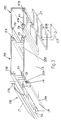
- a top vent 9 is provided for a window 1 (see Fig. 11) which in the conventional way comprises a wooden outer frame 2 supporting the sash 3, the window 1 being set into a wall structure between side walls, head lintels and bottom sill.
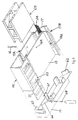
- the vent 9 constitutes a separate independent unit which is secured to the head 10 of the window, especially after completion of the window but before the window is offered up to the wall aperture and comprises three parts, namely a main conduit part 11A and a nose 11B and an outlet (or control) part 11C on respective sides of the main conduit part 11A.
- the main conduit 11A comprises a general box form construction with open ends and a plain interior, the sides 24A, 22A of the conduit 11A defining an air inlet and an air outlet respectively carrying a series of apertures 50A, 50B for lateral airflow through the conduit 11A.
- the nose 11B and the control sections 11C are joined to the main conduit 11A, by male-female interconnections 51 52, 53, 54 and these interconnections are adapted for snap-fitting.
- the nose 11B comprises a downwardly angled canopy portion 17 and a downwardly directed flange or nose/drip 18 joined to the portion 17 by a horizontal apertured wall 56, the flange 18 including an inwardly turned lip 18A.
- the control section 11C shown in Fig. 1 is of channel form and has an apertured bottom wall 22 with opposed groove 57A, 57B adjacent the wall 22 wherein an apertured control plate 21 is slidable.
- the wall 22 and plate 21 define control means for airflow through the vent 9 operating on a hit-or-miss basis depending on whether or not the apertures of the wall 22 and the plate 21 are in alignment. Movement of the plate 21 is facilitated by gripper elements 23 which have a base 23A generally complementary to an aperture of the plate 21 so that the element 23 can be press fitted into the plate 21.
- the nose 11B and the control section 11C are open ended.
- the interconnection 51 comprises a tongue 51A and slot 51B joint whereas the other three interconnections 52-54 are of the bead 58 in groove 59 type.
- the conduit 11A, nose 11B and section 11C defining a unit are made from suitable metal or plastics material and can be cut in suitable lengths from a continuous length mouldings or extrusions, this latter feature considerably facilitating the use of the vent 9 in a wide variety of different sized windows. Longitudinal grooves in the nose 11A serve to receive a gauze (fly) screen 24.
- the open ends of the combined unit 11A-11C are closed by left and right handed end closure caps 15 the right hand one of which is shown in Figs. 4 and 5.
- the cap 15 comprises a recessed base part 60 carrying a set of lugs or tongues 61 engaging with the interior corners of the main conduit 11A, a tongue 62 to locate the canopy portion 17 of nose 11A and a channel form lug 63 locating the control section 11C.
- the base part 60 presents a laterally directed tab plate 64 on which an end of the air control plate 21 is slidable, the tab plate 64 serving to close off a respective end portion of the air flow control 21/22 so that effective air flow control is always possible from zero to maximum rates irrespective of the cut length of the unit 11A-11C.
- a stopper block 65 is housed in the base 60 of one side end cap only to set the movement of the control plate 21.
- a downstand bracket 66 is carried by the plate 64, a hole 67 being present in the bracket 66 for the through-passage of a supplementary control cord 68 fitted to a respective element 23 as shown in Fig. 11; as will be appreciated the control cord 68 will considerably facilitate the operation of the air control 21/22 from a lower level.
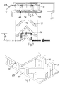
- a removable sound insulating baffle unit or cartridge 69 (Figs. 6 to 8) is housed in the main conduit 11A and comprises a base part 70 having thereon upstanding chevron form walls 71, and a top block 72 mounted on the walls 71 whereby enclosed undulating air passages 73 are present in the unit 69, the wall 71 causing deflection of sound waves in a plane parallel to the base part 70 as shown by the arrows in Fig. 7. Air can pass from the apertures 50 through the air passages 73 to the apertures 51. As can be seen in Fig.
- the unit 69 will contribute to the strength and rigidity of the main conduit 11A and will be made from suitable lightweight insulating material.
- the base 70 and top block 72 can be formed by cutting suitable sized portions from continuous lengths of shaped materials.
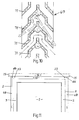
- the walls 71 could of course take a different shape: thus Fig. 10 shows walls 71 of different planar profile (in Fig. 10 the thin line arrows indicate the air flow path while the wider arrows show sound wave deflection).
- an additional sound insulating unit 69A could be located in the control section 11C.
- the air flow control 22/23 is arranged horizontally, while in the modified vent of Fig. 2 the control 22/23 is arranged vertically: it will be noted however that the horizontal control 22/23 of Fig. 1 provides a maximum discharge area which is greater than that of the vertical control of Fig. 2. It is of course possible for the control 22/23 to have some other shape than that shown, for example, quarter round, and the control could discharge the ventilating air in some further alternative direction.
- vent 9 Prior to fitting on the window frame 1, the vent 9 is fully assembled, complete with end caps 15 and the sound insulating cartridge unit or units, if required, the nose 11B having been fitted to conduit 11A by firstly placing the tongue 51A in the slot 51B then snapping the bead 58 into the groove 59 control section 11C is fitted by a straight snap fit of the interconnections 53, 54.
- vent 1 is then placed on the window head 10 and pushed inwards (ie rightwards in Fig 1) to compress the seal 14 against the outer wall 10A of the head 10 and inward movement is arrested by the lip 18A engaging the wall 10A - the outer edge of the lip 18A is set back from the free surface of the seal 14 (see Fig 2) by a predetermined amount to control the achievable compression on seal 14 and also to prevent capillarity attraction of moisture - and in this compressed position the vent 9 is secured to the head 10 by means of screws 16 (Fig 9) passing through screwholes 16A in the conduit 11A.
- the window 1 with vent 9 in place is now offered up to the window aperture in the building wall and the window surround construction completed so that the vent 9 is located between the building head lintel and the window frame head 10.
- the above vent 9 of the present invention has the following advantages:-
- the window vent of Fig. 12 is closely similar to the vent of Fig. 1 and like parts carry like reference numerals.
- the main conduit 11A is made initially in open form (eg by extrusion ie as an open channel base 13A) and is closed, when the parts 11A, 11B, 11C of the vent are assembled, by virtue of a top wall 33 of the tail section 11C extending over the open channel base, the wall 33 including an additional bead 53A for snap fitting in male/female fashion at the front end of conduit 11A. Therefore the bulk of the parts of vent 9 can be of open channel form and none need be of closed-box form: this considerably conveniences the manufacture of the parts especially where an extrusion process is involved.
- a sealing strip 34 of hollow cylindrical section is used (the non compressed strip state is shown dashed) differing from the previous strip section, and the strip 34 has a T-head received in a complementary slot in the flange 18.
Landscapes
- Engineering & Computer Science (AREA)
- Civil Engineering (AREA)
- Structural Engineering (AREA)
- Specific Sealing Or Ventilating Devices For Doors And Windows (AREA)
- Transition And Organic Metals Composition Catalysts For Addition Polymerization (AREA)
- External Artificial Organs (AREA)
- Extrusion Moulding Of Plastics Or The Like (AREA)
- Compressor (AREA)
- Respiratory Apparatuses And Protective Means (AREA)
Claims (15)
- Structure de ventilation destinée à être adaptée à une fenêtre pour former un ensemble de fenêtre ventilé (1) destiné à être installé dans l'emplacement d'une fenêtre dans un mur, ce volume de ventilation (9) comprenant un conduit aplati (11A-11C) adapté sous forme d'une unité séparée et indépendante à un rebord extérieur (10B) d'un châssis de fenêtre (10) de manière telle que quand l'ensemble de fenêtre ( 1) comportant la volume de ventilation (9) est logé dans l'ouverture d'une fenêtre, le volume de ventilation (9) est situé entre le châssis (10) et le mur comportant l'ouverture pour une fenêtre, ledit conduit (11A-11C) se composant d'un corps de conduit principal (11A) destiné à être placé par dessus ledit rebord extérieur (10B) du châssis (10) et d'ailes latérales (18) à une extrémité extérieure dudit corps de conduit principal (11A) comportant des moyens d'isolation (14) destinés à rencontrer une surface latérale verticale (10A) et des moyens de contrôle d'écoulement de l'air (22A) comprenant une première plaque d'ouverture (21) mobile par rapport à une seconde plaque d'ouverture fixe (22), de manière telle que ces moyens de contrôle constituent une commande empirique,
caractérisée en ce que, dans le but de permettre à l'ensemble de fenêtre ventilée d'être mis en position par rapport au mur, lesdites ailes (18) à l'extrémité extérieure du corps de conduit ne dépassent que vers l'intérieur, de manière à n'assurer l'isolation qu'avec une surface latérale (10A) du châssis (10) par l'intermédiaire des moyens d'isolation (14), en ce que lesdits moyens de contrôle d'écoulement d'air (22A) sont inclus dans la portion extérieure (11C) du conduit (11A-11C), et en ce que des chapeaux terminaux adaptables (15) sont prévus pour obturer les extrémités du conduit (11A-11C) et se composent de prolongements (61, 62, 63) qui sont reçus dans des douilles prévues dans le conduit (11A-11C), l'un de ces chapeaux (15) comportant une butée (65) contre laquelle bute une première extrémité de la première plaque (21) des moyens de contrôle (22A) quand les premières extrémités des plaques de contrôle (21, 22) sont alignées dans une position terminale des moyens de contrôle (22A) tandis que l'autre chapeau (15) constitue un logement destiné à recevoir la seconde extrémité de ladite première plaque (21) pour le déplacement de la première plaque (21) vers l'autre position terminale des moyens de contrôle. - Structure de ventilation selon la revendication 1, caractérisée en ce que lesdits chapeaux terminaux (15) comportant au surplus un élément créant une surface latérale (64) servant a chevaucher lesdites plaques ajourées (22, 24) de manière à ce que le contrôle d'écoulement d'air (22A) puisse être complètement fermé quelle que soit la longueur choisie pour le conduit (11A-C).
- Structure de ventilation selon la revendication 2, caractérisée en ce qu'on prévoit un mécanisme de contrôle à distance sous forme d'un cordon de contrôle (68) pour le contrôle d'écoulement d'air (22A), ce mécanisme comprenant dos moyens de contrôle (23) du déplacement de la plaque d'ouverture (21), des cordons (68) étant fixés à ces moyens (23), et des moyens de guidage (66) sur les chapeaux terminaux (15) pour guider ces cordons (68).
- Structure de ventilation selon la revendication 3, caractérisée en ce que les moyens de guidage (66) sont situés sur les surfaces latérales (64) des chapeaux terminaux (15).
- Structure de ventilation selon l'une quelconque des revendications précédentes, comprenant un ensemble de ventilations se composant d'un nez (11B) et de portions de sorties (11C) sur chaque côté du corps de conduit principal (11A), au moins l'un d'entre eux étant sous forme d'une unité interchangeable séparée, des moyens de jonction (51-54) étant prévus pour réunir cette unité interchangeable au corps du conduit principal (11A), caractérisée en ce qu'un décrochement est prévu entre une portion supérieure du nez (11B) et l'extrémité extérieure du corps de conduit principal (11A), ce décrochement étant situé au-dessous de la surface supérieure du corps de conduit principal (11A).
- Structure de ventilation selon l'une quelconque des revendications précédentes, caractérisée en ce qu'une portion de sortie (11C) du conduit est agencée de manière à surplomber l'élément de chassis supporté (10A), et une évacuation d'air dirigée vers le bas (22A) est prévue dans cette portion de sortie (11C).
- Structure de ventilation selon l'une quelconque des revendications précédentes, caractérisée en ce qu'elle est formée d'éléments (13A, 17, 33, figure 12) en forme de canal ouvert mais qui s'adaptent les uns aux autres pour former un élément de conduit creux (11A, 11B, 11C).
- Structure de ventilation selon la revendication 5, caractérisée en ce que les éléments ou portions des conduits (11A-11C) sont réunis ensemble par des moyens de jonction comprenant des accouplements mâle-femelle à fente (51-54).
- Structure de ventilation selon les revendications 5 ou 6, caractérisée en ce que les ailes (18) sont portées par le nez (11B) et ont la forme d'un nez dirigé vers le bas ou d'un égouttoir.
- Structure de ventilation selon l'une quelconque des revendications précédentes caractérisée en ce que le conduit (11A) a une surface inférieure (13) pratiquement plane de manière à pouvoir être placée sur une surface supérieure (10B) d'un élément de châssis (10).
- Structure de ventilation selon la revendication 1, caractérisée en ce que l'aile (18) comporte une lèvre (18A) tournée vers l'intérieur.
- Structure de ventilation selon l'une quelconque des revendications précédentes, caractérisée en ce que le moyen d'isolation (14) est à section rectangulaire et est réalisé par exemple en une matière plastique synthétique telle que le Néoprène fixée à l'aile (18).
- Structure de ventilation selon l'une quelconque des revendications précédentes, caractérisée en ce que le moyen d'isolation (34, figure 12) comporte une base profilée insérée dans un logement de forme complémentaire de l'aile (18).
- Structure de ventilation selon la revendication 13, caractérisée en ce que le moyen d'isolation (34) présente une tête élastique en forme de profilé à section circulaire rencontrant de façon étanche la surface latérale verticale (10A) de l'élément de châssis.
- Structure de ventilation selon l'une quelconque des revendications précédentes, caractérisée en ce qu'un élément formant chicane isolante phonique (69) est logée dans le corps de conduit principal (11A).
Applications Claiming Priority (5)
| Application Number | Priority Date | Filing Date | Title |
|---|---|---|---|
| GB8715570 | 1987-07-02 | ||
| GB878715570A GB8715570D0 (en) | 1987-07-02 | 1987-07-02 | Vent for windows |
| GB8729328 | 1987-12-16 | ||
| GB878729328A GB8729328D0 (en) | 1987-12-16 | 1987-12-16 | Improved window vent |
| PCT/GB1988/000524 WO1989000233A1 (fr) | 1987-07-02 | 1988-07-04 | Aeration amelioree pour fenetres et ouvertures analogues |
Publications (2)
| Publication Number | Publication Date |
|---|---|
| EP0324820A1 EP0324820A1 (fr) | 1989-07-26 |
| EP0324820B1 true EP0324820B1 (fr) | 1995-04-19 |
Family
ID=26292432
Family Applications (1)
| Application Number | Title | Priority Date | Filing Date |
|---|---|---|---|
| EP88905944A Expired - Lifetime EP0324820B1 (fr) | 1987-07-02 | 1988-07-04 | Aeration amelioree pour fenetres et ouvertures analogues |
Country Status (5)
| Country | Link |
|---|---|
| EP (1) | EP0324820B1 (fr) |
| AT (1) | ATE121492T1 (fr) |
| DE (1) | DE3853626D1 (fr) |
| NO (1) | NO890881L (fr) |
| WO (1) | WO1989000233A1 (fr) |
Cited By (3)
| Publication number | Priority date | Publication date | Assignee | Title |
|---|---|---|---|---|
| GB2527065A (en) * | 2014-06-10 | 2015-12-16 | Hl Plastics Ltd | Improvements in or relating to door and window assemblies |
| SE541181C2 (sv) * | 2014-09-15 | 2019-04-23 | Casamja Ab | Ljuddämpningsanordning för genomgående öppning i fönsterkarm eller annan skiljeyta |
| GB2628832A (en) * | 2023-04-06 | 2024-10-09 | Window Widgets Ltd | Trickle vent cover |
Families Citing this family (7)
| Publication number | Priority date | Publication date | Assignee | Title |
|---|---|---|---|---|
| GB8906224D0 (en) * | 1989-03-17 | 1989-05-04 | Hamilton John G | Fastening device for ventilation ducts |
| GB2296320B (en) * | 1994-12-20 | 1999-02-24 | Abbott Joinery Ltd | Window System |
| GB2311127A (en) * | 1996-03-14 | 1997-09-17 | Heywood Williams Plastics Limited | Ventilation adjacent to window or door assemblies |
| GB9807178D0 (en) * | 1998-04-04 | 1998-06-03 | Hardie John | Ventilator for use with door/window frame |
| GB9821933D0 (en) * | 1998-10-09 | 1998-12-02 | Top Frame Ltd | Ventilator |
| NL1010535C2 (nl) * | 1998-11-12 | 1999-11-24 | Lans Holding B V J | Kozijnregel uit extrusieprofieldelen alsmede samenstel van een dergelijk kozijnregel en daarachter geplaatste suskast en werkwijze voor het vormen van een kozijnregel. |
| GB2623097A (en) * | 2022-10-05 | 2024-04-10 | Liniar Ltd | Improvements in or relating to window assemblies |
Family Cites Families (7)
| Publication number | Priority date | Publication date | Assignee | Title |
|---|---|---|---|---|
| GB897350A (en) * | 1959-12-10 | 1962-05-23 | A V R Achat Ventes Representat | Improvements in or relating to a metal partition-wall, curtain wall, or like wall construction |
| DE2360002C2 (de) * | 1973-12-01 | 1985-08-29 | Dieter 7340 Geislingen Rau | Rolladenkasten |
| DE2918409A1 (de) * | 1979-05-08 | 1980-11-13 | Hering Ute | Blendrahmen |
| DE2919682A1 (de) * | 1979-05-16 | 1980-11-20 | Siegenia Frank Kg | Lueftungsvorrichtung fuer den einbau in fenster und/oder in andere wandoeffnungen von gebaeuden |
| GB2092652B (en) * | 1981-02-10 | 1985-02-06 | Dixon International Ltd | Draught excluder weather seal and/or smike seal |
| DE8206788U1 (de) * | 1982-03-11 | 1982-08-05 | Siegenia-Frank Kg, 5900 Siegen | Lueftungsvorrichtung fuer den einbau in fenster und/oder in andere wandoeffnungen von gebaeuden |
| DE3422151A1 (de) * | 1984-06-14 | 1986-01-02 | Gebrüder Kömmerling Kunststoffwerke GmbH, 6780 Pirmasens | Schallschutzfenster |
-
1988
- 1988-07-04 WO PCT/GB1988/000524 patent/WO1989000233A1/fr not_active Ceased
- 1988-07-04 DE DE3853626T patent/DE3853626D1/de not_active Expired - Lifetime
- 1988-07-04 AT AT88905944T patent/ATE121492T1/de not_active IP Right Cessation
- 1988-07-04 EP EP88905944A patent/EP0324820B1/fr not_active Expired - Lifetime
-
1989
- 1989-03-01 NO NO89890881A patent/NO890881L/no unknown
Cited By (3)
| Publication number | Priority date | Publication date | Assignee | Title |
|---|---|---|---|---|
| GB2527065A (en) * | 2014-06-10 | 2015-12-16 | Hl Plastics Ltd | Improvements in or relating to door and window assemblies |
| SE541181C2 (sv) * | 2014-09-15 | 2019-04-23 | Casamja Ab | Ljuddämpningsanordning för genomgående öppning i fönsterkarm eller annan skiljeyta |
| GB2628832A (en) * | 2023-04-06 | 2024-10-09 | Window Widgets Ltd | Trickle vent cover |
Also Published As
| Publication number | Publication date |
|---|---|
| NO890881D0 (no) | 1989-03-01 |
| NO890881L (no) | 1989-04-26 |
| DE3853626D1 (de) | 1995-05-24 |
| ATE121492T1 (de) | 1995-05-15 |
| WO1989000233A1 (fr) | 1989-01-12 |
| EP0324820A1 (fr) | 1989-07-26 |
Similar Documents
| Publication | Publication Date | Title |
|---|---|---|
| CA1115133A (fr) | Chassis combine a porte et fenetre | |
| US4351137A (en) | Plastic panel mounting frame | |
| US5365707A (en) | Architectural element for attaching to a structure | |
| EP0612369B1 (fr) | Dispositif de ventilation | |
| EP0324820A1 (fr) | Aeration amelioree pour fenetres et ouvertures analogues | |
| GB2194038A (en) | Window vent | |
| US5283995A (en) | Door light frame assembly | |
| EP0719373A1 (fr) | Ensemble joint d'angle | |
| GB2116694A (en) | Ventilators | |
| US4019429A (en) | Ventilator | |
| GB2131072A (en) | Window frame construction with water drain | |
| US4027581A (en) | Ventilator | |
| GB2250530A (en) | Fixing frames for windows, doors and the like | |
| EP0285644B1 (fr) | Dispositif de ventilation | |
| US5746654A (en) | Ventilator | |
| JP3340909B2 (ja) | 窓枠用換気装置 | |
| GB2126333A (en) | Ventilators | |
| JPH0423186Y2 (fr) | ||
| JP3211059B2 (ja) | 合成樹脂製の窓枠 | |
| JP2846828B2 (ja) | アルミサッシ用換気装置 | |
| GB2345533A (en) | Glazing assemblies and ventilators in frame or sash of window or door | |
| US2168922A (en) | Window assembly | |
| KR950006409B1 (ko) | 환기 가능한 슬라이딩 밀폐 어셈블리 | |
| KR102205522B1 (ko) | 미닫이형 자동문 | |
| GB2301664A (en) | A ventilator |
Legal Events
| Date | Code | Title | Description |
|---|---|---|---|
| PUAI | Public reference made under article 153(3) epc to a published international application that has entered the european phase |
Free format text: ORIGINAL CODE: 0009012 |
|
| AK | Designated contracting states |
Kind code of ref document: A1 Designated state(s): AT BE CH DE FR GB IT LI LU NL SE |
|
| 17P | Request for examination filed |
Effective date: 19890712 |
|
| 17Q | First examination report despatched |
Effective date: 19900221 |
|
| RAP3 | Party data changed (applicant data changed or rights of an application transferred) |
Owner name: HAMILTON, JOHN GEORGE |
|
| RAP1 | Party data changed (applicant data changed or rights of an application transferred) |
Owner name: PRODUCT DESIGN & INNOVATION LIMITED |
|
| GRAA | (expected) grant |
Free format text: ORIGINAL CODE: 0009210 |
|
| AK | Designated contracting states |
Kind code of ref document: B1 Designated state(s): AT BE CH DE FR GB IT LI LU NL SE |
|
| PG25 | Lapsed in a contracting state [announced via postgrant information from national office to epo] |
Ref country code: IT Free format text: LAPSE BECAUSE OF FAILURE TO SUBMIT A TRANSLATION OF THE DESCRIPTION OR TO PAY THE FEE WITHIN THE PRESCRIBED TIME-LIMIT;WARNING: LAPSES OF ITALIAN PATENTS WITH EFFECTIVE DATE BEFORE 2007 MAY HAVE OCCURRED AT ANY TIME BEFORE 2007. THE CORRECT EFFECTIVE DATE MAY BE DIFFERENT FROM THE ONE RECORDED. Effective date: 19950419 Ref country code: BE Effective date: 19950419 Ref country code: AT Effective date: 19950419 Ref country code: NL Free format text: LAPSE BECAUSE OF FAILURE TO SUBMIT A TRANSLATION OF THE DESCRIPTION OR TO PAY THE FEE WITHIN THE PRESCRIBED TIME-LIMIT Effective date: 19950419 Ref country code: CH Effective date: 19950419 Ref country code: LI Effective date: 19950419 Ref country code: FR Effective date: 19950419 |
|
| REF | Corresponds to: |
Ref document number: 121492 Country of ref document: AT Date of ref document: 19950515 Kind code of ref document: T |
|
| REF | Corresponds to: |
Ref document number: 3853626 Country of ref document: DE Date of ref document: 19950524 |
|
| PG25 | Lapsed in a contracting state [announced via postgrant information from national office to epo] |
Ref country code: SE Effective date: 19950719 |
|
| PG25 | Lapsed in a contracting state [announced via postgrant information from national office to epo] |
Ref country code: DE Effective date: 19950720 |
|
| PG25 | Lapsed in a contracting state [announced via postgrant information from national office to epo] |
Ref country code: LU Free format text: LAPSE BECAUSE OF NON-PAYMENT OF DUE FEES Effective date: 19950731 |
|
| REG | Reference to a national code |
Ref country code: CH Ref legal event code: PL |
|
| EN | Fr: translation not filed | ||
| NLV1 | Nl: lapsed or annulled due to failure to fulfill the requirements of art. 29p and 29m of the patents act | ||
| PLBE | No opposition filed within time limit |
Free format text: ORIGINAL CODE: 0009261 |
|
| STAA | Information on the status of an ep patent application or granted ep patent |
Free format text: STATUS: NO OPPOSITION FILED WITHIN TIME LIMIT |
|
| 26N | No opposition filed | ||
| PGFP | Annual fee paid to national office [announced via postgrant information from national office to epo] |
Ref country code: GB Payment date: 19960702 Year of fee payment: 9 |
|
| PG25 | Lapsed in a contracting state [announced via postgrant information from national office to epo] |
Ref country code: GB Free format text: LAPSE BECAUSE OF NON-PAYMENT OF DUE FEES Effective date: 19970704 |
|
| GBPC | Gb: european patent ceased through non-payment of renewal fee |
Effective date: 19970704 |