EP0324863A1 - Lampe halogène - Google Patents
Lampe halogène Download PDFInfo
- Publication number
- EP0324863A1 EP0324863A1 EP88100355A EP88100355A EP0324863A1 EP 0324863 A1 EP0324863 A1 EP 0324863A1 EP 88100355 A EP88100355 A EP 88100355A EP 88100355 A EP88100355 A EP 88100355A EP 0324863 A1 EP0324863 A1 EP 0324863A1
- Authority
- EP
- European Patent Office
- Prior art keywords
- burner
- housing part
- light
- halogen lamp
- housing
- Prior art date
- Legal status (The legal status is an assumption and is not a legal conclusion. Google has not performed a legal analysis and makes no representation as to the accuracy of the status listed.)
- Withdrawn
Links
Images



Classifications
-
- F—MECHANICAL ENGINEERING; LIGHTING; HEATING; WEAPONS; BLASTING
- F21—LIGHTING
- F21V—FUNCTIONAL FEATURES OR DETAILS OF LIGHTING DEVICES OR SYSTEMS THEREOF; STRUCTURAL COMBINATIONS OF LIGHTING DEVICES WITH OTHER ARTICLES, NOT OTHERWISE PROVIDED FOR
- F21V15/00—Protecting lighting devices from damage
- F21V15/01—Housings, e.g. material or assembling of housing parts
-
- F—MECHANICAL ENGINEERING; LIGHTING; HEATING; WEAPONS; BLASTING
- F21—LIGHTING
- F21V—FUNCTIONAL FEATURES OR DETAILS OF LIGHTING DEVICES OR SYSTEMS THEREOF; STRUCTURAL COMBINATIONS OF LIGHTING DEVICES WITH OTHER ARTICLES, NOT OTHERWISE PROVIDED FOR
- F21V14/00—Controlling the distribution of the light emitted by adjustment of elements
- F21V14/02—Controlling the distribution of the light emitted by adjustment of elements by movement of light sources
-
- F—MECHANICAL ENGINEERING; LIGHTING; HEATING; WEAPONS; BLASTING
- F21—LIGHTING
- F21W—INDEXING SCHEME ASSOCIATED WITH SUBCLASSES F21K, F21L, F21S and F21V, RELATING TO USES OR APPLICATIONS OF LIGHTING DEVICES OR SYSTEMS
- F21W2131/00—Use or application of lighting devices or systems not provided for in codes F21W2102/00-F21W2121/00
- F21W2131/40—Lighting for industrial, commercial, recreational or military use
- F21W2131/406—Lighting for industrial, commercial, recreational or military use for theatres, stages or film studios
Definitions
- the invention relates to a halogen lamp with a housing, at least one burner reflector unit within the housing and a light exit opening in the housing for the burner reflector unit.
- Halogen lights of this type are common. However, they only have a single light exit opening which is rigidly assigned to the burner reflector unit. The light emitted by the halogen lamp is therefore unchangeable and is determined by the burner reflector unit and the properties of the light exit opening. For example, a colored filter could be provided in the light exit opening.
- the halogen lamp is designed for the emission of hard light, then if the emission of soft light is desired, the halogen lamp must be replaced. This is particularly uncomfortable for film and video recordings, as two or more halogen lights must be carried or kept ready.
- the housing has at least two light outlet openings, which are equipped differently for different light emission, and that the light outlet openings are rotatable relative to the burner reflector unit, so that either one of the light outlet openings can interact with the burner reflector unit.
- the desired light exit opening can interact with the burner reflector unit. It is therefore not necessary to carry several different halogen lights with you if you want to be able to change the light. This fact is of interest not only for film or video lights, but also in general for use lights in the living area. Here, too, a hard light may sometimes be desired, and a soft light, or a change in the color of the light, etc., may be desired.
- the housing preferably has a lower housing part to which the burner reflector unit is fastened, and an upper housing part which has the light exit openings and can be rotated relative to the lower housing part.
- the lower part of the housing will generally have the shape of a plate, while the upper part of the housing will be cup-shaped and surround the burner-reflector unit from above, the light outlet openings being provided in the side wall of the upper part of the cup-shaped housing.
- the stand is on the lower part of the housing foot of the lamp or other holding device can be fastened, and it goes without saying that the terms lower housing part and upper housing part should not be understood restrictively in the sense that the housing part is actually always below the upper housing part, because it is of course also an assembly of the lamp possible that the lower housing part is above the upper housing part.
- the outline of the housing is expediently square in the plane perpendicular to the axis of rotation. A light exit opening can then be provided on each side of the square.
- the outline of the housing could just as well be an isosceles triangle. Then, however, the possibility of light variation would be correspondingly reduced in accordance with the smaller number of side walls of the upper housing part.
- three differently equipped light outlet openings are provided on the sides of the square, wherein on the side of the housing that does not have a light outlet opening, different film filters can be stored, which can optionally be in at least one light outlet opening adjacent to this side are slidable.
- the film filters can easily be pushed around the 90 ° corner between their storage space and the light exit opening, as they are known to be flexible.
- An embodiment of the invention is considered to be particularly advantageous, in which at least two burner reflector units are combined to form a light source unit, which are compared to any predetermined one Light exit opening are rotatable so that either one of the burner reflector units interacts with the predetermined light exit opening.
- the burner horizontally in one of the burner reflector units and to arrange the burner vertically in another of the burner reflector units.
- the burner lies on the axis of a rotating body that forms the reflector, while in the vertical arrangement of the burner, the latter will lie parallel to an only simply curved surface, for example in the form of a parabola, so that different radiation conditions result that can be connected to each of the light exit openings.
- the variety of light emission options can thus be significantly increased.
- the advantage remains that when a burner is exported, it is possible to quickly switch to a replacement burner, because the burner can be converted from one burner reflector unit into another burner reflector unit at any time through an opening for light opening.
- the light exit openings in halogen lamps for example by means of bulletproof glass, must be secured in such a way that there is no danger to the environment when a burner explodes.
- Is advantageously between the lower housing part and the light source unit has a power supply device which supplies only the burner reflector unit which is in a predetermined position with respect to the lower housing part.
- a ring electrode which is concentric to the axis of rotation is expediently provided on the light source unit and is contacted by a first grinder fixedly connected to the lower housing part, and individual electrodes which are arranged concentrically to the axis of rotation and are assigned to the individual burner reflector units and are provided with a second grinder, firmly connected to the lower part of the housing.
- each burner-reflector unit is assigned a switch button which interacts with a micro switch that is fixedly connected to the lower housing part for power supply to the second wiper only when one of the burner-reflector units is in the predetermined position.
- the micro button prevents the individual electrodes from scorching when the light source unit is rotated in view of the high power consumption of, for example, 100 watts.
- the housing parts and the light source unit each have a bearing that blocks on one side, the bearings blocking in opposite directions.
- a relative rotation of the two housing parts in one direction of rotation causes a change in the light exit openings with the same burner reflector unit, while a change in the burner reflector units takes place through a relative rotation in the other direction of rotation with a constant light exit opening.
- a blocking bearing or different detents are provided between the upper housing part and the lower housing part, while the light source unit is rotatably mounted on the upper housing part and the lower housing part and a ratchet acting on the light source unit is provided with a lever projecting outwards.
- the light exit openings can be selected by rotating in one or in the other direction of the upper housing part relative to the lower housing part or vice versa, while the burner reflector unit is selected by actuating the ratchet.
- a special embodiment of the halogen lamp according to the invention is shown, which due to its versatility is also referred to as a universal lamp.
- the outline of the universal lamp is approximately square (see, for example, FIG. 5) and has a cup-shaped housing upper part 10 and a plate-shaped housing lower part 12.
- light outlet openings In three of the four side walls of the cup-shaped housing upper part 10, light outlet openings (FIGS. 1, 2 and 4) are provided for a light source unit 14 located within the housing with a total of four burner reflector units 16a to 16d which are perpendicular to one another (see, for example, FIG. 7).
- a light exit opening 18 in the upper housing part 10 is round and closed with a clear glass 20 (see FIG. 1). It is generally combined with a burner reflector unit, for example 16b (see FIG. 7), in which the burner 22 extends horizontally in the axis of rotation of a parabolic mirror surface 24. With this combination, the universal light emits a hard, concentrated light.
- the light exit opening 18 'shown in Fig. 4' is square and covered with the help of two rows of staggered glass tubes 26, as shown in particular in Fig. 1.
- These glass tubes 26, which are made of safety glass, are arranged with respect to one another and spaced apart from one another such that in the event of an explosion of the burner, people in the Environment cannot be endangered.
- the arrangement of the glass tubes 26 has the result that the light deflected by reflection and refraction, which passes through the two rows of glass tubes, is softened and emitted within a large solid angle.
- this light exit opening can be provided with light flaps 28, as is the case with a conventional film or video light.
- This light exit opening is generally combined with a burner reflector unit, in which the burner is arranged horizontally and parallel to the glass tubes near the axis of a mirror surface 30 which is simply curved in the form of a parabola, as is the case, for example, with the burner reflector unit 16c in FIG 7 is shown.
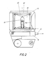
- FIG. 2 shows another square light exit opening 18 ⁇ in the pot-shaped upper housing part 10.
- This light exit opening is also covered by a clear safety glass 20 and generally interacts with a burner reflector unit 16d, in which the burner 22 is arranged vertically in the axis of a mirror surface 32 which is only curved in the form of a parabola (see FIG. 2).
- this combination emits a wide bundle of hard light.
- FIG. 3 shows the side wall of the upper housing part 10, which has no light exit opening and is preferably adjacent to the light exit opening 18 ⁇ (see FIG. 2).
- Parallel to this side wall within the upper housing part 10 are three film filters arranged, which can be pushed with the help of sliders 34 in front of the light outlet opening 18 ⁇ .
- the flexible film filters can easily be deflected by 90 ° at the corner between the two side walls. Different colored light can thus be emitted from the light exit opening 18 ⁇ .
- Fig. 1 it is indicated that the safety glass 32 of the square light outlet opening 18 ⁇ can be opened for a burner change. If a burner is defective, it is not necessary to separate the upper part of the housing from the lower part of the housing. Rather, the defective burner can be quickly replaced by bringing it to the light exit opening 18 ⁇ and then opening the safety glass 32, which is secured in the closed position with the aid of a locking mechanism (not shown), for access to the burner reflector unit in question.
- the sliding path 36 for a film filter is illustrated in the top view in FIG. 5.
- air outlet openings on the top of the upper housing part 10 are designated.
- the reference numeral 40 denotes two extendable rods for attaching accessories.
- 42 is an actuating pin that can be pushed into the housing for unlocking the locking mechanism for the window containing the safety glass 32 at the opening 18 ⁇ (see FIG. 1).
- an articulated foot for the universal lamp is also shown in part, but this is not the subject of the invention and is therefore not described in more detail.
- the pot-shaped upper housing part 10 is rotatably connected to the plate-shaped lower housing part 12 via an axis 46.
- the four burner reflector units 16a to 16d of the light source unit 14, which are oriented perpendicular to one another and the light exit openings in the housing upper part 10, are arranged around the axis 46.
- the two ends of the axis 46 are each connected to the associated housing part via two counteracting needle bearings 48 which block on one side.
- the upper housing part can be rotated relative to the light source unit, while by rotating the upper housing part relative to the lower housing part in the other direction of rotation, the light source unit 14 is rotated relative to the lower housing part.
- different light outlet openings can be assigned to one specific burner reflector unit in one direction of rotation, while different burner reflector units can optionally be assigned to a specific light outlet opening in the other direction of rotation. So every burner-reflector unit can be combined with every light exit opening.
- FIG 8 shows a modified embodiment in which a latching mechanism 48 is provided between the upper housing part 10 and the lower housing part in order to releasably lock the upper housing part in four possible positions relative to the lower housing part, and is a ratchet mechanism 50 for the axle instead of the needle bearing 48 46 is provided, which can be actuated from the outside via a lever 52, so that the light source unit 14 is opposite the
- the lower housing part 12 or the upper housing part 10 can be rotated step by step. The rotation of the upper housing part 10 relative to the lower housing part 12 is rotated after overcoming the locking force of the locking device 48.
- the power supply device for the light source unit 14 is shown in FIGS. 9 and 10.
- a ring electrode 54 is arranged concentrically to the axis of rotation, which is contacted by a first grinder 56 fastened in the upper housing part.
- individual electrodes 58 are provided which are assigned to the individual burner reflector units and which cooperate with a second grinder 60, which is also fastened to the upper housing part 10. This ensures that only that burner-reflector unit is supplied with current whose individual electrode 58 is in contact with the grinder 60.
- a microswitch 60 is also attached to the upper housing part 10 as shown, which interacts with the switching cams 62 assigned to the individual electrodes 58.
- the microswitch 60 switches the current to the grinder 60 only after it has been actuated. In this way, since the individual electrode 58 comes into contact with the sliding contact 60 before the microswitch 60 passes the current, the contacts between the sliding contact 60 and the single electrode 58 are prevented from scorching in the initial contact phase.
- Burners of different capacities can be used. If a burner fails, after the be hitting burner reflector unit to the light exit opening 18 ⁇ shown in Fig. 2 has been rotated, the burner can be removed. An intact burner can be removed from another burner reflector unit, which is also rotated toward the light exit opening 18 ⁇ , and inserted into the burner reflector unit, the burner of which failed. After four burners are available, the universal lamp according to the invention ensures that it is always operational.
Landscapes
- Engineering & Computer Science (AREA)
- General Engineering & Computer Science (AREA)
- Non-Portable Lighting Devices Or Systems Thereof (AREA)
Priority Applications (1)
| Application Number | Priority Date | Filing Date | Title |
|---|---|---|---|
| EP88100355A EP0324863A1 (fr) | 1988-01-13 | 1988-01-13 | Lampe halogène |
Applications Claiming Priority (1)
| Application Number | Priority Date | Filing Date | Title |
|---|---|---|---|
| EP88100355A EP0324863A1 (fr) | 1988-01-13 | 1988-01-13 | Lampe halogène |
Publications (1)
| Publication Number | Publication Date |
|---|---|
| EP0324863A1 true EP0324863A1 (fr) | 1989-07-26 |
Family
ID=8198640
Family Applications (1)
| Application Number | Title | Priority Date | Filing Date |
|---|---|---|---|
| EP88100355A Withdrawn EP0324863A1 (fr) | 1988-01-13 | 1988-01-13 | Lampe halogène |
Country Status (1)
| Country | Link |
|---|---|
| EP (1) | EP0324863A1 (fr) |
Citations (3)
| Publication number | Priority date | Publication date | Assignee | Title |
|---|---|---|---|---|
| FR1110148A (fr) * | 1954-09-04 | 1956-02-06 | Lampe de table | |
| DE1489389B1 (de) * | 1963-05-08 | 1971-12-02 | Berkey Technical U H Ltd | Scheinwerfer fuer fernseh und filmstudios zur wahlweisen verwendung als flutlicht oder als punktlichtscheinwerfer |
| US3959612A (en) * | 1974-09-25 | 1976-05-25 | Designs For Vision, Inc. | Rotary switch assembly particularly adapted for use with fiber optic light sources |
-
1988
- 1988-01-13 EP EP88100355A patent/EP0324863A1/fr not_active Withdrawn
Patent Citations (3)
| Publication number | Priority date | Publication date | Assignee | Title |
|---|---|---|---|---|
| FR1110148A (fr) * | 1954-09-04 | 1956-02-06 | Lampe de table | |
| DE1489389B1 (de) * | 1963-05-08 | 1971-12-02 | Berkey Technical U H Ltd | Scheinwerfer fuer fernseh und filmstudios zur wahlweisen verwendung als flutlicht oder als punktlichtscheinwerfer |
| US3959612A (en) * | 1974-09-25 | 1976-05-25 | Designs For Vision, Inc. | Rotary switch assembly particularly adapted for use with fiber optic light sources |
Similar Documents
| Publication | Publication Date | Title |
|---|---|---|
| DE2133719C3 (de) | Operationsleuchte | |
| DE4021987C2 (fr) | ||
| DE2150087C2 (de) | Beleuchtungsvorrichtung für zahnärztliche | |
| DE1293286B (de) | Beleuchteter Druckknopf-Schaltmechanismus | |
| DE4227468C2 (de) | Elektrische Schaltereinheit, insbesondere zur Steuerung von Klimaanlagen in Kraftfahrzeugen | |
| DE2753545A1 (de) | Kraftfahrzeugscheinwerfer mit polarisiertem und unpolarisiertem lichtanteil | |
| DE2122330B2 (de) | Operationsleuchte | |
| DE2701948A1 (de) | Operationsleuchte | |
| DE3605226A1 (de) | Blendungsfreie leuchte mit streifenfoermigem abblendreflektor | |
| DE1598089B2 (de) | Vorrichtung zur optischen Spektralanalyse | |
| DE3020097C2 (de) | Signalleuchte | |
| DE3781241T2 (de) | Sonnenblende mit spiegelbeleuchtung und schwenkbarer abdeckung. | |
| EP0184695A1 (fr) | Diaphragme pour rayonnement primaire dans un appareil d'examen radiologique | |
| DE3433604A1 (de) | Betaetigungsvorrichtung fuer elektrische schalter | |
| DE2744140A1 (de) | Beleuchtungsvorrichtung fuer aerztliche, insbesondere zahnaerztliche zwecke | |
| DE3500860A1 (de) | Optische anordnung an passiv-infrarot-bewegungsmeldern | |
| DE3401463C2 (de) | Elektronisches Blitzgerät hoher Leitzahl | |
| DE2263803B2 (de) | Plattenfoermiges raster fuer beleuchtungsarmatur | |
| EP0560216B1 (fr) | Réglage au foyer d'une source lumineuse dans un boîtier d'éclairage | |
| DE1566123C2 (de) | Röntgengerät mit zurückspringendem Fenster und nahe dem Fenster angeordneten VerschluBelementen | |
| EP0398275A2 (fr) | Pare-soleil pour véhicules automobiles | |
| DE2512763A1 (de) | Leuchte, insbesondere filmleuchte | |
| AT363354B (de) | Lichtsignal | |
| DE4411890A1 (de) | Leuchte | |
| DE6608851U (de) | Abschirmvorrichtung fuer den monochromatorkristall einer neutronen-beugungseinrichtung. |
Legal Events
| Date | Code | Title | Description |
|---|---|---|---|
| PUAI | Public reference made under article 153(3) epc to a published international application that has entered the european phase |
Free format text: ORIGINAL CODE: 0009012 |
|
| AK | Designated contracting states |
Kind code of ref document: A1 Designated state(s): AT BE CH DE ES FR GB GR IT LI LU NL SE |
|
| RBV | Designated contracting states (corrected) |
Designated state(s): AT DE ES FR GB IT NL |
|
| STAA | Information on the status of an ep patent application or granted ep patent |
Free format text: STATUS: THE APPLICATION IS DEEMED TO BE WITHDRAWN |
|
| 18D | Application deemed to be withdrawn |
Effective date: 19900129 |