EP0324877A1 - Procédé permettant le changement de rapports d'une transmission automatique d'une automobile en fonction de la température de l'eau de refroidissement - Google Patents
Procédé permettant le changement de rapports d'une transmission automatique d'une automobile en fonction de la température de l'eau de refroidissement Download PDFInfo
- Publication number
- EP0324877A1 EP0324877A1 EP88100808A EP88100808A EP0324877A1 EP 0324877 A1 EP0324877 A1 EP 0324877A1 EP 88100808 A EP88100808 A EP 88100808A EP 88100808 A EP88100808 A EP 88100808A EP 0324877 A1 EP0324877 A1 EP 0324877A1
- Authority
- EP
- European Patent Office
- Prior art keywords
- signal
- cooling water
- water temperature
- control unit
- motor vehicle
- Prior art date
- Legal status (The legal status is an assumption and is not a legal conclusion. Google has not performed a legal analysis and makes no representation as to the accuracy of the status listed.)
- Withdrawn
Links
- 239000000498 cooling water Substances 0.000 title claims abstract description 25
- 238000000034 method Methods 0.000 title claims abstract description 10
- 230000005540 biological transmission Effects 0.000 title abstract description 6
- 230000001133 acceleration Effects 0.000 description 2
- 230000002028 premature Effects 0.000 description 2
- 230000000903 blocking effect Effects 0.000 description 1
- 238000001816 cooling Methods 0.000 description 1
- 230000000881 depressing effect Effects 0.000 description 1
- 238000013021 overheating Methods 0.000 description 1
- 230000001105 regulatory effect Effects 0.000 description 1
Images

Classifications
-
- F—MECHANICAL ENGINEERING; LIGHTING; HEATING; WEAPONS; BLASTING
- F16—ENGINEERING ELEMENTS AND UNITS; GENERAL MEASURES FOR PRODUCING AND MAINTAINING EFFECTIVE FUNCTIONING OF MACHINES OR INSTALLATIONS; THERMAL INSULATION IN GENERAL
- F16H—GEARING
- F16H61/00—Control functions within control units of change-speed- or reversing-gearings for conveying rotary motion ; Control of exclusively fluid gearing, friction gearing, gearings with endless flexible members or other particular types of gearing
- F16H61/16—Inhibiting or initiating shift during unfavourable conditions , e.g. preventing forward-reverse shift at high vehicle speed, preventing engine overspeed
-
- F—MECHANICAL ENGINEERING; LIGHTING; HEATING; WEAPONS; BLASTING
- F16—ENGINEERING ELEMENTS AND UNITS; GENERAL MEASURES FOR PRODUCING AND MAINTAINING EFFECTIVE FUNCTIONING OF MACHINES OR INSTALLATIONS; THERMAL INSULATION IN GENERAL
- F16H—GEARING
- F16H59/00—Control inputs to control units of change-speed- or reversing-gearings for conveying rotary motion
- F16H59/74—Inputs being a function of engine parameters
- F16H59/78—Temperature
Definitions
- the invention relates to a method with which the starting and the acceleration of a motor vehicle can be limited automatically as long as the engine is not heated to the operating temperature.
- An object of the invention is to automatically prevent the load on the non-warmed engine in motor vehicles equipped with an automatic change gearbox, regardless of the will of the vehicle driver.
- the solution according to the invention is based on the knowledge that it is much easier to intervene in the control of the automatic change-speed gearbox than in the implementing system, especially if the control is constructed from electronic elements.
- the invention is thus a method and a control circuit for automatically granting the switching of the forward, reverse, or higher gear stage of an electronically controlled, hydromechanical automatic change gearbox of a motor vehicle as a function of the cooling water temperature, when the temperature required to start the motor vehicle is reached the cooling water of the engine is given a signal at the input of the control unit by means of a heat-sensing signal transmitter and, on the basis of this signal, an enable signal is sent via the output of the control unit to the electrical fittings of the electrohydraulic valve system of the automatic change-speed transmission which switch the 1st, 2nd or reverse gear stage , then when the cooling water temperature required for the higher gear steps is reached, a new signal is given to the input of the control unit and, based on this signal, a new release via the output of the control unit signal to the valves of the electrohydraulic valve system of the automatic change gearbox that switch the higher gear stages.
- the method according to the invention was implemented in the drive device of an urban bus.
- a six-cylinder engine 1 shown in FIG. 1 with diesel operation is connected to a cooling radiator 3 and to cooling water pipes 4 and 5. This is the engine's cooling water system 1.
- the engine 1 transfers the drive to the wheels (not shown) via an electrohydraulically controlled hydromechanical automatic change gear 2 and a cardan shaft 14.
- An electrohydraulic valve system 6 performing the step change of the automatic change gear 2 is controlled by an electronic control unit 13 which the vehicle driver uses a gear selector switch 8 (controller) can influence.
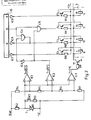
- the elements of the electronic device shown in Figure 2 are installed in the control unit 13, but can also be assembled as an independent unit.
- a temperature signal transmitter 7 is installed in the cooling water pipe 4, which is the return branch of the cooling water system of the engine 1.
- the temperature signal transmitter 7 is a heat degree meter resistor R1 (NTK), which is connected behind the voltage divider R2 to the resistors R4, R5, R6, R7 and to the comparators IC1, IC2, IC3 ( ⁇ A741).
- the electromagnets 9, 10, 11 and 12 of the I., II., III. and the R (reverse) gear stage switching valves of the electro-hydraulic valve system 6 are connected to ground on the one hand via a switch transistor T1 (2 N 3055) and on the other hand via power amplifiers T2, T3, T4 and T5 (BD 240) to the supply voltage.
- the switch transistor T1 is connected to the output of the comparator IC 3 via a resistor R8.
- the stage selector part 15 of the control unit 13 is connected in a manner not shown to the gear selector switch 8 and to the signal transmitters required to determine the appropriate gear stage.
- the signal output of the stage selector part 15 corresponding to the 1st gear stage is connected via a driver stage IC7 (7406) to the power amplifier T2 and, in parallel, via a resistor R9 to the supply voltage.
- the signal output of the stage selector part 15 corresponding to the R (reverse) gear stage is connected to the power amplifier T5 via a driver stage IC9 (7406) and, in parallel, to the supply voltage via a resistor R17.
- the signal output of the stage selector part 15 corresponding to the second gear stage is also connected to the corresponding power amplifier T3 via a driver stage IC8 (7406) and to the supply voltage via a resistor R10, but the output of the NAND gate (7437 ) a power stage IC4 connected to the power amplifier T3.
- One of the inputs of the NAND gate of the power stage IC4 is via a driver stage IC6 (7406) at the output of the comparator IC2, the other input is at III.
- Gear stage corresponding signal output of the stage selector part 15 connected.
- the signal output of the stage selector part 15, which corresponds to the fourth gear stage, is connected to the power amplifier T4 via the one input and output of the NAND gate (7437) of the power stage IC5 and, in parallel, via the resistor R11 to the supply voltage.
- the other input of the NAND gate of power stage IC5 is also connected to the output of the comparator IC2.
- the poles of the heat resistance resistor R1 can be short-circuited by means of a manual switch K1 and a resistor R3.
- the temperature signal transmitter 7 continuously sends the control unit 13 signals about the change in the cooling water temperature.
- the comparators IC2 and IC3 evaluate this signal in such a way that when the cooling water temperature reaches the value of 5 ° C, the signal appears at the output of the comparator IC3 and when it reaches the value of 25 ° C, the signal at the output of the Comparator IC2 appears.
- the temperature values should be selected in such a way that they are approved for the load capacity of the motor.
- the values of 5 ° C and 25 ° C given above are experienced values for a given engine; however, they can generally be used with any engine.
- the switch transistor T1 connects the electromagnets 9, 10, 11, 12 to ground on the basis of the signal from the comparator IC3.
- the power amplifier T2 applies the electromagnet 9 for generating the signal corresponding to the 1st gear stage of the stage selection part 15 to the supply voltage and then after corresponding acceleration of the motor vehicle, the power amplifier T3 applies the electromagnet 10 for generating the signal corresponding to the 2nd gear stage Supply voltage. In this way, the electro-hydraulic valve system 6 has shifted the automatic change gear 2 into the 1st and 2nd gear stages.
- the motor vehicle If the motor vehicle is accelerated further, it reaches the gear for shifting III. Gear required speed.
- the stage selection part 15 generates the signal for switching the III at its corresponding output. Gear. However, this only induces a signal at the output of the NAND gate of the power stage IC5 if a further condition is also fulfilled. Namely, the signal of the output of the comparator IC2 must appear at the input of the NAND gate of the power stage IC5. If this condition is met, the power amplifier T4 connects the electromagnet 11 to the supply voltage on the signal of the output of the NAND gate of the power stage IC5. In this way, the electro-hydraulic valve system 6 switches the automatic change gear 2 into III. Step.
- stage selector switch 8 If the vehicle driver wants to shift into reverse gear, he gives the control unit 13 a corresponding command by means of the gear selector switch 8.
- the signal corresponding to the reverse gear stage from stage selector part 15 connects the electromagnet 12 of the valve of the electro-hydraulic valve system 6 implementing the reverse gear stage via the drive stage IC9 to the supply voltage by means of the power amplifier T5, and if the cooling water temperature is higher than 5 ° C, the switch transistor T1 closes the Electromagnet 12 to the signal of the comparator IC3 also to ground.
- the system can be made independent of the cooling water temperature using the manual switch K1.
- the comparator IC1 ( ⁇ A741) already mentioned is also installed in the system, but this has nothing to do with the method according to the invention.
- the given training offers itself that the overheating of the cooling water can also be observed. Therefore, when the value of 85 ° C. is reached, the comparator IC1 generates a signal with which a warning signal device (signal lamp, acoustic signal), not shown, can be confirmed.
- a warning signal device signal lamp, acoustic signal
Landscapes
- Engineering & Computer Science (AREA)
- General Engineering & Computer Science (AREA)
- Mechanical Engineering (AREA)
- Control Of Transmission Device (AREA)
Applications Claiming Priority (1)
| Application Number | Priority Date | Filing Date | Title |
|---|---|---|---|
| HU862730A HU196927B (en) | 1986-07-01 | 1986-07-01 | Method for stage coupling the automatic gear box of motor vehicle depending on the temperature of cooling water |
Publications (1)
| Publication Number | Publication Date |
|---|---|
| EP0324877A1 true EP0324877A1 (fr) | 1989-07-26 |
Family
ID=10960874
Family Applications (1)
| Application Number | Title | Priority Date | Filing Date |
|---|---|---|---|
| EP88100808A Withdrawn EP0324877A1 (fr) | 1986-07-01 | 1988-01-20 | Procédé permettant le changement de rapports d'une transmission automatique d'une automobile en fonction de la température de l'eau de refroidissement |
Country Status (3)
| Country | Link |
|---|---|
| US (1) | US4894780A (fr) |
| EP (1) | EP0324877A1 (fr) |
| HU (1) | HU196927B (fr) |
Cited By (2)
| Publication number | Priority date | Publication date | Assignee | Title |
|---|---|---|---|---|
| EP0530876A3 (fr) * | 1991-09-06 | 1994-03-09 | Gen Motors Corp | |
| EP3909823A1 (fr) * | 2020-05-12 | 2021-11-17 | RENAULT s.a.s. | Procédé de commande du démarrage d'un véhicule automobile équipé d'une boîte de vitesses automatique et d'un système de post-traitement des gaz d'échappement |
Families Citing this family (17)
| Publication number | Priority date | Publication date | Assignee | Title |
|---|---|---|---|---|
| JPH0297761A (ja) * | 1988-09-30 | 1990-04-10 | Aisin Seiki Co Ltd | 電子制御自動変速装置 |
| JP2948230B2 (ja) * | 1989-02-21 | 1999-09-13 | マツダ株式会社 | 自動変速機を備えた車両のエンジン制御装置 |
| DE3928814A1 (de) * | 1989-08-31 | 1991-03-14 | Porsche Ag | Kraftfahrzeug mit einem selbsttaetig schaltenden getriebe |
| US4986145A (en) * | 1989-11-16 | 1991-01-22 | Chrysler Corporation | Method of engine model determination for use in an electronically-controlled automatic transmission |
| JP2897358B2 (ja) * | 1990-07-11 | 1999-05-31 | 日産自動車株式会社 | 自動変速機の液圧制御装置 |
| US5050451A (en) * | 1990-10-01 | 1991-09-24 | Eaton Corporation | Transmission lubricant temperature/viscosity determination method/apparatus |
| US5275069A (en) * | 1991-03-31 | 1994-01-04 | Mazda Motor Corporation | Control system for automatic transmission |
| US5305663A (en) * | 1992-08-10 | 1994-04-26 | Ford Motor Company | Automatic transmission control system |
| US5803863A (en) * | 1997-03-03 | 1998-09-08 | Caterpillar Inc. | Transmission warm-up control strategy |
| DE19849058A1 (de) * | 1998-10-24 | 2000-04-27 | Zahnradfabrik Friedrichshafen | Verfahren zur Steuerung einer Hochtemperatur-Betriebsart eines elektronisch gesteuerten, automatischen Schaltgetriebes |
| US6227153B1 (en) | 1999-09-17 | 2001-05-08 | General Electric Company | Engine cooling apparatus and method |
| US6394044B1 (en) | 2000-01-31 | 2002-05-28 | General Electric Company | Locomotive engine temperature control |
| US6283100B1 (en) | 2000-04-20 | 2001-09-04 | General Electric Company | Method and system for controlling a compression ignition engine during partial load conditions to reduce exhaust emissions |
| US6286311B1 (en) | 2000-05-16 | 2001-09-11 | General Electric Company | System and method for controlling a locomotive engine during high load conditions at low ambient temperature |
| US6230668B1 (en) | 2000-05-22 | 2001-05-15 | General Electric Company | Locomotive cooling system |
| DE10354930B3 (de) * | 2003-11-25 | 2005-08-04 | Adam Opel Ag | Anfahren eines Kraftfaharzeugs bei ungünstigem Klima |
| US7410446B2 (en) * | 2005-12-19 | 2008-08-12 | Caterpillar Inc. | Oil warming strategy for transmission |
Citations (3)
| Publication number | Priority date | Publication date | Assignee | Title |
|---|---|---|---|---|
| DE3325002A1 (de) * | 1982-07-12 | 1984-01-12 | Honda Giken Kogyo K.K., Tokyo | Steuerverfahren fuer eine vorrichtung zur verhinderung des kriechens bei einem fahrzeug, das mit einem automatischen getriebe ausgeruestet ist |
| US4531432A (en) * | 1982-08-21 | 1985-07-30 | Toyota Jidosha Kabushiki Kaisha | Automatic transmission control device for automobile |
| US4572029A (en) * | 1981-08-26 | 1986-02-25 | Toyota Jidosha Kogyo Kabushiki Kaisha | Speed change control method and device of automatic transmission for vehicle |
Family Cites Families (4)
| Publication number | Priority date | Publication date | Assignee | Title |
|---|---|---|---|---|
| JPS487137B1 (fr) * | 1968-10-30 | 1973-03-03 | ||
| JPS534589B2 (fr) * | 1972-06-26 | 1978-02-18 | ||
| EP0037050A3 (fr) * | 1980-03-27 | 1984-05-09 | Nissan Motor Co., Ltd. | Système de commande du verrouillage pour une transmission automatique à convertisseur de couple verrouillable |
| JPS6049793B2 (ja) * | 1981-03-30 | 1985-11-05 | 日産自動車株式会社 | ロツクアツプ式自動変速機のロツクアツプ制御装置 |
-
1986
- 1986-07-01 HU HU862730A patent/HU196927B/hu not_active IP Right Cessation
-
1988
- 1988-01-20 EP EP88100808A patent/EP0324877A1/fr not_active Withdrawn
- 1988-01-21 US US07/146,516 patent/US4894780A/en not_active Expired - Fee Related
Patent Citations (3)
| Publication number | Priority date | Publication date | Assignee | Title |
|---|---|---|---|---|
| US4572029A (en) * | 1981-08-26 | 1986-02-25 | Toyota Jidosha Kogyo Kabushiki Kaisha | Speed change control method and device of automatic transmission for vehicle |
| DE3325002A1 (de) * | 1982-07-12 | 1984-01-12 | Honda Giken Kogyo K.K., Tokyo | Steuerverfahren fuer eine vorrichtung zur verhinderung des kriechens bei einem fahrzeug, das mit einem automatischen getriebe ausgeruestet ist |
| US4531432A (en) * | 1982-08-21 | 1985-07-30 | Toyota Jidosha Kabushiki Kaisha | Automatic transmission control device for automobile |
Cited By (3)
| Publication number | Priority date | Publication date | Assignee | Title |
|---|---|---|---|---|
| EP0530876A3 (fr) * | 1991-09-06 | 1994-03-09 | Gen Motors Corp | |
| EP3909823A1 (fr) * | 2020-05-12 | 2021-11-17 | RENAULT s.a.s. | Procédé de commande du démarrage d'un véhicule automobile équipé d'une boîte de vitesses automatique et d'un système de post-traitement des gaz d'échappement |
| FR3110128A1 (fr) * | 2020-05-12 | 2021-11-19 | Renault Sas | Procede de commande du demarrage d’un vehicule automobile equipe d’une boite de vitesses automatique et d’un systeme de post-traitement des gaz d’echappement |
Also Published As
| Publication number | Publication date |
|---|---|
| HU196927B (en) | 1989-02-28 |
| HUT45940A (en) | 1988-09-28 |
| US4894780A (en) | 1990-01-16 |
Similar Documents
| Publication | Publication Date | Title |
|---|---|---|
| EP0324877A1 (fr) | Procédé permettant le changement de rapports d'une transmission automatique d'une automobile en fonction de la température de l'eau de refroidissement | |
| DE69612556T2 (de) | Motordrehzahlabbremsung beim hochschalten eines getriebes | |
| DE69929845T2 (de) | Unabhängige Steuerung von Dauerbremsen auf Getriebeseite und Motorseite während des Gangschaltens | |
| DE60212384T2 (de) | Verfahren zur umsteuerung der antriebsrichtung | |
| EP0670789A1 (fr) | Procede permettant de moduler le couple de sortie d'une boite de vitesses automatique | |
| DE102004022929B4 (de) | Störungserfassungsvorrichtung für einen Hydraulikdrucksteuerkreis eines Fahrzeugs | |
| WO1995033631A1 (fr) | Commande de ralentisseur | |
| DE102011008363A1 (de) | Anfahrkupplungsschutz auf einer Neigung bei Fahrzeugstart | |
| DE60008957T2 (de) | Steuerungssystem für die Überbrückungskupplung eines Momentwandlers | |
| DE102011076034A1 (de) | Fahrzeug und Verfahren zum Betreiben eines Fahrzeuges | |
| DE3016620A1 (de) | Antriebsaggregat | |
| WO2001006152A1 (fr) | Dispositif pour commander en fonction de la temperature un embrayage ou une boite de vitesses de vehicule automobile | |
| DE102013003520A1 (de) | Steuerverfahren für ein Doppelkupplungsgetriebe | |
| DE69504148T2 (de) | Kupplungs-steuerungssystem | |
| DE102012001078B4 (de) | Verfahren und hydraulisches steuersystem zum detektieren des vorhandenseins von hydraulikdruck in einem getriebe | |
| DE4392959B4 (de) | Verfahren und Vorrichtung zur Beschleunigung der Erwärmung des Fahrzeugmotors in einem mit einem Retarder ausgestatteten Fahrzeug | |
| EP0324878A1 (fr) | Procédé et installation pour le démarrage prudent et le parcage économique en énergie de véhicules de route à moteur équipés d'une transmission automatique hydromécanique commandée électrohydrauliquement | |
| DE102015109011A1 (de) | Steuervorrichtung für ein Fahrzeug und Steuerverfahren für ein Fahrzeug | |
| DE4446085B4 (de) | Verfahren und Anordnung für retardergesteuerte Beeinflussung der Schaltpunkte in Schaltsystemen für Getriebe von Kraftfahrzeugen | |
| DE10153413A1 (de) | Kick-down-Schaltsteuerverfahren für Fünf-Gang Automatikgetriebe | |
| DE102008024059A1 (de) | Verfahren zur Steuerung eines automatischen Anschaltvorgangs einer automatisch abgeschalteten Antriebseinheit | |
| AT503595B1 (de) | Als montageeinheit ausgebildete kupplungsbetätigung | |
| DE3632960A1 (de) | Steuervorrichtung fuer ein zum antrieb eines kraftfahrzeuges verwendetes antriebsaggregat mit einem antriebsmotor und einem automatischen wechselgetriebe | |
| DE102005021924B4 (de) | Verfahren zur Steuerung einer Standabkopplungsfunktion für ein Automatgetriebe eines Kraftfahrzeugs sowie ein Automatgetriebe | |
| DE3822316C2 (fr) |
Legal Events
| Date | Code | Title | Description |
|---|---|---|---|
| PUAI | Public reference made under article 153(3) epc to a published international application that has entered the european phase |
Free format text: ORIGINAL CODE: 0009012 |
|
| AK | Designated contracting states |
Kind code of ref document: A1 Designated state(s): AT DE FR GB |
|
| GBC | Gb: translation of claims filed (gb section 78(7)/1977) | ||
| EL | Fr: translation of claims filed | ||
| 17P | Request for examination filed |
Effective date: 19891215 |
|
| 17Q | First examination report despatched |
Effective date: 19910517 |
|
| STAA | Information on the status of an ep patent application or granted ep patent |
Free format text: STATUS: THE APPLICATION IS DEEMED TO BE WITHDRAWN |
|
| 18D | Application deemed to be withdrawn |
Effective date: 19911128 |