EP0324922A2 - Anordnung zur Diffusion von Stoffen zwischen zwei Flüssigkeiten - Google Patents
Anordnung zur Diffusion von Stoffen zwischen zwei Flüssigkeiten Download PDFInfo
- Publication number
- EP0324922A2 EP0324922A2 EP88119648A EP88119648A EP0324922A2 EP 0324922 A2 EP0324922 A2 EP 0324922A2 EP 88119648 A EP88119648 A EP 88119648A EP 88119648 A EP88119648 A EP 88119648A EP 0324922 A2 EP0324922 A2 EP 0324922A2
- Authority
- EP
- European Patent Office
- Prior art keywords
- fluid
- arrangement
- accordance
- plane face
- plate
- Prior art date
- Legal status (The legal status is an assumption and is not a legal conclusion. Google has not performed a legal analysis and makes no representation as to the accuracy of the status listed.)
- Granted
Links
Images

Classifications
-
- B—PERFORMING OPERATIONS; TRANSPORTING
- B01—PHYSICAL OR CHEMICAL PROCESSES OR APPARATUS IN GENERAL
- B01D—SEPARATION
- B01D63/00—Apparatus in general for separation processes using semi-permeable membranes
- B01D63/08—Flat membrane modules
- B01D63/082—Flat membrane modules comprising a stack of flat membranes
- B01D63/084—Flat membrane modules comprising a stack of flat membranes at least one flow duct intersecting the membranes
-
- B—PERFORMING OPERATIONS; TRANSPORTING
- B01—PHYSICAL OR CHEMICAL PROCESSES OR APPARATUS IN GENERAL
- B01D—SEPARATION
- B01D63/00—Apparatus in general for separation processes using semi-permeable membranes
- B01D63/08—Flat membrane modules
- B01D63/082—Flat membrane modules comprising a stack of flat membranes
- B01D63/0822—Plate-and-frame devices
Definitions
- the present invention relates to an arrangement for the diffusion and/or filtration of substances between two fluids via semipermeable membranes which are arranged in a stack separated by supporting plates having a first plane face and a second plane face and comprising through-openings connected to an inlet and oulet respectively for a first fluid, by means of which this first fluid is conducted to the one side of the respective membrane, whilst a second fluid is conducted to the other side of the membrane, the stack of membranes and supporting plates having an elongated shape with a flow-through duct formed by the said through-openings arranged straight through the stack near each of its two ends.
- the membrane in arrangements of the above mentioned type may be arranged singly between adjacently placed supporting plates. Preferably, though, they are arranged in pairs.
- the present invention can be said to constitute a further step in series of developments described in more detail in the American patents 3 411 630, 3 501 011, 3 511 381, 3 516 548, 3 734 298, 3 837 496, 4 051 041, 4 062 778, 4 224 159, 4 390 424, 4 113 625, 4 422 936 and 4 447 326.
- the present invention relates to a further simplification and improvement of arrangements of the aforementioned type.
- An arrangement improved in accordance with the invention is characterized principally by channels originating from end edges of the supporting plates open towards a first plane face for the conducting of the said second fluid past a seal arranged on the opposite plane face to an opening passing through the plate for the conducting of this second fluid to, respectively from, the space inside the said seal on the said opposite plane face of the plate.
- the invention is intended in particular to be applied to dialysis and/or filtration of blood and will be described, therefore, in the following primarily in connection with such an application.
- the said first fluid then is constituted of the blood, whereas the second fluid may be constituted of dialysis liquid or filtrate.
- open channels are arranged on the said opposite plane face originating from the said through-openings for the conducting of the second fluid further past a seal provided on the first plane face up to an opening passing through the second plate for the distribution of the second fluid to the two opposite plane faces of the plate.
- the through-openings for the first fluid are provided preferably on the centre line of the plate near its end edges. If the channels originating from end edges of the plates are arranged in two groups on either side of the through-openings for the first fluid and are made to extend substantially up to these, and preferably partly past them, the quantity of residual blood is reduced on emptying of the arrangement when used as a dialyser.
- the quantitity of residual blood is also favourably affected, if the said seals are made to include an essentially V-or U-shaped part extending transversely over the respective plane face which surrounds the respective through-opening for the first fluid, that is to say the blood when a dialyzer is concerned.
- the enclosure may be composed of two boxlike parts, each being provided with a flange projecting along the orifice edge, which are held together through being cast into a retaining band. This retaining band and thus is cast in situ after the remainder of the arrangement has been assembled.
- inlet nipples for the said second fluid that is to say the dialysis liquid when a dialyser is concerned, may be cast in one piece with the retaining band. This too has a favourable effect on the sealing.
- seals are arranged appropriately so that they co-operate in pairs at different distances from the two end edges.
- the seals in the respective pairs preferably are designed as a sealing bead which co-operates with a plain sealing surface. It will be obvious to those versed in the art, however, that other types of seals may also be used. For example, two plain sealing surfaces may co-operate.
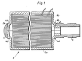
- the embodiment of the arrangement in accordance with the invention shown on the drawings by way of an example consists of a stack of supporting plates 1 with membranes 2 arranged in pairs between the plates.
- the stack is fixed in an enclosure 3 which consists of two enclosure parts 3a and 3b.
- a flange 4a and 4b, respectively, runs along the orifices of the boxlike enclosure parts which are partially cast into a retaining band 5.
- Nipples 6, which lead to a distributing or collecting channel 24 for the said second fluid, are preferably cast in one piece with this retaining band 5.
- these nipples 6 serve as inlet and outlet, respectively, for the dialysis liquid. If instead a haemofilter is concerned, it would be enough with one nipple 6 intended to serve as an outlet for the filtrate.
- the retaining band 5 may be designed in accordance with our Swedish patent application 88.00137-5 submitted at the same time.
- the blood is supplied in a manner known in itself to a flow-through duct formed by through-openings 7 arranged straight through the stack near its one end.
- the blood is withdrawn in a manner known in itself through a flow-through duct formed by through-openings 8 arranged straight through the stack near its other end.
- this supply and withdrawal takes place with the help of blood distributing buttons of the type described in more detail in the above mentioned American patents 3 837 496 and 3 841 491.
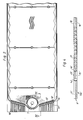
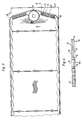
- the dialysis liquid is furnished instead, as can best be seen in figures 3 and 5, through channels 11 originating from the end edges 9 of the supporting plates and open towards the undersides 10 of the plates. At that a seal 13, provided on the other side 12 of the plate, is passed. The dialysis liquid subsequently passes through an opening 14 leading through the plate so as to flow out into channels 15 open towards the top side of the plates. Finally, the dialysis liquid is distributed to both sides of the plates through a second set of through-openings 16. Finally, the dialysis liquid is conducted out in channels 17 distributed over the whole working surface of the plate. The dialysis liquid then leaves the plate via a system of channels which are shown best in figure 4.
- the dialysis liquid this flows first through an opening 16′ passing through the plate into a channel 15′ on the underside 10 of the plate. From there the dialysis liquid flows through a further opening 14′ passing through the plate out into a channel 11′ which lastly opens out at the opposite end edge 9′ of the plate.
- the difference compared at the arrangement according to figure 5 lies primarily in the seal 13′ which here is retracted to a location straight before the channel 15′. In this manner the seals 13 and 13′ can constitute two parts of a seal which extends around the whole working surface of the plate including inlet and outlet openings for the blood.
- This seal thus being in the form of a sealing bead, co-operates with a plain sealing surface provided on the opposite side of the plate, the corresponding sealing components being designated 13a and 13a′.
- Numerals 18 and 18′ respectively, designate a ridge shown schematically as a line provided in the channels 15 and 11′, respectively. This narrow ridge, which appropriately extends up to the surface of the plate, is intended to prevent the membrane being pressed down into these channels. As is evident, these ridges after an interruption for the openings 16 and 16′, extend a short distance inward on the supporting plate up to the actual working pattern of the plate.
- FIG 6 In figure 6 is shown the region adjoining the blood inlet 8 on a larger scale.
- This blood inlet 8 is arranged in the centre of a conical recess 19 which is surrounded by a circular row of bevelled studs 20.
- a great number of hexagonal studs 21 To the right in the figure some through-openings 14 and 16 are shown.
- the working channels 17 are surrounded by alternately wide and narrow ridges 22 and 23, respectively. These are designed appropriately of the same height as the studs 20 and 21.
- every other supporting plate is turned by 180° in its own main plane, that is to say so that the beads 13 and 13′ always point either upwards or downwards. If the beads instead were to be exchanged for plain sealing surfaces, the plates can be turned instead by 180° either round the longitudinal centre axis or the transverse centre axis in order to achieve the same result.
Landscapes
- Chemical & Material Sciences (AREA)
- Chemical Kinetics & Catalysis (AREA)
- Separation Using Semi-Permeable Membranes (AREA)
- External Artificial Organs (AREA)
Applications Claiming Priority (2)
| Application Number | Priority Date | Filing Date | Title |
|---|---|---|---|
| SE8800138 | 1988-01-18 | ||
| SE8800138A SE457605B (sv) | 1988-01-18 | 1988-01-18 | Anordning foer diffusion av aemnen mellan tvaa fluida |
Publications (3)
| Publication Number | Publication Date |
|---|---|
| EP0324922A2 true EP0324922A2 (de) | 1989-07-26 |
| EP0324922A3 EP0324922A3 (en) | 1989-12-13 |
| EP0324922B1 EP0324922B1 (de) | 1992-08-12 |
Family
ID=20371096
Family Applications (1)
| Application Number | Title | Priority Date | Filing Date |
|---|---|---|---|
| EP88119648A Expired EP0324922B1 (de) | 1988-01-18 | 1988-11-25 | Anordnung zur Diffusion von Stoffen zwischen zwei Flüssigkeiten |
Country Status (4)
| Country | Link |
|---|---|
| EP (1) | EP0324922B1 (de) |
| DE (1) | DE3873730T2 (de) |
| ES (1) | ES2034128T3 (de) |
| SE (1) | SE457605B (de) |
Cited By (12)
| Publication number | Priority date | Publication date | Assignee | Title |
|---|---|---|---|---|
| US7105089B2 (en) | 2003-03-13 | 2006-09-12 | 3M Innovative Properties Company | Liquid—liquid extraction system and method |
| US7122709B2 (en) | 2003-03-13 | 2006-10-17 | 3M Innovative Properties Company | Method for obtaining ethanol |
| WO2010139344A1 (de) * | 2009-06-03 | 2010-12-09 | Jan Schultink | Membranmodul und dessen verwendung |
| WO2010151419A1 (en) * | 2009-06-24 | 2010-12-29 | State Of Oregon Acting By And Through The State Board Of Higher Education On Behalf Of Oregon State University | Microfluidic devices for dialysis |
| US9328969B2 (en) | 2011-10-07 | 2016-05-03 | Outset Medical, Inc. | Heat exchange fluid purification for dialysis system |
| US9402945B2 (en) | 2014-04-29 | 2016-08-02 | Outset Medical, Inc. | Dialysis system and methods |
| US9545469B2 (en) | 2009-12-05 | 2017-01-17 | Outset Medical, Inc. | Dialysis system with ultrafiltration control |
| US9895480B2 (en) | 2010-06-07 | 2018-02-20 | Oregon State University | Dialysis system |
| US10105476B2 (en) | 2010-06-07 | 2018-10-23 | Oregon State University | Fluid purification system |
| US11534537B2 (en) | 2016-08-19 | 2022-12-27 | Outset Medical, Inc. | Peritoneal dialysis system and methods |
| US12201762B2 (en) | 2018-08-23 | 2025-01-21 | Outset Medical, Inc. | Dialysis system and methods |
| US12390565B2 (en) | 2019-04-30 | 2025-08-19 | Outset Medical, Inc. | Dialysis systems and methods |
Families Citing this family (3)
| Publication number | Priority date | Publication date | Assignee | Title |
|---|---|---|---|---|
| US7955504B1 (en) | 2004-10-06 | 2011-06-07 | State Of Oregon Acting By And Through The State Board Of Higher Education On Behalf Of Oregon State University | Microfluidic devices, particularly filtration devices comprising polymeric membranes, and method for their manufacture and use |
| US8114276B2 (en) | 2007-10-24 | 2012-02-14 | Baxter International Inc. | Personal hemodialysis system |
| US8580161B2 (en) | 2010-05-04 | 2013-11-12 | State Of Oregon Acting By And Through The State Board Of Higher Education On Behalf Of Oregon State University | Fluidic devices comprising photocontrollable units |
Family Cites Families (6)
| Publication number | Priority date | Publication date | Assignee | Title |
|---|---|---|---|---|
| US3534860A (en) * | 1968-11-29 | 1970-10-20 | Gen Electric | Pressure seal-manifold unit |
| FR2206110B1 (de) * | 1972-11-14 | 1976-04-23 | Rhone Poulenc Ind | |
| US4051041A (en) * | 1973-03-21 | 1977-09-27 | Gambro Ag | Device for diffusion of substances between two fluids through semipermeable membranes |
| SE390109B (sv) * | 1973-09-13 | 1976-12-06 | Paul J Johansson | Dialysanordning for rening av ett medium, foretredesvis blod |
| SE378358B (de) * | 1973-12-10 | 1975-09-01 | Johansson P J | |
| SE7801231L (sv) * | 1978-02-02 | 1979-08-03 | Gambro Ab | Anordning for diffusion av emnen mellan tva fluida atskilda av ett semipermeabelt membran |
-
1988
- 1988-01-18 SE SE8800138A patent/SE457605B/sv not_active IP Right Cessation
- 1988-11-25 DE DE8888119648T patent/DE3873730T2/de not_active Expired - Lifetime
- 1988-11-25 ES ES198888119648T patent/ES2034128T3/es not_active Expired - Lifetime
- 1988-11-25 EP EP88119648A patent/EP0324922B1/de not_active Expired
Cited By (20)
| Publication number | Priority date | Publication date | Assignee | Title |
|---|---|---|---|---|
| US7122709B2 (en) | 2003-03-13 | 2006-10-17 | 3M Innovative Properties Company | Method for obtaining ethanol |
| US7517455B2 (en) | 2003-03-13 | 2009-04-14 | 3M Innovative Properties Company | Liquid-liquid extraction system and method |
| US7105089B2 (en) | 2003-03-13 | 2006-09-12 | 3M Innovative Properties Company | Liquid—liquid extraction system and method |
| WO2010139344A1 (de) * | 2009-06-03 | 2010-12-09 | Jan Schultink | Membranmodul und dessen verwendung |
| WO2010151419A1 (en) * | 2009-06-24 | 2010-12-29 | State Of Oregon Acting By And Through The State Board Of Higher Education On Behalf Of Oregon State University | Microfluidic devices for dialysis |
| US9545469B2 (en) | 2009-12-05 | 2017-01-17 | Outset Medical, Inc. | Dialysis system with ultrafiltration control |
| US11724013B2 (en) | 2010-06-07 | 2023-08-15 | Outset Medical, Inc. | Fluid purification system |
| US10105476B2 (en) | 2010-06-07 | 2018-10-23 | Oregon State University | Fluid purification system |
| US10668201B2 (en) | 2010-06-07 | 2020-06-02 | Oregon State University | Dialysis system |
| US9895480B2 (en) | 2010-06-07 | 2018-02-20 | Oregon State University | Dialysis system |
| US9328969B2 (en) | 2011-10-07 | 2016-05-03 | Outset Medical, Inc. | Heat exchange fluid purification for dialysis system |
| US11305040B2 (en) | 2014-04-29 | 2022-04-19 | Outset Medical, Inc. | Dialysis system and methods |
| US9579440B2 (en) | 2014-04-29 | 2017-02-28 | Outset Medical, Inc. | Dialysis system and methods |
| US9504777B2 (en) | 2014-04-29 | 2016-11-29 | Outset Medical, Inc. | Dialysis system and methods |
| US9402945B2 (en) | 2014-04-29 | 2016-08-02 | Outset Medical, Inc. | Dialysis system and methods |
| US11534537B2 (en) | 2016-08-19 | 2022-12-27 | Outset Medical, Inc. | Peritoneal dialysis system and methods |
| US11951241B2 (en) | 2016-08-19 | 2024-04-09 | Outset Medical, Inc. | Peritoneal dialysis system and methods |
| US12465671B2 (en) | 2016-08-19 | 2025-11-11 | Outset Medical, Inc. | Sterile interface connection of a disposable source of dialysate concentrates |
| US12201762B2 (en) | 2018-08-23 | 2025-01-21 | Outset Medical, Inc. | Dialysis system and methods |
| US12390565B2 (en) | 2019-04-30 | 2025-08-19 | Outset Medical, Inc. | Dialysis systems and methods |
Also Published As
| Publication number | Publication date |
|---|---|
| DE3873730T2 (de) | 1992-12-24 |
| DE3873730D1 (de) | 1992-09-17 |
| ES2034128T3 (es) | 1993-04-01 |
| SE8800138D0 (sv) | 1988-01-18 |
| SE457605B (sv) | 1989-01-16 |
| EP0324922B1 (de) | 1992-08-12 |
| EP0324922A3 (en) | 1989-12-13 |
Similar Documents
| Publication | Publication Date | Title |
|---|---|---|
| EP0324922A2 (de) | Anordnung zur Diffusion von Stoffen zwischen zwei Flüssigkeiten | |
| US4430218A (en) | Separating device for fluids, consisting of support plates and cut sections of a semi-permeable diaphragm | |
| EP0269721B1 (de) | Ultrafiltrationsvorrichtung | |
| EP0066198B1 (de) | Vorrichtung zum Trennen einer Flüssigkeit in zwei Fraktionen | |
| EP0345209A2 (de) | Zweiweg-Ultrafiltrationsvorrichtung | |
| EP0086503B1 (de) | Vorrichtung zur Diffusion von Stoffen zwischen zwei Fluiden durch semipermeable Membranen | |
| CA1044158A (en) | Plate dialyser with improved liquid feed passges | |
| EP0083006B1 (de) | Flachmembran-Trenngerät | |
| CA1089371A (en) | Device for the diffusion of substances between two fluids via semipermeable membranes | |
| DE2028325A1 (de) | Membran-Fluidumdiffusionsaustauschvorrichtung | |
| US3511381A (en) | Dialysis blood distribution grooves | |
| KR20210006889A (ko) | 주입 의료 라인용 필터 | |
| US3516548A (en) | Dialysis means having spacing disks with gratings displaced or twisted in relation to each other | |
| US4786411A (en) | Fluid treatment apparatus with semi-permeable membranes | |
| EP2457641B1 (de) | Verteilerplatten für Flüssigkeitsbehandlungsanordnungen | |
| US3051316A (en) | Exchange apparatus | |
| US4016082A (en) | Device for the diffusion of substances between two fluids via semi-permeable diaphragms | |
| FI63858B (fi) | Anordning foer diffusion av aemnen mellan tvao fluider via semipermeabla membran | |
| US4390424A (en) | Device for diffusing matter between two fluids via semi-permeable diaphragms | |
| EP0078659A3 (de) | Membranfiltrationsvorrichtung | |
| US4422936A (en) | Device for the diffusion of substances between two fluids via semipermeable membranes | |
| EP0358964B1 (de) | Infusions und//oder Injektions-system mit Mehrkammer-Filter und Mehrkammer Anschlussleitung | |
| US3762555A (en) | Supporting plates for the membranes of a dialyzer | |
| US4617119A (en) | Blood exchange apparatus | |
| EP0324919A2 (de) | Eine Anordnung für die Diffusion und/oder Filtration von Substanzen zwischen zwei Fluiden |
Legal Events
| Date | Code | Title | Description |
|---|---|---|---|
| PUAI | Public reference made under article 153(3) epc to a published international application that has entered the european phase |
Free format text: ORIGINAL CODE: 0009012 |
|
| AK | Designated contracting states |
Kind code of ref document: A2 Designated state(s): BE CH DE ES FR GB IT LI NL |
|
| PUAL | Search report despatched |
Free format text: ORIGINAL CODE: 0009013 |
|
| AK | Designated contracting states |
Kind code of ref document: A3 Designated state(s): BE CH DE ES FR GB IT LI NL |
|
| 17P | Request for examination filed |
Effective date: 19900523 |
|
| RAP1 | Party data changed (applicant data changed or rights of an application transferred) |
Owner name: GAMBRO AG |
|
| 17Q | First examination report despatched |
Effective date: 19911014 |
|
| GRAA | (expected) grant |
Free format text: ORIGINAL CODE: 0009210 |
|
| ITF | It: translation for a ep patent filed | ||
| AK | Designated contracting states |
Kind code of ref document: B1 Designated state(s): BE CH DE ES FR GB IT LI NL |
|
| REF | Corresponds to: |
Ref document number: 3873730 Country of ref document: DE Date of ref document: 19920917 |
|
| ET | Fr: translation filed | ||
| REG | Reference to a national code |
Ref country code: ES Ref legal event code: FG2A Ref document number: 2034128 Country of ref document: ES Kind code of ref document: T3 |
|
| PLBE | No opposition filed within time limit |
Free format text: ORIGINAL CODE: 0009261 |
|
| STAA | Information on the status of an ep patent application or granted ep patent |
Free format text: STATUS: NO OPPOSITION FILED WITHIN TIME LIMIT |
|
| 26N | No opposition filed | ||
| REG | Reference to a national code |
Ref country code: GB Ref legal event code: IF02 |
|
| PGFP | Annual fee paid to national office [announced via postgrant information from national office to epo] |
Ref country code: BE Payment date: 20021203 Year of fee payment: 15 |
|
| PGFP | Annual fee paid to national office [announced via postgrant information from national office to epo] |
Ref country code: NL Payment date: 20031002 Year of fee payment: 16 |
|
| PG25 | Lapsed in a contracting state [announced via postgrant information from national office to epo] |
Ref country code: BE Free format text: LAPSE BECAUSE OF NON-PAYMENT OF DUE FEES Effective date: 20031130 |
|
| BERE | Be: lapsed |
Owner name: *GAMBRO A.G. Effective date: 20031130 |
|
| PGFP | Annual fee paid to national office [announced via postgrant information from national office to epo] |
Ref country code: GB Payment date: 20041004 Year of fee payment: 17 |
|
| PGFP | Annual fee paid to national office [announced via postgrant information from national office to epo] |
Ref country code: FR Payment date: 20041105 Year of fee payment: 17 |
|
| PGFP | Annual fee paid to national office [announced via postgrant information from national office to epo] |
Ref country code: ES Payment date: 20041119 Year of fee payment: 17 |
|
| PGFP | Annual fee paid to national office [announced via postgrant information from national office to epo] |
Ref country code: DE Payment date: 20041130 Year of fee payment: 17 |
|
| PGFP | Annual fee paid to national office [announced via postgrant information from national office to epo] |
Ref country code: CH Payment date: 20050107 Year of fee payment: 17 |
|
| PG25 | Lapsed in a contracting state [announced via postgrant information from national office to epo] |
Ref country code: NL Free format text: LAPSE BECAUSE OF NON-PAYMENT OF DUE FEES Effective date: 20050601 |
|
| NLV4 | Nl: lapsed or anulled due to non-payment of the annual fee |
Effective date: 20050601 |
|
| PG25 | Lapsed in a contracting state [announced via postgrant information from national office to epo] |
Ref country code: IT Free format text: LAPSE BECAUSE OF NON-PAYMENT OF DUE FEES Effective date: 20051125 Ref country code: GB Free format text: LAPSE BECAUSE OF NON-PAYMENT OF DUE FEES Effective date: 20051125 |
|
| PG25 | Lapsed in a contracting state [announced via postgrant information from national office to epo] |
Ref country code: ES Free format text: LAPSE BECAUSE OF NON-PAYMENT OF DUE FEES Effective date: 20051126 |
|
| PG25 | Lapsed in a contracting state [announced via postgrant information from national office to epo] |
Ref country code: LI Free format text: LAPSE BECAUSE OF NON-PAYMENT OF DUE FEES Effective date: 20051130 Ref country code: CH Free format text: LAPSE BECAUSE OF NON-PAYMENT OF DUE FEES Effective date: 20051130 |
|
| PG25 | Lapsed in a contracting state [announced via postgrant information from national office to epo] |
Ref country code: DE Free format text: LAPSE BECAUSE OF NON-PAYMENT OF DUE FEES Effective date: 20060601 |
|
| REG | Reference to a national code |
Ref country code: CH Ref legal event code: PL |
|
| GBPC | Gb: european patent ceased through non-payment of renewal fee |
Effective date: 20051125 |
|
| PG25 | Lapsed in a contracting state [announced via postgrant information from national office to epo] |
Ref country code: FR Free format text: LAPSE BECAUSE OF NON-PAYMENT OF DUE FEES Effective date: 20060731 |
|
| REG | Reference to a national code |
Ref country code: FR Ref legal event code: ST Effective date: 20060731 |
|
| REG | Reference to a national code |
Ref country code: ES Ref legal event code: FD2A Effective date: 20051126 |