EP0324967A2 - Multiplicateur de pente compensé linéairement - Google Patents
Multiplicateur de pente compensé linéairement Download PDFInfo
- Publication number
- EP0324967A2 EP0324967A2 EP88121488A EP88121488A EP0324967A2 EP 0324967 A2 EP0324967 A2 EP 0324967A2 EP 88121488 A EP88121488 A EP 88121488A EP 88121488 A EP88121488 A EP 88121488A EP 0324967 A2 EP0324967 A2 EP 0324967A2
- Authority
- EP
- European Patent Office
- Prior art keywords
- input
- differential amplifier
- amplifier
- differential
- output
- Prior art date
- Legal status (The legal status is an assumption and is not a legal conclusion. Google has not performed a legal analysis and makes no representation as to the accuracy of the status listed.)
- Withdrawn
Links
Images
Classifications
-
- G—PHYSICS
- G06—COMPUTING OR CALCULATING; COUNTING
- G06G—ANALOGUE COMPUTERS
- G06G7/00—Devices in which the computing operation is performed by varying electric or magnetic quantities
- G06G7/12—Arrangements for performing computing operations, e.g. operational amplifiers specially adapted therefor
- G06G7/16—Arrangements for performing computing operations, e.g. operational amplifiers specially adapted therefor for multiplication or division
- G06G7/163—Arrangements for performing computing operations, e.g. operational amplifiers specially adapted therefor for multiplication or division using a variable impedance controlled by one of the input signals, variable amplification or transfer function
Definitions
- control currents for the two differential amplifiers are kept very small or the control currents are of the same size (the control currents here are those which are common through the emitter connections and thus determine the gain determine the currents). As the deviation increases, the non-linearity increases many times with higher values for the control currents.
- the cause of this disruptive effect is the internal resistance in the emitter that occurs in real transistors, the so-called emitter path resistance (referred to in the English-language literature as emitter bulk resistance).
- This resistor (R-Eb) acts in principle like an emitter resistor and causes a negative feedback dependent on the product of control current times R-Eb within the two differential amplifiers from "2" and thus dependent transmission characteristics. This means that the transmission characteristics only compensate if the product of control current times R-Eb is the same for both differential amplifiers from "2". Otherwise, a non-linearity depends on the magnitude of the deviation, which causes cubic distortions to occur when AC voltages are used as the input signal.
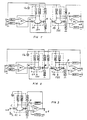
- the following cause is responsible for the fact that the compensation of the R-Eb according to FIG. 1 is not 100%:
- the disturbing negative feedback acts not only for the signals present at the first inputs (A, C) of the two differential amplifiers, but also equally the compensation signals present at the respective second inputs (B, D) and therefore a residual gain error ⁇ V-R remains.
- the effect of the ⁇ V-R depends on the respective control currents at which the two voltage dividers (Rb1, Rb2 and Rd1, Rd2) are set to the lowest non-linearity and increases with larger maximum values for the two control currents.
- the compensation of the R-Eb shown in FIG. 2 has an advantage over that shown in FIG.
- the emitter path resistance compensations shown in FIGS. 1 and 2 also reduce or eliminate the non-linearity of the overall control current gain characteristic, which is also due to the fact that with increasing control currents the negative feedback increases in the two differential amplifiers.
Landscapes
- Engineering & Computer Science (AREA)
- Physics & Mathematics (AREA)
- Mathematical Physics (AREA)
- Theoretical Computer Science (AREA)
- Power Engineering (AREA)
- Software Systems (AREA)
- Computer Hardware Design (AREA)
- General Physics & Mathematics (AREA)
- Amplifiers (AREA)
- Control Of Amplification And Gain Control (AREA)
Applications Claiming Priority (2)
| Application Number | Priority Date | Filing Date | Title |
|---|---|---|---|
| AT342287A AT392709B (de) | 1987-12-23 | 1987-12-23 | Elektronische multiplizierschaltung |
| AT3422/87 | 1987-12-23 |
Publications (2)
| Publication Number | Publication Date |
|---|---|
| EP0324967A2 true EP0324967A2 (fr) | 1989-07-26 |
| EP0324967A3 EP0324967A3 (fr) | 1990-09-26 |
Family
ID=3550283
Family Applications (1)
| Application Number | Title | Priority Date | Filing Date |
|---|---|---|---|
| EP19880121488 Withdrawn EP0324967A3 (fr) | 1987-12-23 | 1988-12-22 | Multiplicateur de pente compensé linéairement |
Country Status (2)
| Country | Link |
|---|---|
| EP (1) | EP0324967A3 (fr) |
| AT (1) | AT392709B (fr) |
Cited By (1)
| Publication number | Priority date | Publication date | Assignee | Title |
|---|---|---|---|---|
| US6043768A (en) * | 1996-02-16 | 2000-03-28 | Johannes Heidenhain Gmbh | Device and method for switching between different operating modes of a transducer |
Family Cites Families (2)
| Publication number | Priority date | Publication date | Assignee | Title |
|---|---|---|---|---|
| US3562553A (en) * | 1968-10-21 | 1971-02-09 | Allen R Roth | Multiplier circuit |
| US4572975A (en) * | 1984-04-02 | 1986-02-25 | Precision Monolithics, Inc. | Analog multiplier with improved linearity |
-
1987
- 1987-12-23 AT AT342287A patent/AT392709B/de not_active IP Right Cessation
-
1988
- 1988-12-22 EP EP19880121488 patent/EP0324967A3/fr not_active Withdrawn
Cited By (1)
| Publication number | Priority date | Publication date | Assignee | Title |
|---|---|---|---|---|
| US6043768A (en) * | 1996-02-16 | 2000-03-28 | Johannes Heidenhain Gmbh | Device and method for switching between different operating modes of a transducer |
Also Published As
| Publication number | Publication date |
|---|---|
| AT392709B (de) | 1991-05-27 |
| ATA342287A (de) | 1990-10-15 |
| EP0324967A3 (fr) | 1990-09-26 |
Similar Documents
| Publication | Publication Date | Title |
|---|---|---|
| DE69431905T2 (de) | Leitungstreiber mit adaptiver ausgangsimpedanz | |
| DE60132860T2 (de) | Transkonduktanzverstärker | |
| DE2429953B2 (de) | Schaltungsanordnung zur Verarbeitung physiologischer Meßsignale | |
| DE102007011715B4 (de) | Verstärkeranordnung zum Verstärken eines Signals | |
| EP0365085B1 (fr) | Circuit de commande de l'amplitude d'un signal | |
| DE3108617A1 (de) | "verstaerkungssteuerschaltung" | |
| DE69201297T2 (de) | Ultraschnelle Differenzverstärker. | |
| US6023194A (en) | Amplifier with reduced input capacitance | |
| DE19518734C1 (de) | Transimpedanzverstärkerschaltung | |
| US5057716A (en) | Linearly compensated slope multiplier | |
| EP0351639A2 (fr) | Circuit d'entrée pour amplificateur haute fréquence | |
| DE3856194T2 (de) | Verstärkerschaltung und mit der Verstärkerschaltung versehene Wiedergabeanordnung | |
| EP0324967A2 (fr) | Multiplicateur de pente compensé linéairement | |
| DE102010027567B4 (de) | Tastkopf-System mit verschiedenen Verstärkern für die hochfrequente und niederfrequente Komponente | |
| DE69838349T2 (de) | Signalumwandler für Röhrenverstärker | |
| DE2755827A1 (de) | Schaltungsanordnung mit einem durch eine steuergleichspannung veraenderbaren frequenzgang | |
| DE3228785C2 (fr) | ||
| EP0691734B1 (fr) | Circuit amplificateur pour signaux à haute fréquence | |
| US5394113A (en) | High impedance low-distortion linear amplifier | |
| DE3525066C1 (de) | Verstaerker mit steuerbarer Verstaerkung | |
| DE3724980A1 (de) | Spannungswiederholerschaltung fuer eine ohmsche komponente aufweisende last mit kompensation der oberwellenverzerrung | |
| DE3124328C2 (de) | Variabler aktiver Entzerrer | |
| DE19637292B4 (de) | Verstärkerschaltung, insbesondere zur Verstärkung von Audiosignalen und Audioverstärker | |
| DE1927587C3 (de) | Breitbandverstaerker,vorzugsweise Leitungsverstaerker der Traegerfrequenztechnik,bestehend aus einem Verstaerker und einem vorgeschalteten Stellglied | |
| DE69432254T2 (de) | Differentielle niederfrequenz-leitungsempfänger |
Legal Events
| Date | Code | Title | Description |
|---|---|---|---|
| PUAI | Public reference made under article 153(3) epc to a published international application that has entered the european phase |
Free format text: ORIGINAL CODE: 0009012 |
|
| AK | Designated contracting states |
Kind code of ref document: A2 Designated state(s): BE CH DE ES FR GB GR IT LI LU NL SE |
|
| RBV | Designated contracting states (corrected) |
Designated state(s): CH DE ES FR GB IT LI LU NL SE |
|
| 17P | Request for examination filed |
Effective date: 19900310 |
|
| PUAL | Search report despatched |
Free format text: ORIGINAL CODE: 0009013 |
|
| AK | Designated contracting states |
Kind code of ref document: A3 Designated state(s): BE CH DE ES FR GB GR IT LI LU NL SE |
|
| STAA | Information on the status of an ep patent application or granted ep patent |
Free format text: STATUS: THE APPLICATION IS DEEMED TO BE WITHDRAWN |
|
| 18D | Application deemed to be withdrawn |
Effective date: 19930701 |