EP0325021A2 - Circulation system and method for reducing foaming in the dampening system of a printing press - Google Patents
Circulation system and method for reducing foaming in the dampening system of a printing press Download PDFInfo
- Publication number
- EP0325021A2 EP0325021A2 EP88307801A EP88307801A EP0325021A2 EP 0325021 A2 EP0325021 A2 EP 0325021A2 EP 88307801 A EP88307801 A EP 88307801A EP 88307801 A EP88307801 A EP 88307801A EP 0325021 A2 EP0325021 A2 EP 0325021A2
- Authority
- EP
- European Patent Office
- Prior art keywords
- wetting fluid
- return conduit
- orifice
- outlet
- venturi tube
- Prior art date
- Legal status (The legal status is an assumption and is not a legal conclusion. Google has not performed a legal analysis and makes no representation as to the accuracy of the status listed.)
- Withdrawn
Links
- 238000005187 foaming Methods 0.000 title claims abstract description 16
- 238000000034 method Methods 0.000 title claims description 12
- 239000012530 fluid Substances 0.000 claims abstract description 104
- 238000009736 wetting Methods 0.000 claims abstract description 100
- 238000001914 filtration Methods 0.000 claims 6
- 238000013022 venting Methods 0.000 claims 3
- KFZMGEQAYNKOFK-UHFFFAOYSA-N Isopropanol Chemical compound CC(C)O KFZMGEQAYNKOFK-UHFFFAOYSA-N 0.000 abstract description 24
- XLYOFNOQVPJJNP-UHFFFAOYSA-N water Substances O XLYOFNOQVPJJNP-UHFFFAOYSA-N 0.000 abstract description 7
- 239000006260 foam Substances 0.000 description 6
- 230000005484 gravity Effects 0.000 description 5
- 238000001816 cooling Methods 0.000 description 4
- 238000005259 measurement Methods 0.000 description 3
- 239000006185 dispersion Substances 0.000 description 2
- 239000000428 dust Substances 0.000 description 2
- 230000000694 effects Effects 0.000 description 2
- 239000000835 fiber Substances 0.000 description 2
- 239000000976 ink Substances 0.000 description 2
- 239000007788 liquid Substances 0.000 description 2
- 239000000203 mixture Substances 0.000 description 2
- 238000005057 refrigeration Methods 0.000 description 2
- 239000002518 antifoaming agent Substances 0.000 description 1
- 230000000903 blocking effect Effects 0.000 description 1
- 230000003247 decreasing effect Effects 0.000 description 1
- 230000006866 deterioration Effects 0.000 description 1
- 238000005516 engineering process Methods 0.000 description 1
- 238000004880 explosion Methods 0.000 description 1
- 229920001821 foam rubber Polymers 0.000 description 1
- 230000005802 health problem Effects 0.000 description 1
- 238000009434 installation Methods 0.000 description 1
- 238000011176 pooling Methods 0.000 description 1
- 238000009420 retrofitting Methods 0.000 description 1
- 239000000126 substance Substances 0.000 description 1
- 239000004094 surface-active agent Substances 0.000 description 1
Images

Classifications
-
- B—PERFORMING OPERATIONS; TRANSPORTING
- B41—PRINTING; LINING MACHINES; TYPEWRITERS; STAMPS
- B41F—PRINTING MACHINES OR PRESSES
- B41F33/00—Indicating, counting, warning, control or safety devices
- B41F33/0054—Devices for controlling dampening
Definitions
- the present invention relates to the dampening systems of printing presses.
- a dampening system is used to provide a thin layer of a wetting fluid to the press plates.
- the wetting fluid is usually water, or a water, chemical and isopropanol mixture. Isopropanol is used to reduce the surface tension of the wetting fluid, allowing it to be spread more easily and thinly on the press plate.
- the dampening system wets down the plate before the ink is applied to the plate to selectively prevent inking of the press plate.
- the dampening system will include an open fountain pan having an inlet and an outlet through which flows a stream of the wetting fluid and in which rotates a water pan roller.
- the water pan roller picks up a film of the wetting fluid and transfers this film to a contacting counter-rotating roller to make the film thinner; at least one more roller is usually used to further thin the wetting fluid before it is applied to a press plate.
- the wetting fluid is drawn from the fountain pan through return tubing by suction which is created by a venturi in a cooling unit.
- the wetting fluid is passed through a filter to remove lint, dust, fibers and ink from the wetting fluid, and then cooled in a refrigerated reservoir in the cooling unit.
- the wetting fluid is then pumped from the reservoir to a flow divider which directs a portion of the wetting fluid back to the fountain pan, and a portion of the wetting fluid through the venturi to create suction in the return conduit.
- the venturi has a single orifice at its throat sized to provide the maximum amount of vacuum for the pump flow rate.
- a wetting fluid specific gravity measuring apparatus and isopropanol metering unit is provided between the pump outlet and the fountain pan to maintain a predetermined mixture of water and isopropanol in the wetting fluid.
- the most severe problem of air entrainment in the circulation system is that it can cause foaming of the wetting fluid as it passes through the venturi and the filters.
- Foam in the wetting fluid creates immediate print quality problems.
- Foam in the dampening system, particularly in the fountain pan impedes the smooth dispersion of the wetting fluid on the press plate, giving unacceptably poor print quality.
- the foam will cause false measurements in the wetting fluid specific gravity measurement apparatus.
- the wetting fluid specific gravity measurement apparatus will be measuring a wetting fluid having a lower specific gravity due to the entrained bubbles in the wetting fluid, and will thus meter a lower quantity of isopropanol into the system than desired, causing a further deterioration in wetting fluid dispersion and print quality.
- the fountain pan outlet size might be increased in diameter; however, this would involve expensive retrofitting of the existing press hardware.
- a defoaming agent might be added to the wetting fluid; however, this could negatively affect the qualities of the etch solution.
- a reduction of the wetting fluid flow rate can reduce the foaming in the system.
- a reduced flow rate causes other problems.
- the constant contact between the rotating rolls generates a great deal of frictional heat, which causes a substantial temperature differential in the wetting fluid between the inlet and outlet of the fountain pan.
- This temperature differential in the wetting fluid from one end of the pan to the other causes a viscosity change in the wetting fluid as it passes through the pan. Consequently, more wetting fluid will be picked up by the pan rollers at the inlet side than at the outlet side of the pan, causing print quality variations.
- the lower the flow rate of the wetting fluid through the fountain pan the more severe this problem becomes.
- the uneven spreading associated with low wetting fluid flow rates may induce the pressman to increase the amount of isopropanol in the wetting fluid in an attempt to achieve better spreading of the wetting fluid.
- high levels of isopropanol in the wetting fluid pose potential health problems for the pressmen, may violate emissions control standards, and increase fire and explosion hazards.
- a circulation system which comprises a fountain pan having at each end an inlet and an outlet through which flows a wetting fluid.
- a return conduit is attached to the fountain pan outlet; this return conduit has a vent downstream of the outlet which allows entrained air to escape from the conduit.
- the return conduit has preferably at least a 5/8 inch inner diameter.
- the vent is located between closely adjacent to up to about 24 inches downstream of the outlet, preferably in a vertical section of the conduit.
- a tube which leads back up to and into the fountain pan may be mounted in the vent to recycle liquid to the fountain tray outlet.
- a sump which may comprise a portion of the return conduit formed into an inverted U-shaped loop, may be provided downstream of the vent at the lowest point of the return conduit.
- Wetting fluid is drawn from the sump and return conduit by a venturi tube, and flowed through a filter unit.
- the venturi tube provides a vacuum to the sump which calibrated to be sufficient to draw wetting fluid from the sump, yet which does not entrain air into the wetting fluid at the fountain pan outlet.
- the venturi tube has an inlet with a first orifice and a throat with a second orifice.
- the return conduit is connected to the venturi downstream of the second orifice, and the vacuum created in the return conduit pulls the wetting fluid from the sump and return conduit.
- the ratio of the inner diameter of the first orifice to the inner diameter of the second orifice is about 0.5 to 1.25.
- a reservoir having a cooling means within it receives the wetting fluid from the filter.
- a pump then flows the wetting fluid from the reservoir to a flow divider which sends a portion of the pumped fluid to the venturi to induce the vacuum in the return conduit, and a portion of the fluid back to the fountain tray inlet for application to the press plate.
- the circulation system 10 comprises a standard fountain pan 20 having an inlet 22 and an outlet 24 at opposite ends of the fountain pan 20. Wetting fluid in the fountain pan is drained through outlet 24 into return conduit 26, which is typically a flexible tubing which preferably has an inner diameter of at least 5/8 inch to allow a downward fluid flow as well as a upward flow of any trapped air bubbles.
- Vent 28 is located in return conduit 26. Vent 28 serves to vent air which is drawn into conduit 26 through the outlet 24, preventing air bubbles from becoming trapped in the conduit 26 and blocking the flow of the wetting fluid, and eliminating these bubbles from the circulation system before they are passed through a venturi tube 38 where they would create foam in the wetting fluid.
- vent 28 is provided in a vertical section of the return conduit 26, at a location adjacent to or up to 24 inches downstream of the outlet 24.
- the vent may also be located in a horizontal or angled section of the return conduit on the upper surface of the conduit.
- Vent 28 may be take any number of embodiments, although it has been found that the easiest vent 28 to install and remove is one such as that shown in FIG. 4, namely a sleeve 30 having an outwardly directed vent stem 32.
- Sleeve 30 is sized such that conduit 26 may be pushed onto each end of the sleeve 30 and clamped. Vent tubing 34 leading to and feeding into fountain tray 20 from vent stem 32 allows any liquid or foam which is vented to be recirculated in the circulation system.
- Return conduit 26 will typically continue from the vent 28 downward to floor level.
- a closed sump 36 such as the inverted U-shaped loop 37 in return conduit 26 is provided at this low point in the return conduit. Sump 36 promotes the exhaustion of air in the circulating system during initial start up, as will be described later in this section.
- Venturi tube 38 is typically mounted at an elevation above the sump 36.
- the suction provided by venturi tube 38 at return inlet 40 draws the wetting fluid from the sump 36 through the return conduit 26.
- the venturi 38 then propels the wetting fluid through a filter means 41 such as a foam rubber filter to remove fibers, lint, dust and other debris collected in the wetting fluid.
- the filter 41 may be submerged in a cooling reservoir 42, as shown in FIG. 1.
- Reservoir 42 may be provided with refrigeration coils 44 and a refrigeration system to cool the wetting fluid.
- Wetting fluid is withdrawn from the reservoir 42 by pump 45, which is typically a constant pressure pump such as a centrifugal pump.
- the wetting fluid is flowed to flow divider 46, which directs a portion of the pump output to the venturi tube 38 and a portion of the pump output to feed line 60 leading to the inlet 22 of fountain pan 20.
- a film of wetting fluid is collected by rollers 47 from fountain pan 20 and applied to press plate roller 48.
- the present invention uses a venturi tube calibrated to provide a vacuum sufficient to draw the wetting fluid from its lowest point in the return line, without entraining air into the circulating system from the fountain pan.
- a venturi tube using a single orifice can be so designed and calibrated, and is regarded as part of the present invention.
- a venturi tube having two orifices allows a greater ability to calibrate the amount of vacuum to the particular layout of the return conduit.
- venturi tube 38 has a fluid inlet 50 with a first aperture 52 mounted therein.
- the second aperture may comprise the throat 54 of venturi tube 38.
- the ratio of the inner diameter of the first orifice to the inner diamenter of the second orifice is about 0.5 to 1.25, allowing for a wide range of calibration of vaccum.
- the first aperture has a inner diameter which is between .15 to .25 inches
- the throat 54 of the venturi has an orifice size which is between .20 to .30 inches.
- the preferred orifice sizes are respectively .20 inches for the first orifice and .25 inches for the throat orifice. It has been found that these orifices in combination provide a balanced amount of suction at the return inlet 40 so that the wetting fluid can be flowed through the system from the sump 36 without drawing air into the circulation system.
- a wetting fluid specific gravity measuring apparatus and isopropanol metering system 56 such as the Balcontrol manufactured and sold by the Baldwin Technology Corporation, Stamford, Connecticut may be mounted at the flow divider 46.
- the circulating system of the present invention has been found to eliminate problems of foaming found in the prior art systems, since the vent 28 allows entrained air to escape from the system before it is turbulently agitated in the the venturi, filter and pump.
- the double orifice venturi tube provides a reduced suction in the return line over prior art venturi tubes having a single orifice designed for maximum suction; this reduced suction provides sufficient suction to draw the wetting fluid through the sump and return conduit, yet is not so powerful as to entrain air into the wetting fluid in the system.
- the circulating system 10 has allowed fountain pan flow rates to be increased from the about 0.25 to 0.3 gallons per minute (GPM) flow rates achieved by the prior art systems to about 0.5 to 0.7 GPM, without the problems of foaming and flooding which would otherwise have occurred at such higher flow rates in the prior art devices.
- GPM gallons per minute
- the temperature increase from the inlet to the outlet of the fountain pan is decreased to about one half of the temperature increase of the prior art systems.
- the sump 36 minimizes problems of foaming during start-up of the circulating system 10.
- the sump 36 provides a pooling point for the wetting fluid and an additional pressure drop in the return conduit line during start-up so that the system can begin flowing wetting fluid to the fountain pan 20 without having an immediate intake of air to the circulation system 10 from the fountain pan outlet 24.
Landscapes
- Rotary Presses (AREA)
- Ink Jet (AREA)
Abstract
Description
- The present invention relates to the dampening systems of printing presses.
- In high speed printing presses, such as web offset lithographic presses, a dampening system is used to provide a thin layer of a wetting fluid to the press plates. The wetting fluid is usually water, or a water, chemical and isopropanol mixture. Isopropanol is used to reduce the surface tension of the wetting fluid, allowing it to be spread more easily and thinly on the press plate. The dampening system wets down the plate before the ink is applied to the plate to selectively prevent inking of the press plate.
- Typically the dampening system will include an open fountain pan having an inlet and an outlet through which flows a stream of the wetting fluid and in which rotates a water pan roller. The water pan roller picks up a film of the wetting fluid and transfers this film to a contacting counter-rotating roller to make the film thinner; at least one more roller is usually used to further thin the wetting fluid before it is applied to a press plate.
- In dampening systems known in the industry, the wetting fluid is drawn from the fountain pan through return tubing by suction which is created by a venturi in a cooling unit. The wetting fluid is passed through a filter to remove lint, dust, fibers and ink from the wetting fluid, and then cooled in a refrigerated reservoir in the cooling unit. The wetting fluid is then pumped from the reservoir to a flow divider which directs a portion of the wetting fluid back to the fountain pan, and a portion of the wetting fluid through the venturi to create suction in the return conduit. The venturi has a single orifice at its throat sized to provide the maximum amount of vacuum for the pump flow rate. A wetting fluid specific gravity measuring apparatus and isopropanol metering unit is provided between the pump outlet and the fountain pan to maintain a predetermined mixture of water and isopropanol in the wetting fluid.
- It has been found with such known dampening systems that foam and bubbles will form in the circulation system. It often happens that air above the open fountain pan will be drawn into the fountain pan outlet and collect in the circulation system. This leads to two problems.
- The most severe problem of air entrainment in the circulation system is that it can cause foaming of the wetting fluid as it passes through the venturi and the filters. Foam in the wetting fluid creates immediate print quality problems. Foam in the dampening system, particularly in the fountain pan, impedes the smooth dispersion of the wetting fluid on the press plate, giving unacceptably poor print quality. In addition, the foam will cause false measurements in the wetting fluid specific gravity measurement apparatus. The wetting fluid specific gravity measurement apparatus will be measuring a wetting fluid having a lower specific gravity due to the entrained bubbles in the wetting fluid, and will thus meter a lower quantity of isopropanol into the system than desired, causing a further deterioration in wetting fluid dispersion and print quality.
- The other problem of air entrainment into the system is the potential for creating an air bubble within the return tubing which will impede the draining of the wetting fluid from the fountain pan, causing overflows and flooding of the press room floor.
- It should be appreciated that the aforementioned foaming problems are most prevalent where there are reduced quantities of isopropanol in the wetting fluid, because the surfactant effect of isopropanol in the wetting fluid reduces foaming problems. Nevertheless, it has been found that foaming occurs even with higher isopropanol concentrations.
- Several solutions to these problems have been considered. For example the fountain pan outlet size might be increased in diameter; however, this would involve expensive retrofitting of the existing press hardware. A defoaming agent might be added to the wetting fluid; however, this could negatively affect the qualities of the etch solution.
- A reduction of the wetting fluid flow rate can reduce the foaming in the system. However, such a reduced flow rate causes other problems. The constant contact between the rotating rolls generates a great deal of frictional heat, which causes a substantial temperature differential in the wetting fluid between the inlet and outlet of the fountain pan. This temperature differential in the wetting fluid from one end of the pan to the other causes a viscosity change in the wetting fluid as it passes through the pan. Consequently, more wetting fluid will be picked up by the pan rollers at the inlet side than at the outlet side of the pan, causing print quality variations. The lower the flow rate of the wetting fluid through the fountain pan, the more severe this problem becomes. Furthermore, the uneven spreading associated with low wetting fluid flow rates may induce the pressman to increase the amount of isopropanol in the wetting fluid in an attempt to achieve better spreading of the wetting fluid. However, high levels of isopropanol in the wetting fluid pose potential health problems for the pressmen, may violate emissions control standards, and increase fire and explosion hazards.
- It is an object of the present invention to provide a circulation system and method for reducing foaming in the dampening system of a printing press. It is a further object of the invention to provide such reduced foaming at higher flow rates than has hereto been possible.
- These objects, and other objects which will become apparent from the description that follows, are achieved by a circulation system which comprises a fountain pan having at each end an inlet and an outlet through which flows a wetting fluid. A return conduit is attached to the fountain pan outlet; this return conduit has a vent downstream of the outlet which allows entrained air to escape from the conduit. The return conduit has preferably at least a 5/8 inch inner diameter. The vent is located between closely adjacent to up to about 24 inches downstream of the outlet, preferably in a vertical section of the conduit. A tube which leads back up to and into the fountain pan may be mounted in the vent to recycle liquid to the fountain tray outlet. A sump, which may comprise a portion of the return conduit formed into an inverted U-shaped loop, may be provided downstream of the vent at the lowest point of the return conduit. Wetting fluid is drawn from the sump and return conduit by a venturi tube, and flowed through a filter unit. The venturi tube provides a vacuum to the sump which calibrated to be sufficient to draw wetting fluid from the sump, yet which does not entrain air into the wetting fluid at the fountain pan outlet. The venturi tube has an inlet with a first orifice and a throat with a second orifice. The return conduit is connected to the venturi downstream of the second orifice, and the vacuum created in the return conduit pulls the wetting fluid from the sump and return conduit. The ratio of the inner diameter of the first orifice to the inner diameter of the second orifice is about 0.5 to 1.25.
- A reservoir having a cooling means within it receives the wetting fluid from the filter. A pump then flows the wetting fluid from the reservoir to a flow divider which sends a portion of the pumped fluid to the venturi to induce the vacuum in the return conduit, and a portion of the fluid back to the fountain tray inlet for application to the press plate.
-
- FIG. 1 is a schematic of the circulating system embodying the invention.
- FIG. 2 is a perspective view of the circulating system embodying the invention.
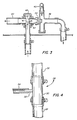
- FIG. 3 is a cross sectional view of the venturi tube embodying the invention.
- FIG. 4 is a cross sectional view of an embodiment of the vent of the present invention.
- The invention will now be illustrated further with respect to the drawings.
- With reference to FIGS. 1 and 2, the
circulation system 10 comprises astandard fountain pan 20 having aninlet 22 and anoutlet 24 at opposite ends of thefountain pan 20. Wetting fluid in the fountain pan is drained throughoutlet 24 intoreturn conduit 26, which is typically a flexible tubing which preferably has an inner diameter of at least 5/8 inch to allow a downward fluid flow as well as a upward flow of any trapped air bubbles. - Vent 28 is located in
return conduit 26.Vent 28 serves to vent air which is drawn intoconduit 26 through theoutlet 24, preventing air bubbles from becoming trapped in theconduit 26 and blocking the flow of the wetting fluid, and eliminating these bubbles from the circulation system before they are passed through aventuri tube 38 where they would create foam in the wetting fluid. Preferably,vent 28 is provided in a vertical section of thereturn conduit 26, at a location adjacent to or up to 24 inches downstream of theoutlet 24. However, the vent may also be located in a horizontal or angled section of the return conduit on the upper surface of the conduit. -
Vent 28 may be take any number of embodiments, although it has been found that theeasiest vent 28 to install and remove is one such as that shown in FIG. 4, namely asleeve 30 having an outwardly directedvent stem 32.Sleeve 30 is sized such thatconduit 26 may be pushed onto each end of thesleeve 30 and clamped.Vent tubing 34 leading to and feeding intofountain tray 20 from vent stem 32 allows any liquid or foam which is vented to be recirculated in the circulation system. - Return
conduit 26 will typically continue from thevent 28 downward to floor level. Aclosed sump 36 such as the invertedU-shaped loop 37 inreturn conduit 26 is provided at this low point in the return conduit.Sump 36 promotes the exhaustion of air in the circulating system during initial start up, as will be described later in this section. - Return
conduit 26 leads fromsump 36 toventuri tube 38, which is shown in detail in FIG. 3.Venturi tube 38 is typically mounted at an elevation above thesump 36. The suction provided byventuri tube 38 atreturn inlet 40 draws the wetting fluid from thesump 36 through thereturn conduit 26. Theventuri 38 then propels the wetting fluid through a filter means 41 such as a foam rubber filter to remove fibers, lint, dust and other debris collected in the wetting fluid. Thefilter 41 may be submerged in a coolingreservoir 42, as shown in FIG. 1.Reservoir 42 may be provided withrefrigeration coils 44 and a refrigeration system to cool the wetting fluid. Wetting fluid is withdrawn from thereservoir 42 bypump 45, which is typically a constant pressure pump such as a centrifugal pump. The wetting fluid is flowed to flowdivider 46, which directs a portion of the pump output to theventuri tube 38 and a portion of the pump output to feedline 60 leading to theinlet 22 offountain pan 20. A film of wetting fluid is collected byrollers 47 fromfountain pan 20 and applied to pressplate roller 48. - In contrast to prior art circulating systems in which the venturi tube was designed to give a maximum vacuum effect, the present invention uses a venturi tube calibrated to provide a vacuum sufficient to draw the wetting fluid from its lowest point in the return line, without entraining air into the circulating system from the fountain pan. A venturi tube using a single orifice can be so designed and calibrated, and is regarded as part of the present invention. However, a venturi tube having two orifices allows a greater ability to calibrate the amount of vacuum to the particular layout of the return conduit.
- In the preferred embodiment,
venturi tube 38, as shown in FIG. 3, has afluid inlet 50 with afirst aperture 52 mounted therein. The second aperture may comprise thethroat 54 ofventuri tube 38. The ratio of the inner diameter of the first orifice to the inner diamenter of the second orifice is about 0.5 to 1.25, allowing for a wide range of calibration of vaccum. In a typical installation, the first aperture has a inner diameter which is between .15 to .25 inches, and thethroat 54 of the venturi has an orifice size which is between .20 to .30 inches. The preferred orifice sizes are respectively .20 inches for the first orifice and .25 inches for the throat orifice. It has been found that these orifices in combination provide a balanced amount of suction at thereturn inlet 40 so that the wetting fluid can be flowed through the system from thesump 36 without drawing air into the circulation system. - A wetting fluid specific gravity measuring apparatus and
isopropanol metering system 56 such as the Balcontrol manufactured and sold by the Baldwin Technology Corporation, Stamford, Connecticut may be mounted at theflow divider 46. - In operation, the circulating system of the present invention has been found to eliminate problems of foaming found in the prior art systems, since the
vent 28 allows entrained air to escape from the system before it is turbulently agitated in the the venturi, filter and pump. The double orifice venturi tube provides a reduced suction in the return line over prior art venturi tubes having a single orifice designed for maximum suction; this reduced suction provides sufficient suction to draw the wetting fluid through the sump and return conduit, yet is not so powerful as to entrain air into the wetting fluid in the system. The circulatingsystem 10 has allowed fountain pan flow rates to be increased from the about 0.25 to 0.3 gallons per minute (GPM) flow rates achieved by the prior art systems to about 0.5 to 0.7 GPM, without the problems of foaming and flooding which would otherwise have occurred at such higher flow rates in the prior art devices. As a consequence of the higher flow rates of wetting fluid attained by the present invention, the temperature increase from the inlet to the outlet of the fountain pan is decreased to about one half of the temperature increase of the prior art systems. - The
sump 36 minimizes problems of foaming during start-up of the circulatingsystem 10. Thesump 36 provides a pooling point for the wetting fluid and an additional pressure drop in the return conduit line during start-up so that the system can begin flowing wetting fluid to thefountain pan 20 without having an immediate intake of air to thecirculation system 10 from thefountain pan outlet 24.
Claims (23)
a vent located downstream of said outlet in said return conduit; said flowing means being calibrated to provide a vacuum sufficient to draw said wetting fluid from said return conduit without entraining air into said return conduit from said fountain pan outlet.
a fountain pan having an inlet and an outlet at each end thereof for a wetting fluid;
a return conduit connected to said fountain pan outlet;
a vent located in said return conduit downstream of said outlet, said vent including a tube leading to and feeding into said fountain pan;
a sump located downstream of said vent and connected to said return conduit;
a venturi tube connected to said sump, said venturi tube having an inlet having a first orifice therein, and a throat having a second orifice therein, said return conduit being connected to said venturi downstream of said second orifice, whereby a vacuum sufficient to draw said wetting fluid from said sump to said venturi tube is created in said sump and return conduit, said vacuum being insufficient to entrain air into said wetting fluid at said fountain pan outlet;
means for filtering said wetting fluid;
a reservoir for receiving said filtered wetting fluid;
a pump for flowing said wetting fluid out of said reservoir; and
a flow divider for receiving the output of said pump, a portion of said wetting fluid from said flow divider being directed to the inlet of said venturi tube, the other portion of said wetting fluid being directed to said fountain pan inlet.
a fountain pan for a wetting fluid, having an inlet and an outlet at each end thereof;
a return conduit connected to said fountain pan outlet;
a vent located downstream of said outlet in said return conduit;
means for flowing said wetting fluid through said circulation system and for providing a vacuum sufficient to draw said wetting fluid from said return conduit without entraining air into said return conduit from said fountain pan outlet.
a reservoir for containing said wetting fluid;
a pump for flowing said wetting fluid from said reservoir;
a flow divider for receiving the output of said pump; and
a venturi tube for receiving a portion of said wetting fluid from said flow divider, the other portion of said wetting fluid being directed from said flow divider to said fountain pan inlet, said venturi tube having at least one orifice therein calibrated to provide a sufficient vacuum in said return conduit to drain said wetting fluid from said conduit without entraining air into said return conduit, said return conduit being connected to said venturi downstream of said at least one orifice.
venting said return conduit from a point downstream of said outlet;
providing a vacuum in said return conduit calibrated to draw said wetting fluid from said return conduit without entraining air into said fountain pan outlet.
venting said return conduit from a point downstream of said outlet to said fountain pan; and
calibrating said venturi tube to provide in said sump and return conduit, a vacuum sufficient to draw said wetting fluid from said sump to said venturi tube, said vacuum being insufficient to entrain air into said wetting fluid at said fountain pan outlet.
Applications Claiming Priority (2)
| Application Number | Priority Date | Filing Date | Title |
|---|---|---|---|
| US14299388A | 1988-01-12 | 1988-01-12 | |
| US142993 | 1988-01-12 |
Publications (2)
| Publication Number | Publication Date |
|---|---|
| EP0325021A2 true EP0325021A2 (en) | 1989-07-26 |
| EP0325021A3 EP0325021A3 (en) | 1990-03-21 |
Family
ID=22502109
Family Applications (1)
| Application Number | Title | Priority Date | Filing Date |
|---|---|---|---|
| EP88307801A Withdrawn EP0325021A3 (en) | 1988-01-12 | 1988-08-23 | Circulation system and method for reducing foaming in the dampening system of a printing press |
Country Status (3)
| Country | Link |
|---|---|
| EP (1) | EP0325021A3 (en) |
| JP (1) | JPH01180341A (en) |
| CN (1) | CN1038970A (en) |
Cited By (5)
| Publication number | Priority date | Publication date | Assignee | Title |
|---|---|---|---|---|
| DE4038021A1 (en) * | 1990-11-29 | 1992-06-04 | Edelmann Gmbh & Co Kg | Feed-back for moisture medium in wet offset printing machine - involves return flow pipe from machine discharging over fluid level in storage tank |
| WO1993019829A1 (en) * | 1992-04-07 | 1993-10-14 | Technotrans Gmbh | Process and device for recycling polluted process water |
| WO1996001741A1 (en) * | 1994-07-08 | 1996-01-25 | Pall Corporation | Methods and apparatus for treating fountain solution |
| WO2002026498A1 (en) * | 2000-09-25 | 2002-04-04 | Varn Products Company, Inc. | Dampening solution recirculator |
| EP1299240A4 (en) * | 2000-07-07 | 2005-06-01 | Baldwin Graphic System Inc | Printing press circulation system |
Families Citing this family (3)
| Publication number | Priority date | Publication date | Assignee | Title |
|---|---|---|---|---|
| US8763617B2 (en) | 2009-06-24 | 2014-07-01 | Saint-Gobain Abrasives, Inc. | Material removal systems and methods utilizing foam |
| CN108705848B (en) * | 2018-04-28 | 2019-10-01 | 重庆川之舟印务设计有限公司 | Fountain solution purification device |
| CN111114099B (en) * | 2020-02-06 | 2021-10-22 | 台州市雨免电子商务有限公司 | Printing device for paperboards |
Family Cites Families (2)
| Publication number | Priority date | Publication date | Assignee | Title |
|---|---|---|---|---|
| US3352317A (en) * | 1964-12-09 | 1967-11-14 | Dahlgren Mfg Company Inc | Dampening fluid cooling and circulating apparatus for lithographic offset press dampening device |
| IT1180802B (en) * | 1984-08-01 | 1987-09-23 | Web Italia Srl | SYSTEM FOR THE CONTINUOUS FEEDING OF THE WATERING SOLUTION IN THE OFFSET PRINTING PROCESSES |
-
1988
- 1988-08-23 EP EP88307801A patent/EP0325021A3/en not_active Withdrawn
- 1988-09-27 JP JP24219288A patent/JPH01180341A/en active Pending
-
1989
- 1989-01-11 CN CN 89100238 patent/CN1038970A/en active Pending
Cited By (7)
| Publication number | Priority date | Publication date | Assignee | Title |
|---|---|---|---|---|
| DE4038021A1 (en) * | 1990-11-29 | 1992-06-04 | Edelmann Gmbh & Co Kg | Feed-back for moisture medium in wet offset printing machine - involves return flow pipe from machine discharging over fluid level in storage tank |
| WO1993019829A1 (en) * | 1992-04-07 | 1993-10-14 | Technotrans Gmbh | Process and device for recycling polluted process water |
| WO1996001741A1 (en) * | 1994-07-08 | 1996-01-25 | Pall Corporation | Methods and apparatus for treating fountain solution |
| US5622620A (en) * | 1994-07-08 | 1997-04-22 | Pall Corporation | Apparatus for treating fountain solution |
| EP1299240A4 (en) * | 2000-07-07 | 2005-06-01 | Baldwin Graphic System Inc | Printing press circulation system |
| WO2002026498A1 (en) * | 2000-09-25 | 2002-04-04 | Varn Products Company, Inc. | Dampening solution recirculator |
| US6651555B2 (en) | 2000-09-25 | 2003-11-25 | Day International, Inc. | Dampening solution recirculator |
Also Published As
| Publication number | Publication date |
|---|---|
| CN1038970A (en) | 1990-01-24 |
| EP0325021A3 (en) | 1990-03-21 |
| JPH01180341A (en) | 1989-07-18 |
Similar Documents
| Publication | Publication Date | Title |
|---|---|---|
| EP0325021A2 (en) | Circulation system and method for reducing foaming in the dampening system of a printing press | |
| EP0080659B1 (en) | Processing apparatus for exposed photosensitive materials | |
| US5357307A (en) | Apparatus for processing photosensitive material | |
| FI71081B (en) | coating method | |
| DE60225332T2 (en) | METHOD AND DEVICE FOR CURTAINING | |
| US4994840A (en) | Apparatus for processing photosensitive material | |
| US3352317A (en) | Dampening fluid cooling and circulating apparatus for lithographic offset press dampening device | |
| JPH0947706A (en) | Curtain coating device and coating method | |
| JPH05220923A (en) | System for feeding liquid for wetting purpose | |
| DE3128928C2 (en) | Device for cleaning ink-carrying rollers of a roller inking unit for printing machines | |
| SU1083898A3 (en) | Apparatus for applying finishing composition to flat product | |
| EP1363762B1 (en) | Cooled calibrating device for a plastic extrusion facility | |
| EP0028635B1 (en) | Printing press liquid circulating system including an anti-foaming device | |
| US6739256B1 (en) | Method of ink agitation by ink aspiration | |
| US4574695A (en) | Press dampening roll fountain | |
| DE60124305T2 (en) | DEVICE FOR SUPPLYING THE TAKE-UP OF A PAPER MACHINE OR ITS EQUIVALENT | |
| EP0254961B1 (en) | Treatment apparatus, particularly for printed-circuit boards moving horizontally | |
| JPS61277451A (en) | Dampening water vessel for dampening device of offset rotarypress | |
| CA2140596A1 (en) | Method and device for the transport of a liquid-gas mixture in a paper making machine | |
| JP3407427B2 (en) | Papermaking defoaming method | |
| EP0880072A1 (en) | Photographic processor | |
| EP1362701A1 (en) | Printing method and printing press for use in practicing the method | |
| JPH0529878Y2 (en) | ||
| JPH0737367U (en) | Roll coating device | |
| JP2001121067A (en) | Defoaming device |
Legal Events
| Date | Code | Title | Description |
|---|---|---|---|
| PUAI | Public reference made under article 153(3) epc to a published international application that has entered the european phase |
Free format text: ORIGINAL CODE: 0009012 |
|
| AK | Designated contracting states |
Kind code of ref document: A2 Designated state(s): DE FR GB IT |
|
| PUAL | Search report despatched |
Free format text: ORIGINAL CODE: 0009013 |
|
| AK | Designated contracting states |
Kind code of ref document: A3 Designated state(s): DE FR GB IT |
|
| 17P | Request for examination filed |
Effective date: 19900822 |
|
| 17Q | First examination report despatched |
Effective date: 19920320 |
|
| STAA | Information on the status of an ep patent application or granted ep patent |
Free format text: STATUS: THE APPLICATION IS DEEMED TO BE WITHDRAWN |
|
| 18D | Application deemed to be withdrawn |
Effective date: 19930301 |