EP0325036B1 - Dispositif pour le découpage d'articles moulés dans une feuille en matière thermoplastique et procédé pour son fonctionnement - Google Patents
Dispositif pour le découpage d'articles moulés dans une feuille en matière thermoplastique et procédé pour son fonctionnement Download PDFInfo
- Publication number
- EP0325036B1 EP0325036B1 EP88311234A EP88311234A EP0325036B1 EP 0325036 B1 EP0325036 B1 EP 0325036B1 EP 88311234 A EP88311234 A EP 88311234A EP 88311234 A EP88311234 A EP 88311234A EP 0325036 B1 EP0325036 B1 EP 0325036B1
- Authority
- EP
- European Patent Office
- Prior art keywords
- cutter
- carriage
- article
- trimming
- actuating
- Prior art date
- Legal status (The legal status is an assumption and is not a legal conclusion. Google has not performed a legal analysis and makes no representation as to the accuracy of the status listed.)
- Expired - Lifetime
Links
Images


Classifications
-
- B—PERFORMING OPERATIONS; TRANSPORTING
- B29—WORKING OF PLASTICS; WORKING OF SUBSTANCES IN A PLASTIC STATE IN GENERAL
- B29C—SHAPING OR JOINING OF PLASTICS; SHAPING OF MATERIAL IN A PLASTIC STATE, NOT OTHERWISE PROVIDED FOR; AFTER-TREATMENT OF THE SHAPED PRODUCTS, e.g. REPAIRING
- B29C51/00—Shaping by thermoforming, i.e. shaping sheets or sheet like preforms after heating, e.g. shaping sheets in matched moulds or by deep-drawing; Apparatus therefor
- B29C51/26—Component parts, details or accessories; Auxiliary operations
- B29C51/44—Removing or ejecting moulded articles
- B29C51/445—Removing or ejecting moulded articles from a support after moulding, e.g. by cutting
-
- B—PERFORMING OPERATIONS; TRANSPORTING
- B23—MACHINE TOOLS; METAL-WORKING NOT OTHERWISE PROVIDED FOR
- B23D—PLANING; SLOTTING; SHEARING; BROACHING; SAWING; FILING; SCRAPING; LIKE OPERATIONS FOR WORKING METAL BY REMOVING MATERIAL, NOT OTHERWISE PROVIDED FOR
- B23D31/00—Shearing machines or shearing devices covered by none or more than one of the groups B23D15/00 - B23D29/00; Combinations of shearing machines
- B23D31/001—Shearing machines or shearing devices covered by none or more than one of the groups B23D15/00 - B23D29/00; Combinations of shearing machines for trimming deep drawn products
-
- B—PERFORMING OPERATIONS; TRANSPORTING
- B26—HAND CUTTING TOOLS; CUTTING; SEVERING
- B26D—CUTTING; DETAILS COMMON TO MACHINES FOR PERFORATING, PUNCHING, CUTTING-OUT, STAMPING-OUT OR SEVERING
- B26D1/00—Cutting through work characterised by the nature or movement of the cutting member or particular materials not otherwise provided for; Apparatus or machines therefor; Cutting members therefor
- B26D1/01—Cutting through work characterised by the nature or movement of the cutting member or particular materials not otherwise provided for; Apparatus or machines therefor; Cutting members therefor involving a cutting member which does not travel with the work
- B26D1/04—Cutting through work characterised by the nature or movement of the cutting member or particular materials not otherwise provided for; Apparatus or machines therefor; Cutting members therefor involving a cutting member which does not travel with the work having a linearly-movable cutting member
- B26D1/06—Cutting through work characterised by the nature or movement of the cutting member or particular materials not otherwise provided for; Apparatus or machines therefor; Cutting members therefor involving a cutting member which does not travel with the work having a linearly-movable cutting member wherein the cutting member reciprocates
- B26D1/08—Cutting through work characterised by the nature or movement of the cutting member or particular materials not otherwise provided for; Apparatus or machines therefor; Cutting members therefor involving a cutting member which does not travel with the work having a linearly-movable cutting member wherein the cutting member reciprocates of the guillotine type
- B26D1/09—Cutting through work characterised by the nature or movement of the cutting member or particular materials not otherwise provided for; Apparatus or machines therefor; Cutting members therefor involving a cutting member which does not travel with the work having a linearly-movable cutting member wherein the cutting member reciprocates of the guillotine type with a plurality of cutting members
-
- B—PERFORMING OPERATIONS; TRANSPORTING
- B26—HAND CUTTING TOOLS; CUTTING; SEVERING
- B26D—CUTTING; DETAILS COMMON TO MACHINES FOR PERFORATING, PUNCHING, CUTTING-OUT, STAMPING-OUT OR SEVERING
- B26D5/00—Arrangements for operating and controlling machines or devices for cutting, cutting-out, stamping-out, punching, perforating, or severing by means other than cutting
- B26D5/02—Means for moving the cutting member into its operative position for cutting
- B26D5/04—Means for moving the cutting member into its operative position for cutting by fluid pressure
-
- B—PERFORMING OPERATIONS; TRANSPORTING
- B26—HAND CUTTING TOOLS; CUTTING; SEVERING
- B26D—CUTTING; DETAILS COMMON TO MACHINES FOR PERFORATING, PUNCHING, CUTTING-OUT, STAMPING-OUT OR SEVERING
- B26D7/00—Details of apparatus for cutting, cutting-out, stamping-out, punching, perforating, or severing by means other than cutting
- B26D7/18—Means for removing cut-out material or waste
-
- B—PERFORMING OPERATIONS; TRANSPORTING
- B26—HAND CUTTING TOOLS; CUTTING; SEVERING
- B26F—PERFORATING; PUNCHING; CUTTING-OUT; STAMPING-OUT; SEVERING BY MEANS OTHER THAN CUTTING
- B26F1/00—Perforating; Punching; Cutting-out; Stamping-out; Apparatus therefor
- B26F1/38—Cutting-out; Stamping-out
- B26F1/40—Cutting-out; Stamping-out using a press, e.g. of the ram type
-
- B—PERFORMING OPERATIONS; TRANSPORTING
- B26—HAND CUTTING TOOLS; CUTTING; SEVERING
- B26F—PERFORATING; PUNCHING; CUTTING-OUT; STAMPING-OUT; SEVERING BY MEANS OTHER THAN CUTTING
- B26F2210/00—Perforating, punching, cutting-out, stamping-out, severing by means other than cutting of specific products
- B26F2210/06—Trimming plastic mouldings
-
- Y—GENERAL TAGGING OF NEW TECHNOLOGICAL DEVELOPMENTS; GENERAL TAGGING OF CROSS-SECTIONAL TECHNOLOGIES SPANNING OVER SEVERAL SECTIONS OF THE IPC; TECHNICAL SUBJECTS COVERED BY FORMER USPC CROSS-REFERENCE ART COLLECTIONS [XRACs] AND DIGESTS
- Y10—TECHNICAL SUBJECTS COVERED BY FORMER USPC
- Y10S—TECHNICAL SUBJECTS COVERED BY FORMER USPC CROSS-REFERENCE ART COLLECTIONS [XRACs] AND DIGESTS
- Y10S83/00—Cutting
- Y10S83/914—Flash trimming
-
- Y—GENERAL TAGGING OF NEW TECHNOLOGICAL DEVELOPMENTS; GENERAL TAGGING OF CROSS-SECTIONAL TECHNOLOGIES SPANNING OVER SEVERAL SECTIONS OF THE IPC; TECHNICAL SUBJECTS COVERED BY FORMER USPC CROSS-REFERENCE ART COLLECTIONS [XRACs] AND DIGESTS
- Y10—TECHNICAL SUBJECTS COVERED BY FORMER USPC
- Y10S—TECHNICAL SUBJECTS COVERED BY FORMER USPC CROSS-REFERENCE ART COLLECTIONS [XRACs] AND DIGESTS
- Y10S83/00—Cutting
- Y10S83/929—Particular nature of work or product
- Y10S83/946—Container
-
- Y—GENERAL TAGGING OF NEW TECHNOLOGICAL DEVELOPMENTS; GENERAL TAGGING OF CROSS-SECTIONAL TECHNOLOGIES SPANNING OVER SEVERAL SECTIONS OF THE IPC; TECHNICAL SUBJECTS COVERED BY FORMER USPC CROSS-REFERENCE ART COLLECTIONS [XRACs] AND DIGESTS
- Y10—TECHNICAL SUBJECTS COVERED BY FORMER USPC
- Y10T—TECHNICAL SUBJECTS COVERED BY FORMER US CLASSIFICATION
- Y10T83/00—Cutting
- Y10T83/202—With product handling means
- Y10T83/2092—Means to move, guide, or permit free fall or flight of product
- Y10T83/2183—Product mover including gripper means
- Y10T83/2185—Suction gripper
-
- Y—GENERAL TAGGING OF NEW TECHNOLOGICAL DEVELOPMENTS; GENERAL TAGGING OF CROSS-SECTIONAL TECHNOLOGIES SPANNING OVER SEVERAL SECTIONS OF THE IPC; TECHNICAL SUBJECTS COVERED BY FORMER USPC CROSS-REFERENCE ART COLLECTIONS [XRACs] AND DIGESTS
- Y10—TECHNICAL SUBJECTS COVERED BY FORMER USPC
- Y10T—TECHNICAL SUBJECTS COVERED BY FORMER US CLASSIFICATION
- Y10T83/00—Cutting
- Y10T83/202—With product handling means
- Y10T83/2092—Means to move, guide, or permit free fall or flight of product
- Y10T83/2198—Tiltable or withdrawable support
-
- Y—GENERAL TAGGING OF NEW TECHNOLOGICAL DEVELOPMENTS; GENERAL TAGGING OF CROSS-SECTIONAL TECHNOLOGIES SPANNING OVER SEVERAL SECTIONS OF THE IPC; TECHNICAL SUBJECTS COVERED BY FORMER USPC CROSS-REFERENCE ART COLLECTIONS [XRACs] AND DIGESTS
- Y10—TECHNICAL SUBJECTS COVERED BY FORMER USPC
- Y10T—TECHNICAL SUBJECTS COVERED BY FORMER US CLASSIFICATION
- Y10T83/00—Cutting
- Y10T83/444—Tool engages work during dwell of intermittent workfeed
- Y10T83/447—Plural tools successively actuated at same station
- Y10T83/4473—During one dwell period
-
- Y—GENERAL TAGGING OF NEW TECHNOLOGICAL DEVELOPMENTS; GENERAL TAGGING OF CROSS-SECTIONAL TECHNOLOGIES SPANNING OVER SEVERAL SECTIONS OF THE IPC; TECHNICAL SUBJECTS COVERED BY FORMER USPC CROSS-REFERENCE ART COLLECTIONS [XRACs] AND DIGESTS
- Y10—TECHNICAL SUBJECTS COVERED BY FORMER USPC
- Y10T—TECHNICAL SUBJECTS COVERED BY FORMER US CLASSIFICATION
- Y10T83/00—Cutting
- Y10T83/444—Tool engages work during dwell of intermittent workfeed
- Y10T83/4475—Tool has motion additional to cutting stroke during tool cycle
-
- Y—GENERAL TAGGING OF NEW TECHNOLOGICAL DEVELOPMENTS; GENERAL TAGGING OF CROSS-SECTIONAL TECHNOLOGIES SPANNING OVER SEVERAL SECTIONS OF THE IPC; TECHNICAL SUBJECTS COVERED BY FORMER USPC CROSS-REFERENCE ART COLLECTIONS [XRACs] AND DIGESTS
- Y10—TECHNICAL SUBJECTS COVERED BY FORMER USPC
- Y10T—TECHNICAL SUBJECTS COVERED BY FORMER US CLASSIFICATION
- Y10T83/00—Cutting
- Y10T83/444—Tool engages work during dwell of intermittent workfeed
- Y10T83/463—Work-feed element contacts and moves with work
-
- Y—GENERAL TAGGING OF NEW TECHNOLOGICAL DEVELOPMENTS; GENERAL TAGGING OF CROSS-SECTIONAL TECHNOLOGIES SPANNING OVER SEVERAL SECTIONS OF THE IPC; TECHNICAL SUBJECTS COVERED BY FORMER USPC CROSS-REFERENCE ART COLLECTIONS [XRACs] AND DIGESTS
- Y10—TECHNICAL SUBJECTS COVERED BY FORMER USPC
- Y10T—TECHNICAL SUBJECTS COVERED BY FORMER US CLASSIFICATION
- Y10T83/00—Cutting
- Y10T83/869—Means to drive or to guide tool
- Y10T83/8748—Tool displaceable to inactive position [e.g., for work loading]
Definitions
- the present invention relates to an apparatus for longitudinally and transversely trimming articles moldingly formed on a plastic sheet and a process for operating such apparatus, and more particularly to the apparatus and the process for trimming the articles successively molded and supplied directly from a forming machine more efficiently and suitably for automatic opperation thereof together with the forming machine.
- Various articles such as bath tubs and refrigerator compartments are formed by feeding a thermally softened plastic sheet continuously or a length of such sheet intermittently between a pair of opposite dies separated with each other and then engaging said dies together, which may be subjected to raised or reduced pressure as occasion demands.
- EP-A1-0147007 discloses an apparatus comprising a frame means disposed at a cutting station, first knife means mounted on said frame means for movement in a longutudinal direction, first drive means operably connected to said first knife means for driving said first knife means in said longitudinal direction, said first knife means comprising a plurality of first knife-support means each supporting a first cutting knife, said first knife means further comprising adjusting means for adjusting the transverse position of said first knife-support means, second knife means mounted for movement in transverse direction, second drive means for driving said second knife means in said transverse direction to cut said plastic sheet in said transverse direction, said second knife means comprising a plurality of second knife-support means each supporting a second cutting knife, said second knife means further comprising second adjust means for adjusting the longitudinal position of said second knife support means, and actuating means for moving said second knife means between a severing position wherein said second knives engage said plastic sheet to cut the latter in said transverse direction as said second knife means are driven by said drive means and retracted
- Such prior art has surely overcome the defects of the older trimming apparatus, which comprises a set of upper and lower frames, each comprising four blades so arranged as to correspond to the four lines of the plastic sheet to be severed so that longitudinal and transverse trimmings are made in one shot by relatively moving said set of frame blades in vertical direction to engage with each other, in that every time when a size of the molded article is varied the set of trimming frame blades had to be exchanged which necessitated many sets of blades of various sizes to be stored, which was space and time consuming.
- trimming apparatus is combined with the forming machine, which is often combined with a extruder for forming a plastic sheet to be supplied to the forming machine, during exchange of the set of blades with another set of blades, all of the trimming apparatus, the forming machine and the extruder had to be stopped.
- said related art used the pair of cutting members consisting of an elongated support member and a tip pointed knife to be moved along the length of said oppositely arranged support member in order to cut the unnecessary rim portions to be in a one piece like a picture frame so as to efficiently recover of the waste portion in addition to the purpose of avoiding time and labour consuming exchange of the cutter blades of the further older trimming apparatus, such complex apparatus can not be combined with the forming machine of which operation speed has been considerably increased and is not suitable for automatically operating.
- An object of the invention is, thus, to provide an apparatus for trimming articles moldingly formed on a plastic sheet and a process for operating such apparatus without the defects referred to above.
- Another object is to provide such apparatus and process enabling to trim the articles supplied successively from the forming machine at higher speed and to be automatically operated in combination with the forming machine.
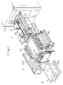
- an apparatus for trimming articles moldingly formed on a plastic sheet which comprises, a carriage having means for suckingly holding the molded article thereunder and means for reciprocally longitudinally moving the carriage through the apparatus, a first zone in which there is provided conveyor means for receiving said article from a forming machine to be brought under said carriage for suckingly holding, a second zone in which there are provided a pair of first cutter assemblies each comprising a longitudinal cutter device mounted on a base member; a pair of second cutter assemblies each comprising a transverse cutter device mounted on another base member; means for actuating said first assembly to transversely move between an inner position for trimming and a normal outer retreated position; means for actuating said second assembly to vertically move between an upper position for trimming and a normal lower retreated position, so that when said cutter assemblies are in the respective retreated positions the molded article is brought by said carriage in said zone, and then sequentially trimmed by the respective cutter devices moved to be in the respective trimming position according to said respectively concerned actuating means; means
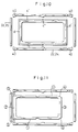
- the molded bath tub a has a cavity b defined by four side walls and a bottom wall, and is formed with outwardly protruded flanges from which side rims c , c′ as well as front and rear rims d , d′ are to be cut off.
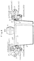
- said opposite side rims c , c′ are firstly and concurrently cut off by the pair of longitudinal cutter devices 20, 20′, and then the front rim d by the front cutter device 30 and finally the rear rim d′ by the rear cutter device 30′ as seen in Fig. 9.
- the molded article a such as the bath tub is exhausted out of a forming machine FM to be received by a carriage represented generally by 10 and now locating in a supplying zone I.
- the carriage 10 has a top plate 11 on which a reversible servomotor M1 and a nut member 12 are mounted which is driven by said motor M1 and engages with a longitudinally extended screw rod SR so that the carriage 10 may move to bring the article a together therewith to a trimming zone II and to an exhausting zone III, and then return back to said zone I.
- a pair of conveyor belts CB1 so as to support the article a exhausted out of the forming machine FM at the opposite side flanges ( c , c′ ) to be brought under the carriage 10. It is preferable to provide a pair of guide frames GF respectively extended along said conveyor belts CB.
- the conveyor belts CB1 are adapted to stop. Then, the article a is sucked to be held by the carriage 10 thereunder to be explained later in reference to Figs. 2 and 3.
- a trimming device in the zone II has a pair of longitudinal cutter devices 20, 20′, each of which is adapted to be transversely movable between an outer waiting position where the article a and the carriage 10 holding said article are allowed to enter therebetween without colliding therewith and an inner position for processing with longitudinal trimming, which is explained later in reference to Fig. 4, as well as a pair of transverse cutter device 30, 30′, each of which is adapted to be vertically movable between a lower waiting position where the article a held by the carriage 10 is allowed to move thereabove without colliding therewith and an upper position for proceeding with transverse trimming, which is explained later in reference to Fig. 5.
- transversely extended conveyor belt CB2 under the casing bottom wall for said four cutter devices 20, 20′, 30 and 30′ for exhausting rims of the plastic sheet on which the article a is formed, cut off by said cutter devices and falling down thereon.
- a further conveyor belt CB3 longitudinally extended so as to receive the article a from which unnecessary rims have been cut off and which is brought thereabove by the carriage 10 and falls down thereon to be exhausted out of the apparatus of the invention.
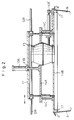
- the carriage top plate 11 engaging with said pair of guide rails GR so as to slindingly move therealong is further provided with a cylinder 13A of a hydraulic device fixed thereto, a piston 13B of which is fixed with an assembly at the free end thereof to be movable downwards and upwards. It is preferable to provide a pair of cylinder-piston guide members for the assembly to smoothly move vertically.
- the assembly comprises an upper plate member 14A, a lower plate member 14B and a pair of vertical members 14C respectively extending therebetween to form a frame.
- Said plate members 14A and 14B are respectively formed with holes for supporting a wind drum 15 therein which is open at upper and lower ends thereof and has a rotating fan 15′ therein so as to generate a back pressure thereunder.
- the distances between the pair of bars 16 and 16′ as well as the pair of bars 17 and 17′ are preferably made adjustable.
- one of said transverse bars, e.g. the rear bar 17′ is fixedly mounted not on said plate member 14B but on a separate plate member 14B′ which is slidingly movable relative thereto.
- the movable plate 14B′ may be moved e.g. by a reversible motor M2 and a nut-screw rod device as shown in Fig. 3.
- each of the longitudinal bars 16, 16′ may be provided with a plurality of pins respectively projected transversely inwards so as to be fitted in a plurality of grooves correspondingly formed in the plate member 14B at the side surface thereof and respectively fixed e.g. by nut-screw means.
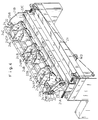
- the cutter device 20 is slindingly movable in the transverse direction as a whole on the machine frame bed according to a reversible motor M3 through sprocket wheels one of which is mounted on the output shaft of said motor, an endless sprocket chain extended around said sprocket wheels and a pair of screw rods respectively extended in the transverse direction, each on which each of the two of said wheels are fixedly mounted to be driven and a base plate 21 of said cutter device 20 is threadedly engaged for said transverse movement in either direction.
- a reversible motor M3 through sprocket wheels one of which is mounted on the output shaft of said motor, an endless sprocket chain extended around said sprocket wheels and a pair of screw rods respectively extended in the transverse direction, each on which each of the two of said wheels are fixedly mounted to be driven and a base plate 21 of said cutter device 20 is threadedly engaged for said transverse movement in either direction.
- Said base plate 21 is mounted with a pair of vertical end walls 21A, 21B, on either of which a reversible motor M4, a plurality of sprocket wheels one of which is fixedly mounted on the output shaft of said motor, and an endless sprocket chain extended therearound are provided.
- a stationary cutter assembly comprising a cutter blade holder 22 londitudinally extended between said end walls 21A, 21B on the inner side of the cutter device, similarly extended cutter blade 22′ which is fixed mounted thereon, and three pairs of arm levers 22A, 22B, 22C respectively fixed with said blade holder 22 at the respective inner side thereof.
- Said arm levers 22A, 22B, 22C have a longitudinally extended pivot rod 23 piercing therethrough at the respective outer side.
- an angularly movable cutter assembly comprising a longitudinally extended cutter blade holder 24, a cutter blade 24′ similarly extended and fixedly mounted thereon so as to oppositely face to said stationary blade 22′ thereabove to be engaged therewith for cutting the longitudinal rim off from the plastic sheet on which the article a is formed, and three pairs of similar arm levers 24A, 24B, 24C fixedly mounted on the side wall of said blade holder 24 at the respective inner side.
- Said arm levers 24A, 24B, 24C are mounted on said pivot rod 23 at the respective inner side thereof so as to be angularly movable thereon relative to said stationary cutter assembly comprising the blade holder 22, the blade 22′ and the arm levers 22A, 22B, 22C.
- Each pair of said movable arm levers 24A (24B, 24C) have an enlarged head of a piston 24AP (24BP, 24CP) of a hydraulic device therebetween and fixed therewith.
- a cylinder 22AS (22BS, 22CS) of said hydraulic device is fixed with said stationary arm lever 22A (22B, 22C) so that when the hydraulic device in the waiting position (see the left in Fig. 6) is actuated to retract the piston, the movable blade 24′ is engaged with the stationary blade 21′ (see the right in Fig. 6) so as to trim the article a .
- a larger assembly which comprises said stationary cutter assembly (blade holder 22, blade 22′, arm levers 22A, 22B, 22C, cylinders 22AS, 22BS, 22CS), said angularly movable cutter assembly (blade holder 24, blade 24′, arm levers 24A, 24B, 24C, pistons 24AP, 24BP, 24CP) and the pivot rod 23 on which said two assemblies are mounted so as to angularly movable with each other, is adapted to tilt as a whole relative to the base plate 21 and the opposite end walls 21A, 21B mounted thereon.
- a shaft 25A is fixed to the stationary arm lever 22A at one end, the other end of which is protruded out of the end wall 21A to be rotatable and mounted with one 25′ of the sprocket wheels referred to above.
- Another shaft 25B is fixed to the stationary arm lever 22C at one end, the other end of which is rotatably held by the other end wall 21B and mounted with the similar sprocket wheel (not seen in Fig. 4) which is drivingly engaged with another sprocket wheel (also not seen), which is mounted on a shaft 26 londitudinally extended between the end walls 21A, 21B, the other end of which is mounted with another sprocket wheel.
- the cutter device 20 or a further larger assembly comprising the base plate 21 and the opposite end walls 21A, 21B in addition to said larger assembly may be transversely moved, as a whole as referred to above, concurrently with the counter cutter device 20′.
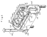
- the transversely extended cutter device 30 shown in Fig. 5 has a base member 31 and a pair of end walls 31A, 31B so as to form a frame, which is fixed to pistons 32A, 32B of a pair of hydraulic devices, of which cylinders 32A′ 32B′ fixed to the machine frame so that said frame 31, 31A, 31B may be vertically raised up and lowered down by actuating said hydraulic devices.
- a stationary cutter assembly comprising a cutter blade holder 33 transversely extended between said end walls 31A, 31B on the inner side of the cutter device, similarly extended cutter blade 33′ which is mounted thereon, and two pairs of arm levers 33A, 33B respectively fixed with said blade holder 33 at the respective inner side thereof.
- Said arm levers 33A, 33B have a transversely extended pivot rod 34 piercing therethrough at the respective outer side.
- an angularly movable cutter assembly comprising a transversely extended cutter blade holder 35, a cutter blade 35′ similarly extended and fixedly mounted thereon so as to oppositely face to said stationary blade 33′ thereabove to be engaged therewith for cutting the transverse rim off from the plastic sheet on which the article a is formed, and two pairs of similar arm levers 35A, 35B fixedly mounted on the side wall of said blade holder 35 at the respective inner side.
- Said movable arm levers 35A, 35B are mounted on said pivot rod 34 so as to be angularly movable thereon relative to said stationary cutter assembly.
- Each pair of said movable arm levers 35A (35B) have an enlarged had of piston 35AP (35BP) of a hydraulic device therebetween and fixed therewith.
- a cylinder 33AS (33BS) of said hydraulic device is fixed with said stationary arm lever 33A (33B) so that when the hydraulic device is actuated to retract the piston, the movable blade 35′ is engaged with the stationary blade 33′ so as to trim the article a .
- a larger assembly which comprises said stationary cutter assembly (blade holder 33, blade 33′, arm levers 33A, 33B, cylinder 33AS, 33BS) said angularly movable cutter assembly (blade holder 35, blade 35′, arm levers 35A, 35B, pistons 35AP, 35BP) and the pivot rod 34 on which said two assemblies are mounted so as to angularly movable with each other, is adapted to tilt as a whole relative to the base member 31 and the opposite end walls 31A, 31B mounted thereon, similar to the longitudinal cutter device referred to above in reference to Fig. 4.
- a shaft 36A is fixed to the stationary arm lever 33A at one end, the other end of which is protruded out of the end wall 31A to be rotatably and mounted with a sprocket wheel 36′ which is rotated by a reversible motor M5 through another sprocket wheel mounted on the output shaft of said motor and an endless sprocket chain extended therearound.
- Another shaft 36B is fixed to the stationary arm lever 33B, which is partly hidden by the neighbouring movable arm lever in Fig. 5, at one end, the other end of which is rotatably held by the opposite end wall 31B and mounted with a sprocket wheel (not seen in Fig.
- transverse cutter devices 30, 30′ are on the way of the carriage 10 holding the article a thereunder moving from the zone I to the zone II, and then from said zone II to the zone III, they can not move on the level where cutting is made to be in the waiting or retreated position like as the longitudinal cutter devices 20, 20′ and thus they are adapted to be lowered in the retreated position as explained above. And further since the article a held by the carriage thereunder is brought in the trimming position by placing the outwardly protruded flange portion thereof on the stationary blade of the cutter device, the movable blade of which is moved up to open the mouth thereof as shown in Fig.
- the front and rear transverse trimming can not be concurrently done different from the left and right longitudinal trimming so that the front trimming is secondly made by the front transverse cutter device 30 and the rear trimming is finally made by the rear transverse cutter device 30′ as referred to above and shown in Fig. 9.
- the longitudinal cutter blades 22′, 24′ When it is necessary to make a particular longitudinal trimming c′ or corner trimming c ⁇ as shown in Figs. 10 and 11, the longitudinal cutter blades 22′, 24′ must be replaced with correspondingly shaped ones and four pairs of blades 40 must be provided separate from the longitudinal cutter blades (22′, 24′).
- the corner trimming is preferably made fourthly at the rear corners after the third rear transverse trimmingly and then fifthly at the front corners.
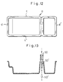
- molded article a such as the linings for the smaller compartment for ice making or freezing and the larger compartment for cold storage of the refrigerator are combinedly formed and must be separated
- an upper blade 50 or pair of blades at the lower plate 14B of the carriage 10 to be vertically movable and a lower blade 50′ in the zone II also to be vertically movable so as to separate the two portions by engaging said upper and lower blades 50, 50′.
- the pair of conveyor belts CB1 are actuated to run so as to convey the article a with holding transversely outwards protruded flange portions thereof just below the carriage 10 now located in the zone I.
- the conveyor belts CB1 are adapted to stop and the piston 13B of the hydraulic device is adapted to move downwards so that the two pairs of bars 16, 16', 17, 17' mounted under the sucking frame 14A, 14B, 14C of the carriage fit in the article cavity b and concurrently the fan 15' in the wind drum 15 is driven to rotate so that the article a is suckingly held by the carriage thereunder.
- the motor M1 is designed to be driven in one direction so that the carriage 10 moves together with the article a towards the zone II owing to thread engagement of the nut member 12 with the longitudinally extended screw rod SR.
- the motor M1 is adapted to stop and the motor M3 is driven to transversely move the longitudinal cutter devicess 20, 20' towards the article a so that the concerned stationary blade 22' is positioned relative to the outwardly protruded flange portion c or the article a (see the left in Fig. 6), for which the motor M4 is actuated so as to tilt the cutter assembly comprising the stationary blade 22' a little.
- the pistons 24AP, 24BP, 24CP are retracted in the respective cylinders so as to proceed with longitudinal trimming of the article at the both sides, after which the motor M3 is adapted to drive in the other direction so as to move the both cutter devices 20, 20′ apart from the article, and then or during which the motor M4 is energized to tilt the cutter assembly by an angle of about 90° to be in the position shown in Fig. 7 for releasing the cut off rim e to fall down when actuating the pistons 24AP, 24BP, 24CP to protrude more.
- the front transverse cutter device 30 is moved upwards by protruding pistons 32A, 32B more out of the concerned cylinders with keeping the movable blade 35′ disengaged from the stationary blade 33′ to be in the level for trimming, and then the carriage 10 is moved a little forward so that the forwardly protruded flange portion d of the article is inserted in the open mouth formed between the blades 33′ and 35′, after which the motor M5 is driven a little so that article flange d is placed on the stationary blade 33′.
- the pistons 35AP, 35BP are retracted in the respective cylinders to cut off the rim d from the article similar to the above.
- the transverse cutter devices 30, 30′ are retreated in the lower position and cut rim release is made by driving the motor M5 so as to rotate the shafts 36A, 36B for tilting the stationary and movable cutter assembly similar to the above.
- the carriage 10 is moved to be in the zone III where the fan 15' is stopped so that the trimmed article a falls down owing to the gravity on the belt CB3.
- the motor M1 is energized to rotate the nut member 12 in the other direction so that the carriage is returned to the initial position in the zone I for repeating the above operations.
- the wind drum provided with the fan may be replaced e.g. with a vacuum pump.
- the sprocket wheels-sprocket chain may be replaced e.g. with pulleys-belt or string, gearings etc.
- the number of arm lever pairs in the cutter device is not critical. For instance, three, four or five pairs may be used instead of two or three pairs in the illustrated embodiment. Furthermore one or two pairs may be used instead of two or three pairs so far as power of the hydraulic or pneumatic cylinder-piston device is sufficient for cutting and any suitable means is provided for stable movement and balanced power along the length thereof.
Landscapes
- Engineering & Computer Science (AREA)
- Mechanical Engineering (AREA)
- Life Sciences & Earth Sciences (AREA)
- Forests & Forestry (AREA)
- Physics & Mathematics (AREA)
- Fluid Mechanics (AREA)
- Processing And Handling Of Plastics And Other Materials For Molding In General (AREA)
- Perforating, Stamping-Out Or Severing By Means Other Than Cutting (AREA)
- Blow-Moulding Or Thermoforming Of Plastics Or The Like (AREA)
Claims (8)
- Appareil d'ébavurage d'articles (a) formés par moulage d'une feuille du motière plastique, qui comprend
un chariot (10) comprenant un dispositif (15, 15') de maintien par aspiration de l'article moulé (a) placé au-dessous de lui, et un dispositif (M1, 12, SR) destiné à déplacer longitudinalement en translation le chariot (10) dans l'appareil,
une première zone (I) dans laquelle est placé un dispositif transporteur (CB1) destiné à recevoir l'article d'une machine de mise en forme (FM) afin qu'il soit transporté sous le chariot (10) qui assure son maintien par aspiration,
une seconde zone (II) dans laquelle sont placés deux premiers ensembles à organes de coupe, comprenant chacun un dispositif à organe longitudinal de coupe (20, 20') monté sur un organe de base (21), une paire de seconds ensembles à organes de coupe, comprenant chacun un dispositif à organe de coupe transversal (30, 30') monté sur un autre organe de base (31), un dispositif (M3) de manoeuvre du premier ensemble afin qu'il se déplace transversalement entre une position interne d'ébavurage et une position externe normale reculée, un dispositif (32A, 32B) de manoeuvre du second ensemble afin qu'il le déplace verticalement entre une position supérieure d'ébavurage et une position inférieure normale reculée, si bien que, lorsque les ensembles à organe de coupe sont dans les positions reculées respectives, l'article moulé (a) est placé par le chariot (10) dans ladite zone (II), puis est ébavuré successivement par les dispositifs respectifs à organes de coupe (20, 20', 30, 30') qui sont déplacés dans leur position respective d'ébavurage sous la commande du dispositif de manoeuvre concerné, un dispositif (M4, M5) destiné à faire basculer les dispositifs à organes de coupe longitudinaux et transversaux (20, 20', 30, 30') d'un angle d'environ 90° par rapport à l'organe respectif de base (21, 31) afin que les parties longitudinales ébavurées de feuille de matière plastique soient libérées et tombent, et un dispositif transporteur (CB2) disposé transversalement afin qu'il évacue les parties de feuille ébavurée provenant de l'appareil, et
une troisième zone (III) qui comporte un dispositif placé longitudinalement afin qu'il évacue l'article moulé ébavuré (a), placé au-dessus de lui et libéré par le chariot (10) afin qu'il tombe sur lui, vers l'extérieur de l'appareil. - Appareil selon la revendication 1, dans lequel le dispositif destiné à déplacer en translation le chariot (10) comprend une tige filetée (SR) montée sur un châssis de machine et destinée à être placée longitudinalement dans les trois zones (I, II, III) et un moteur réversible (M1) et un organe à écrou (12) entraîné par celui-ci afin qu'il tourne, montés sur le chariot (10) afin que l'organe à écrou (12) coopère par vissage avec la tige filetée (SR).
- Appareil selon la revendication 2, dans lequel le dispositif de maintien par aspiration comprend un organe (11) ayant une plaque supérieure, un organe (14A, 14B, 14C) ayant un cadre inférieur et un dispositif à cylindre et piston (13A, 13B) raccordant les deux organes (11, 14A, 14B, 14C) de manière que le dernier organe (14A, 14B, 14C) puisse être abaissé et soulevé par rapport au premier (11), l'organe de cadre (14A, 14B, 14C) étant destiné à s'ajuster intimement dans l'article moulé et ayant un dispositif d'aspiration (15, 15') si bien que, lors de la descente de l'organe de cadre afin qu'il s'ajuste dans l'article moulé et de la commande du dispositif d'aspiration (15, 15'), l'article peut être supporté par le chariot (10) alors que, lorsque le dispositif d'aspiration (15, 15') est désactivé, l'article peut être libéré et peut tomber.
- Appareil selon la revendication 1, dans lequel le dispositif à organes de coupe (20, 20') comporte deux organes allongés de coupe (22', 24') ayant chacun plusieurs bras de leviers (22A, 24A, 22B, 24B, 22C, 24C) qui leur sont fixés, une tige (23) de pivotement allongée de manière analogue et disposée dons les bras de leviers parallèlement aux organes allongés de coupe (22', 24') afin qu'un premier jeu (24', 24A, 24B, 24C) d'organes de coupe et de leviers soit mobile angulairement par rapport à l'autre jeu (22', 22A, 22B, 22C) qui est retenu par l'organe allongé de base (21) entre les parois opposées d'extrémité (21A, 21B) de celui-ci, et un dispositif à cylindre et piston (22AS, 22BS, 22CS, 24AP, 24BP, 24CP) raccordant les deux ensembles de manière que, lors de la commanda du dispositif, le jeu mobile angulairement, normalement en position dégagée, puisse venir coopérer avec l'outre jeu pour l'ébavurage.
- Appareil selon la revendication 1, dans lequel le dispositif de manoeuvre du premier ensemble afin qu'il se déplace transversalement comprend un moteur réversible (M3) monté sur un châssis de machine et un dispositif à vis et écrou dont l'un est monté sur l'ensemble alors que l'autre est destiné à être entrainé par le moteur (M3) afin que, lorsque le moteur est alimenté afin qu'il tourne dans un sens ou dans l'autre, l'ensemble puisse se déplacer par coulissement sur le châssis de machine et qu'il prenne l'une ou l'autre des deux positions.
- Appareil selon la revendication 1, dans lequel le dispositif de manoeuvre du second ensemble à organes de coupe destiné à le déplacer verticalement comprend un dispositif à cylindre et piston (32A, 32A', 32B, 32B') dont l'un est monté sur l'ensemble et l'autre est monté sur un châssis de manière que, lorsque le dispositif est commandé, l'ensemble puisse se déplacer verticalement par rapport au châssis de la machine.
- Appareil selon la revendication 4, dans lequel le dispositif destiné à faire basculer le dispositif à organe de coupe par rapport à l'organe de base (21, 31) comporte un moteur réversible (M4, M5) et une paire d'arbres (25A, 25B, 35A, 35B) ayant chacun une première extrémité fixée aux leviers fixes externes (22A, 22C, 34A, 34C) alors que l'autre extrémité de l'arbre est supportée par la paroi d'extrémité (21A, 21B, 31A, 31B) qui est concernée afin que, lorsque le moteur (M4, M5) est entrainé dans un sens ou dans l'autre, les arbres (25A, 25B, 35A, 35B) puissent tourner et en conséquence les organes de coupe fixes et mobiles angulairement puissent basculer comme un tout pour la libération des parties ébavurées de feuille de matière plastique qui peuvent alors tomber.
- Procédé de mise en oeuvre de l'appareil selon la revendication 1, comprenant les étapes suivantes :
la commande du dispositif transporteur (CBI) afin qu'il reçoive l'article moulé (a) destiné à être placé sous le chariot (10) occupant la première zone (I),
l'abaissement et la commande du dispositif d'aspiration (15, 15') afin que l'article (a) placé au-dessous soit retenu,
la commande du dispositif de déplacement (CBI) afin que le chariot (10) supportant l'article (a) soit déplacé vers l'avant et se trouve dans la seconde zone (II),
la commande du dispositif (M3) de manoeuvre de manière que la paire de premiers ensembles à organes de coupe soit mise simultanément en position respective d'ébavurage dans laquelle les dispositifs à organes de coupe (20, 20') sont commandés simultanément pour l'ébavurage longitudinal de l'article moulé (a) supporté par le chariot (10), et la paire des premiers ensembles à organes de coupe est ensuite ramenée simultanément en arrière en position respective reculée, dans laquelle le dispositif de basculement (M4) est commandé afin qu'il libère les parties longitudinales ébavurées de feuille de matière plastique, puis
le déplacement du chariot (10) portant l'article (a) un peu en avant afin que la partie concernée de l'article (a) puisse coopérer avec le dispositif transversal avant de coupe (30) du second ensemble à organe de coupe qui est alors soulevé en position d'ébavurage dans laquelle le dispositif (30) à organe de coupe est commandé pour l'ébavurage transversal avant, puis
le déplacement du chariot (10) un peu vers l'arrière de manière que la partie concernée de l'article (a) ainsi maintenue puisse coopérer avec le dispositif transversal arrière de coupe (30') du second ensemble à organe de coupe qui est maintenant levé en position d'ébavurage dans laquelle le dispositif (30') à organe de coupe est commandé afin qu'il assure l'ébavurage transversal arrière, et les deux ensembles à organe de coupe sont ensuite abaissés afin qu'ils prennent leur position respective reculée, et le dispositif (M5) de basculement concerné est commandé respectivement afin que les parties transversales ébavurées de la feuille de matière plastique soient libérées, avec pendant ce temps
commande du dispositif transporteur (CB2) dans la seconde zone de manière que les parties ébavurées de feuille de matière plastique tombent sur ce dispositif soient évacuées de l'appareil,
le déplacement du chariot (10) vers l'avant afin qu'il se trouve dans la troisième zone (III) dans laquelle le dispositif d'aspiration (15, 15') est désactivé afin que l'article ébavuré (a) tombe sur le dispositif transporteur (CB3) et soit évacué de l'appareil, et
le déplacement du chariot (10) afin qu'il revienne dans la première zone (I) pour la répétition de ces étapes.
Applications Claiming Priority (2)
| Application Number | Priority Date | Filing Date | Title |
|---|---|---|---|
| JP11576/88 | 1988-01-21 | ||
| JP63011576A JPH0616997B2 (ja) | 1988-01-21 | 1988-01-21 | 樹脂成形物の切断装置及び切断方法 |
Publications (3)
| Publication Number | Publication Date |
|---|---|
| EP0325036A2 EP0325036A2 (fr) | 1989-07-26 |
| EP0325036A3 EP0325036A3 (fr) | 1991-04-24 |
| EP0325036B1 true EP0325036B1 (fr) | 1994-04-06 |
Family
ID=11781740
Family Applications (1)
| Application Number | Title | Priority Date | Filing Date |
|---|---|---|---|
| EP88311234A Expired - Lifetime EP0325036B1 (fr) | 1988-01-21 | 1988-11-28 | Dispositif pour le découpage d'articles moulés dans une feuille en matière thermoplastique et procédé pour son fonctionnement |
Country Status (4)
| Country | Link |
|---|---|
| US (1) | US4991479A (fr) |
| EP (1) | EP0325036B1 (fr) |
| JP (1) | JPH0616997B2 (fr) |
| DE (1) | DE3888957T2 (fr) |
Families Citing this family (11)
| Publication number | Priority date | Publication date | Assignee | Title |
|---|---|---|---|---|
| DE4406057C2 (de) * | 1994-02-24 | 1996-06-05 | Georg Geis Maschinenfabrik | Anlage zur Herstellung und Fertigbearbeitung von Kunststoff-Formteilen |
| UA28711A (uk) * | 1997-09-01 | 2000-10-16 | Товариство З Обмеженою Відповідальністю "Ліком Лтд" | Машина пневмоформувальна |
| US6382064B1 (en) * | 1999-11-12 | 2002-05-07 | Modern Technologies & Machinery, Inc. | Apparatus and method for trimming formed elements |
| FR2806658B1 (fr) * | 2000-03-22 | 2002-08-02 | Visteon Systemes Interieurs | Procede et dispositif de realisation d'un contour d'une piece planiforme, notamment destinee a l'equipement interieur de vehicule automobile |
| US7475619B2 (en) * | 2005-04-22 | 2009-01-13 | The Stanley Works | Over torque proof socket |
| DE102005022004A1 (de) * | 2005-05-09 | 2006-11-16 | Geiss Ag | Vorrichtung zur Bearbeitung einer umgeformten Thermoplastplatte |
| CN104760175A (zh) * | 2015-03-27 | 2015-07-08 | 安徽信盟机电装备制造有限公司 | 一种新型的冰箱内胆修边设备 |
| US10639810B2 (en) | 2016-11-17 | 2020-05-05 | Milan Conception Inc. | Method and cutting apparatus for cutting blank profiles |
| CN112917536B (zh) * | 2021-02-04 | 2023-04-11 | 成都精钟满机械设备制造有限公司 | 一种笋子切花机 |
| CN114589243B (zh) * | 2022-03-04 | 2023-07-25 | 广州市晟阳金属制品有限公司 | 一种新型冲裁接刀工艺 |
| CN120886336B (zh) * | 2025-09-30 | 2025-12-12 | 温州高格机械科技有限公司 | 西林瓶装盒自动生产设备 |
Family Cites Families (10)
| Publication number | Priority date | Publication date | Assignee | Title |
|---|---|---|---|---|
| US3461761A (en) * | 1967-04-20 | 1969-08-19 | Mojonnier Inc Albert | Apparatus for trimming plastic preforms |
| DE2251768A1 (de) * | 1972-10-21 | 1974-05-02 | Nordischer Maschinenbau | Thermoformmaschine |
| US3968714A (en) * | 1974-01-11 | 1976-07-13 | Charles Kuchyt | Heavy duty shear |
| US4175897A (en) * | 1978-01-05 | 1979-11-27 | Golomovzjuk Ivan K | Apparatus for removing flash from resistance butt-weld joints in rails |
| DE3034621A1 (de) * | 1980-09-13 | 1982-05-06 | Aristo Graphic Systeme Gmbh & Co Kg, 2000 Hamburg | Verfahren und schneidvorrichtung zur herstellung von zuschnitten |
| DE3128680C2 (de) * | 1981-07-21 | 1983-12-01 | Adolf Illig Maschinenbau Gmbh & Co, 7100 Heilbronn | Längs- und Querschneidevorrichtung |
| DE3302946C2 (de) * | 1982-02-05 | 1986-12-04 | H. Wohlenberg KG GmbH & Co, 3000 Hannover | Drei-Messer-Schneidemaschine |
| US4434691A (en) * | 1982-04-12 | 1984-03-06 | Gerber Garment Technology, Inc. | Method and apparatus for sealing cut sheet material |
| JPS60135197A (ja) * | 1983-12-23 | 1985-07-18 | 株式会社浅野研究所 | 樹脂成形物の直線トリミング装置 |
| JPS6157461A (ja) * | 1984-08-22 | 1986-03-24 | Asano Kenkyusho:Kk | シ−ト成形物の直線トリミング装置におけるシ−ト挟着装置 |
-
1988
- 1988-01-21 JP JP63011576A patent/JPH0616997B2/ja not_active Expired - Lifetime
- 1988-11-28 DE DE3888957T patent/DE3888957T2/de not_active Expired - Fee Related
- 1988-11-28 EP EP88311234A patent/EP0325036B1/fr not_active Expired - Lifetime
- 1988-12-27 US US07/290,340 patent/US4991479A/en not_active Expired - Fee Related
Also Published As
| Publication number | Publication date |
|---|---|
| DE3888957T2 (de) | 1994-11-03 |
| JPH01188295A (ja) | 1989-07-27 |
| DE3888957D1 (de) | 1994-05-11 |
| EP0325036A2 (fr) | 1989-07-26 |
| JPH0616997B2 (ja) | 1994-03-09 |
| US4991479A (en) | 1991-02-12 |
| EP0325036A3 (fr) | 1991-04-24 |
Similar Documents
| Publication | Publication Date | Title |
|---|---|---|
| EP0325036B1 (fr) | Dispositif pour le découpage d'articles moulés dans une feuille en matière thermoplastique et procédé pour son fonctionnement | |
| US8181432B2 (en) | Web packaging system with ergonomic forming plug change | |
| US7607279B2 (en) | Web packaging system with ergonomic tooling change | |
| US7886645B2 (en) | Exact weight cutting and destacking system for food products | |
| US3451192A (en) | Bread bagger | |
| GB2280869A (en) | Forming portions of foodstuffs | |
| US20060196328A1 (en) | Loaf seam synchronization device for continuous loaf feed slicing machine | |
| US4583436A (en) | Apparatus for trimming articles moldingly formed on plastic sheet | |
| US4553464A (en) | Size trimmer | |
| EP0515661B1 (fr) | Procede et machine d'emballage a mouvement d'indexation servomotorisee | |
| US3998252A (en) | Wood slicing apparatus | |
| CN221456025U (zh) | 一种火锅底料分切机构 | |
| US3260297A (en) | Apparatus for removing the squeeze-out on rubber tires | |
| US3738787A (en) | Apparatus for severing articles from a continuous thermoplastic web molded on rotary vacuum forming machines | |
| KR20220066543A (ko) | 골절기를 이용한 냉동식품 절단장치 | |
| JPH0160399B2 (fr) | ||
| GB1453939A (en) | Packaging and cutting apparatus | |
| JPH10156622A (ja) | 長尺材を設定した寸法に切断する装置 | |
| JPH09300287A (ja) | スライサ | |
| CN223541289U (zh) | 一种自动翻转上料机构及其高速切肉机 | |
| CN222115868U (zh) | 一种具有切边功能的注塑模具 | |
| JPH0227922B2 (fr) | ||
| US2726718A (en) | Apparatus for cutting blanks from sheet material | |
| CN218172826U (zh) | 一种自动切边立式封口机 | |
| CN213471972U (zh) | 定子自动塑封系统 |
Legal Events
| Date | Code | Title | Description |
|---|---|---|---|
| PUAI | Public reference made under article 153(3) epc to a published international application that has entered the european phase |
Free format text: ORIGINAL CODE: 0009012 |
|
| AK | Designated contracting states |
Kind code of ref document: A2 Designated state(s): DE FR GB IT |
|
| PUAL | Search report despatched |
Free format text: ORIGINAL CODE: 0009013 |
|
| AK | Designated contracting states |
Kind code of ref document: A3 Designated state(s): DE FR GB IT |
|
| 17P | Request for examination filed |
Effective date: 19910529 |
|
| 17Q | First examination report despatched |
Effective date: 19920622 |
|
| GRAA | (expected) grant |
Free format text: ORIGINAL CODE: 0009210 |
|
| AK | Designated contracting states |
Kind code of ref document: B1 Designated state(s): DE FR GB IT |
|
| ITF | It: translation for a ep patent filed | ||
| REF | Corresponds to: |
Ref document number: 3888957 Country of ref document: DE Date of ref document: 19940511 |
|
| ET | Fr: translation filed | ||
| PLBE | No opposition filed within time limit |
Free format text: ORIGINAL CODE: 0009261 |
|
| STAA | Information on the status of an ep patent application or granted ep patent |
Free format text: STATUS: NO OPPOSITION FILED WITHIN TIME LIMIT |
|
| 26N | No opposition filed | ||
| REG | Reference to a national code |
Ref country code: GB Ref legal event code: IF02 |
|
| PGFP | Annual fee paid to national office [announced via postgrant information from national office to epo] |
Ref country code: GB Payment date: 20021029 Year of fee payment: 15 |
|
| PGFP | Annual fee paid to national office [announced via postgrant information from national office to epo] |
Ref country code: FR Payment date: 20021114 Year of fee payment: 15 |
|
| PGFP | Annual fee paid to national office [announced via postgrant information from national office to epo] |
Ref country code: DE Payment date: 20021119 Year of fee payment: 15 |
|
| PG25 | Lapsed in a contracting state [announced via postgrant information from national office to epo] |
Ref country code: GB Free format text: LAPSE BECAUSE OF NON-PAYMENT OF DUE FEES Effective date: 20031128 |
|
| PG25 | Lapsed in a contracting state [announced via postgrant information from national office to epo] |
Ref country code: DE Free format text: LAPSE BECAUSE OF NON-PAYMENT OF DUE FEES Effective date: 20040602 |
|
| GBPC | Gb: european patent ceased through non-payment of renewal fee |
Effective date: 20031128 |
|
| PG25 | Lapsed in a contracting state [announced via postgrant information from national office to epo] |
Ref country code: FR Free format text: LAPSE BECAUSE OF NON-PAYMENT OF DUE FEES Effective date: 20040730 |
|
| REG | Reference to a national code |
Ref country code: FR Ref legal event code: ST |
|
| PG25 | Lapsed in a contracting state [announced via postgrant information from national office to epo] |
Ref country code: IT Free format text: LAPSE BECAUSE OF NON-PAYMENT OF DUE FEES;WARNING: LAPSES OF ITALIAN PATENTS WITH EFFECTIVE DATE BEFORE 2007 MAY HAVE OCCURRED AT ANY TIME BEFORE 2007. THE CORRECT EFFECTIVE DATE MAY BE DIFFERENT FROM THE ONE RECORDED. Effective date: 20051128 |