EP0325082B1 - Mécanisme à recirculation de billes - Google Patents
Mécanisme à recirculation de billes Download PDFInfo
- Publication number
- EP0325082B1 EP0325082B1 EP88500003A EP88500003A EP0325082B1 EP 0325082 B1 EP0325082 B1 EP 0325082B1 EP 88500003 A EP88500003 A EP 88500003A EP 88500003 A EP88500003 A EP 88500003A EP 0325082 B1 EP0325082 B1 EP 0325082B1
- Authority
- EP
- European Patent Office
- Prior art keywords
- actuator shaft
- output piston
- balls
- thread
- base line
- Prior art date
- Legal status (The legal status is an assumption and is not a legal conclusion. Google has not performed a legal analysis and makes no representation as to the accuracy of the status listed.)
- Expired - Lifetime
Links
- 230000003134 recirculating effect Effects 0.000 title claims description 13
- 238000006073 displacement reaction Methods 0.000 claims description 3
- 230000000712 assembly Effects 0.000 description 1
- 238000000429 assembly Methods 0.000 description 1
- 230000015572 biosynthetic process Effects 0.000 description 1
- 239000002131 composite material Substances 0.000 description 1
- 150000001875 compounds Chemical class 0.000 description 1
- 238000010276 construction Methods 0.000 description 1
- 230000001788 irregular Effects 0.000 description 1
- 238000004519 manufacturing process Methods 0.000 description 1
- 230000007704 transition Effects 0.000 description 1
Images
Classifications
-
- B—PERFORMING OPERATIONS; TRANSPORTING
- B62—LAND VEHICLES FOR TRAVELLING OTHERWISE THAN ON RAILS
- B62D—MOTOR VEHICLES; TRAILERS
- B62D3/00—Steering gears
- B62D3/02—Steering gears mechanical
- B62D3/04—Steering gears mechanical of worm type
- B62D3/06—Steering gears mechanical of worm type with screw and nut
- B62D3/08—Steering gears mechanical of worm type with screw and nut using intermediate balls or the like
-
- F—MECHANICAL ENGINEERING; LIGHTING; HEATING; WEAPONS; BLASTING
- F16—ENGINEERING ELEMENTS AND UNITS; GENERAL MEASURES FOR PRODUCING AND MAINTAINING EFFECTIVE FUNCTIONING OF MACHINES OR INSTALLATIONS; THERMAL INSULATION IN GENERAL
- F16H—GEARING
- F16H25/00—Gearings comprising primarily only cams, cam-followers and screw-and-nut mechanisms
- F16H25/18—Gearings comprising primarily only cams, cam-followers and screw-and-nut mechanisms for conveying or interconverting oscillating or reciprocating motions
- F16H25/20—Screw mechanisms
- F16H25/22—Screw mechanisms with balls, rollers, or similar members between the co-operating parts; Elements essential to the use of such members
- F16H25/2204—Screw mechanisms with balls, rollers, or similar members between the co-operating parts; Elements essential to the use of such members with balls
- F16H25/2214—Screw mechanisms with balls, rollers, or similar members between the co-operating parts; Elements essential to the use of such members with balls with elements for guiding the circulating balls
- F16H25/2228—Screw mechanisms with balls, rollers, or similar members between the co-operating parts; Elements essential to the use of such members with balls with elements for guiding the circulating balls the device for circulation forming a part of the screw member
-
- Y—GENERAL TAGGING OF NEW TECHNOLOGICAL DEVELOPMENTS; GENERAL TAGGING OF CROSS-SECTIONAL TECHNOLOGIES SPANNING OVER SEVERAL SECTIONS OF THE IPC; TECHNICAL SUBJECTS COVERED BY FORMER USPC CROSS-REFERENCE ART COLLECTIONS [XRACs] AND DIGESTS
- Y10—TECHNICAL SUBJECTS COVERED BY FORMER USPC
- Y10T—TECHNICAL SUBJECTS COVERED BY FORMER US CLASSIFICATION
- Y10T74/00—Machine element or mechanism
- Y10T74/19—Gearing
- Y10T74/19642—Directly cooperating gears
- Y10T74/19698—Spiral
- Y10T74/19702—Screw and nut
- Y10T74/19744—Rolling element engaging thread
- Y10T74/19749—Recirculating rolling elements
- Y10T74/19753—Plural independent recirculating element paths
Definitions
- the present invention relates to a recirculating ball mechanism and, more particularly, but not exclusively, to a recirculating ball steering mechanism for automotive vehicles.
- such a steering assembly comprises an actuator shaft adapted to be rotatably driven by the steering wheel of a vehicle and formed with a screw thread.
- the actuator shaft is received inside a slideably mounted output piston and operably connected thereto by a series of balls located in the screw thread of the actuator shaft and in a corresponding screw thread on an inner surface of the output piston. Rotation of the actuator shaft causes the balls to progress along the thread and means are therefore provided to recirculate the balls to their point of origin.
- a recirculating ball mechanism comprising a body, an actuator shaft rotatably mounted within the body and turnable in response to rotation of an input shaft, an output piston slideably mounted in the body, a bore within the output piston in which is received an end of the actuator shaft, the bore having an internal threaded surface, the end of the actuator shaft being formed with a threaded surface, a series of balls located between the two threaded surfaces so as to operatively connect the actuator shaft to the output piston whereby a given rotation of the actuator shaft produces an associated displacement of the output piston in the body, and means for recirculating the balls to a point of origin in the thread formed on the actuator shaft, the thread comprising at least one closed loop the base line of which being defined as the path taken by the center of a ball relative to the longitudinal axis of actuator shaft after a complete rotation around the circumference of the actuator shaft, the closed loop including a first part of part helical form corresponding to the thread of the output piston, and a second part including a region whose
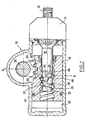
- a recirculating ball mechanism which, in the example shown is a steering assembly, comprises a body 10 in which is rotatably mounted an input shaft 12 destined to be connected to the steering column of a vehicle (not shown).
- the input shaft 12 is connected to a power steering valve assembly which is located at an end of the body 10 in a region shown by reference numeral 14.
- An actuator shaft 16 is operably connected to the input shaft 12 and projects into the interior of the body 10.
- An output piston 18 is slideably mounted in a bore 20 formed in the body 10 and receives the actuator shaft 16 in a longitudinally extending bore 22.
- the internal surface of the bore 22 in the output piston 18 is formed with a continuous helical thread 24.
- the distal end 26 of the actuator shaft 16 is of reduced diameter and is formed with a screw thread 28 which will be described in greater detail below.
- a series of balls 30 are located in the interstices between the two screw threads 24 and 28 and serve to operatively connect the actuator shaft 16 to the output piston 18 in such a way that rotation of the actuator shaft 16 in a given direction will produce a corresponding displacement of the output piston 18 in the bore 20.
- the outer surface of the output piston 18 has a number of gear teeth 32 defined therein which are adapted to mesh with corresponding teeth 34 formed on an output shaft 36.
- the output shaft 36 is rotatably mounted in the body 10 by means of two roller bearings 38.
- the screw thread 28 includes means to recycle the balls 30 so as to allow a continuous movement of the output piston 18 relative to the actuator shaft 16.
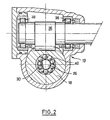
- the screw thread 28 comprises a number, two in the illustrated example, of separate closed loops 40 which extend around the circumference of the end 26 of the actuator shaft 16. As shown in Figure 2, each loop 40 contains a contiguous series of balls 30.
- Each loop 40 comprises a first part 42, corresponding approximately to half the circumference of the end 26 of the actuator shaft 16, which is of part-helical form and which corresponds to the shape of the thread 24 formed in the output piston 18.
- a second part 44 of the thread 28 completes the loop 40.
- the second part 44 has a generally Z-shape.
- the radial depth of the second part 44 is greater than that of the first part 42 or that of the thread 24.
- the radial depth of the second part 44 is approximately equivalent to the diameter of one of the balls 30 so that the ball 30 may pass under the projecting part 46.
- the two loops 40 are formed in the actuator shaft 16 in such a way that the respective second parts 44 are arranged at approximately 180 ° to each other so as to more evenly distribute the load on the output piston 18.
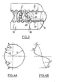
- the precise form of the thread 28 will now be described with reference to the curves shown in Figures 4a and 4b.
- the base line shown in Figures 4a and 4b is defined as the path taken by the centre of a given ball 30 relative to the longitudinal axis of the actuator shaft 16, starting and finishing at the same given point after a complete rotation around the circumference of the shaft 16.
- the base line forms a closed, compound, irregular figure which may nominally be divided into the following sections.
- connection areas, A -4 B and C - D in Figure 4a These parts of the curve correspond, respectively to the entry of a ball into, and its exit from, the second part 44 of the loop 40.
- the base line in these parts of the curve corresponds to a helical line with constant feed for the full portion of rotation, but with a variable radius.
- the projection of these parts of the base line on to a sloping plane tangential to the base helix produces two symmetrical arcs relative to the transverse axis of symmetry of the end 26 of the actuator shaft 16.
- the inflection area, B - 4 C in Figure 4a In this area the balls 40 move from one end to the other of the connection area, thus completing their path around the longitudinal axis of the actuator shaft 16.
- the base line in this portion is obtained by the succession of points situated at a constant distance from the longitudinal axis of the actuator shaft 16, with variable feed. This feed may be determined by a sine function or by the connection of two radii and the sign is negative relative to the feed of the base helix of the embracement area.
- Figure 4B is a projection of Figure 4A in axial form and points A,B,C,D of Figures 4A thus correlate to points A',B',C',D' of figure 4B.
- the construction of the assembly is simplified with respect to previously proposed assemblies. It is envisaged that, in order to further reduce costs, the loop may be cut by numerically controlled machines or by formation by microfusion.
Landscapes
- Engineering & Computer Science (AREA)
- Mechanical Engineering (AREA)
- General Engineering & Computer Science (AREA)
- Chemical & Material Sciences (AREA)
- Combustion & Propulsion (AREA)
- Transportation (AREA)
- Transmission Devices (AREA)
Claims (5)
Priority Applications (4)
| Application Number | Priority Date | Filing Date | Title |
|---|---|---|---|
| DE8888500003T DE3861190D1 (de) | 1988-01-18 | 1988-01-18 | Kugelumlaufmechanismus. |
| ES88500003T ES2018885B3 (es) | 1988-01-18 | 1988-01-18 | Mecanismo de recirculacion de bolas. |
| EP88500003A EP0325082B1 (fr) | 1988-01-18 | 1988-01-18 | Mécanisme à recirculation de billes |
| US07/297,895 US4924722A (en) | 1988-01-18 | 1989-01-17 | Recirculating ball mechanism |
Applications Claiming Priority (1)
| Application Number | Priority Date | Filing Date | Title |
|---|---|---|---|
| EP88500003A EP0325082B1 (fr) | 1988-01-18 | 1988-01-18 | Mécanisme à recirculation de billes |
Publications (2)
| Publication Number | Publication Date |
|---|---|
| EP0325082A1 EP0325082A1 (fr) | 1989-07-26 |
| EP0325082B1 true EP0325082B1 (fr) | 1990-11-28 |
Family
ID=8200510
Family Applications (1)
| Application Number | Title | Priority Date | Filing Date |
|---|---|---|---|
| EP88500003A Expired - Lifetime EP0325082B1 (fr) | 1988-01-18 | 1988-01-18 | Mécanisme à recirculation de billes |
Country Status (4)
| Country | Link |
|---|---|
| US (1) | US4924722A (fr) |
| EP (1) | EP0325082B1 (fr) |
| DE (1) | DE3861190D1 (fr) |
| ES (1) | ES2018885B3 (fr) |
Families Citing this family (15)
| Publication number | Priority date | Publication date | Assignee | Title |
|---|---|---|---|---|
| US5388475A (en) * | 1993-09-15 | 1995-02-14 | Beaver Precision Products | Ball nut and method of manufacturing same |
| US5993174A (en) * | 1994-08-23 | 1999-11-30 | Nikkiso Co., Ltd. | Pulsation free pump |
| US6192585B1 (en) * | 1998-11-04 | 2001-02-27 | Valeo Electrical Systems, Inc. | Ball nut and method of high volume manufacturing of same |
| JP3844922B2 (ja) * | 1999-11-04 | 2006-11-15 | Ntn株式会社 | ボールねじおよびそれを具備する電動パワーステアリング装置 |
| JP3844943B2 (ja) * | 2000-04-03 | 2006-11-15 | Ntn株式会社 | ボールねじおよびそれを具備する電動パワーステアリング装置 |
| US6799654B2 (en) | 2002-02-05 | 2004-10-05 | Delphi Technologies, Inc. | Hand wheel actuator |
| WO2003089808A2 (fr) * | 2002-04-15 | 2003-10-30 | White Stroke, Llc | Vis a circulation de billes interne et ensemble ecrou |
| EP1637772A1 (fr) * | 2004-09-16 | 2006-03-22 | Umbra Cuscinetti S.p.A. | Vis à billes avec recirculation sur l'arbre |
| JP2010048276A (ja) * | 2008-08-19 | 2010-03-04 | Ntn Corp | ボールねじ |
| JP2010286072A (ja) * | 2009-06-12 | 2010-12-24 | Ntn Corp | ボールねじおよびこれを備えた無段変速機のプーリ幅調整装置 |
| US9599202B2 (en) * | 2009-12-18 | 2017-03-21 | Schaeffler Technologies AG & Co. KG | Internal recirculation insert for a ball screw and ball screw assembly including the insert |
| US20120312624A1 (en) * | 2011-06-13 | 2012-12-13 | Trw Automotive U.S. Llc | Power steering gear assembly |
| US10647347B2 (en) | 2016-09-29 | 2020-05-12 | Steering Solutions Ip Holding Corporation | Power steering gear assembly having an end of travel valve assembly |
| CN110005777B (zh) * | 2017-12-22 | 2022-10-11 | 操纵技术Ip控股公司 | 具有行程末端阀组件的动力转向齿轮组件 |
| CN110006321B (zh) * | 2019-05-10 | 2024-01-26 | 江苏罡阳转向系统有限公司 | 循环球转向器的活塞三齿的检测装置 |
Family Cites Families (8)
| Publication number | Priority date | Publication date | Assignee | Title |
|---|---|---|---|---|
| GB813741A (en) * | 1954-05-20 | 1959-05-21 | Reginald Bishop | Improvements in screw and nut mechanisms |
| GB526735A (en) * | 1939-03-15 | 1940-09-24 | Giuseppe Gianetti | Improvements in screw-and-nut gearing |
| US2410049A (en) * | 1944-09-26 | 1946-10-29 | Francis W Davis | Power steering apparatus |
| US2486055A (en) * | 1948-01-29 | 1949-10-25 | Gen Motors Corp | Antifriction screw and nut actuator |
| BE539641A (fr) * | 1954-07-07 | |||
| DE1290835C2 (de) * | 1967-02-10 | 1973-05-17 | Zahnradfabrik Friedrichshafen | Lenkgetriebe mit Kugelumlaufmutter |
| GB1452491A (en) * | 1973-02-27 | 1976-10-13 | Lucas Industries Ltd | Screw-type actuators |
| DE2904110A1 (de) * | 1979-02-03 | 1980-08-07 | Dickertmann Hebezeugfab Ag | Hebe- und verschiebevorrichtung fuer lasten verschiedenster art |
-
1988
- 1988-01-18 ES ES88500003T patent/ES2018885B3/es not_active Expired - Lifetime
- 1988-01-18 EP EP88500003A patent/EP0325082B1/fr not_active Expired - Lifetime
- 1988-01-18 DE DE8888500003T patent/DE3861190D1/de not_active Expired - Fee Related
-
1989
- 1989-01-17 US US07/297,895 patent/US4924722A/en not_active Expired - Fee Related
Also Published As
| Publication number | Publication date |
|---|---|
| ES2018885B3 (es) | 1991-05-16 |
| DE3861190D1 (de) | 1991-01-10 |
| EP0325082A1 (fr) | 1989-07-26 |
| US4924722A (en) | 1990-05-15 |
Similar Documents
| Publication | Publication Date | Title |
|---|---|---|
| EP0325082B1 (fr) | Mécanisme à recirculation de billes | |
| EP1026067B1 (fr) | Dispositif de direction assistée éléctrique | |
| US4718291A (en) | Devices for converting rotary movement into linear movement | |
| US20030051569A1 (en) | Screw actuator | |
| US2851897A (en) | Screw and nut assembly | |
| US10821532B2 (en) | Advanced herringbone gear design | |
| WO2007114036A1 (fr) | Dispositif de vis sphérique | |
| US20110100143A1 (en) | Ball Screw and Nut Assembly | |
| EP1584542B1 (fr) | Assemblage vis-écrou à billes pour véhicules automobiles | |
| US20070209465A1 (en) | Screw Device And Method Of Manufacturing The Same | |
| WO2006074744A1 (fr) | Dispositif de reglage d'arbre a cames d'un moteur a combustion interne | |
| EP0736700B1 (fr) | Mécanisme de vis sans fin hydrostatique et élément mobile actionné par ledit mécanisme | |
| US8573088B2 (en) | Mechanism for converting rotational motion to linear motion | |
| US7798033B2 (en) | Power-assisted steering having a gear mechanism | |
| EP1602858B1 (fr) | Dispositif de vis a billes | |
| CA1260210A (fr) | Methode de mise en forme d'une vis spherique a filetage helicoidal | |
| JP7512696B2 (ja) | ボールねじ装置及びその製造方法 | |
| US20200172151A1 (en) | Steering system rack with flattened portion | |
| EP1802895B1 (fr) | Vis a billes sous charge presentant en coupe un profil de filetage en forme d'arc gothique a points multiples | |
| JP6947342B1 (ja) | ボールねじ装置 | |
| EP1574752B1 (fr) | Vis à billes | |
| US4255980A (en) | Variable ratio steering gear | |
| US4799918A (en) | Gear wheel | |
| CN222713561U (zh) | 一种螺旋过渡面转向管柱用调节凸轮 | |
| US11592089B2 (en) | Ball screw and spindle nut therefor |
Legal Events
| Date | Code | Title | Description |
|---|---|---|---|
| PUAI | Public reference made under article 153(3) epc to a published international application that has entered the european phase |
Free format text: ORIGINAL CODE: 0009012 |
|
| 17P | Request for examination filed |
Effective date: 19890410 |
|
| AK | Designated contracting states |
Kind code of ref document: A1 Designated state(s): DE ES FR GB IT |
|
| 17Q | First examination report despatched |
Effective date: 19891020 |
|
| GRAA | (expected) grant |
Free format text: ORIGINAL CODE: 0009210 |
|
| AK | Designated contracting states |
Kind code of ref document: B1 Designated state(s): DE ES FR GB IT |
|
| ET | Fr: translation filed | ||
| REF | Corresponds to: |
Ref document number: 3861190 Country of ref document: DE Date of ref document: 19910110 |
|
| ITF | It: translation for a ep patent filed | ||
| PLBE | No opposition filed within time limit |
Free format text: ORIGINAL CODE: 0009261 |
|
| STAA | Information on the status of an ep patent application or granted ep patent |
Free format text: STATUS: NO OPPOSITION FILED WITHIN TIME LIMIT |
|
| 26N | No opposition filed | ||
| ITTA | It: last paid annual fee | ||
| PGFP | Annual fee paid to national office [announced via postgrant information from national office to epo] |
Ref country code: GB Payment date: 19960109 Year of fee payment: 9 |
|
| PGFP | Annual fee paid to national office [announced via postgrant information from national office to epo] |
Ref country code: FR Payment date: 19960112 Year of fee payment: 9 |
|
| PGFP | Annual fee paid to national office [announced via postgrant information from national office to epo] |
Ref country code: ES Payment date: 19960126 Year of fee payment: 9 Ref country code: DE Payment date: 19960126 Year of fee payment: 9 |
|
| PG25 | Lapsed in a contracting state [announced via postgrant information from national office to epo] |
Ref country code: GB Effective date: 19970118 |
|
| PG25 | Lapsed in a contracting state [announced via postgrant information from national office to epo] |
Ref country code: ES Free format text: LAPSE BECAUSE OF NON-PAYMENT OF DUE FEES Effective date: 19970120 |
|
| GBPC | Gb: european patent ceased through non-payment of renewal fee |
Effective date: 19970118 |
|
| PG25 | Lapsed in a contracting state [announced via postgrant information from national office to epo] |
Ref country code: FR Effective date: 19970930 |
|
| PG25 | Lapsed in a contracting state [announced via postgrant information from national office to epo] |
Ref country code: DE Effective date: 19971001 |
|
| REG | Reference to a national code |
Ref country code: FR Ref legal event code: ST |
|
| REG | Reference to a national code |
Ref country code: ES Ref legal event code: FD2A Effective date: 20000403 |
|
| PG25 | Lapsed in a contracting state [announced via postgrant information from national office to epo] |
Ref country code: IT Free format text: LAPSE BECAUSE OF NON-PAYMENT OF DUE FEES Effective date: 20050118 |