EP0325186A2 - Einrichtung zur Absperrung von Kunststoffschläuchen, insbesondere Infusionsschläuchen,für Luftfallen - Google Patents
Einrichtung zur Absperrung von Kunststoffschläuchen, insbesondere Infusionsschläuchen,für Luftfallen Download PDFInfo
- Publication number
- EP0325186A2 EP0325186A2 EP89100653A EP89100653A EP0325186A2 EP 0325186 A2 EP0325186 A2 EP 0325186A2 EP 89100653 A EP89100653 A EP 89100653A EP 89100653 A EP89100653 A EP 89100653A EP 0325186 A2 EP0325186 A2 EP 0325186A2
- Authority
- EP
- European Patent Office
- Prior art keywords
- air trap
- hose
- tubes
- trap according
- pressure
- Prior art date
- Legal status (The legal status is an assumption and is not a legal conclusion. Google has not performed a legal analysis and makes no representation as to the accuracy of the status listed.)
- Granted
Links
Images

Classifications
-
- A—HUMAN NECESSITIES
- A61—MEDICAL OR VETERINARY SCIENCE; HYGIENE
- A61M—DEVICES FOR INTRODUCING MEDIA INTO, OR ONTO, THE BODY; DEVICES FOR TRANSDUCING BODY MEDIA OR FOR TAKING MEDIA FROM THE BODY; DEVICES FOR PRODUCING OR ENDING SLEEP OR STUPOR
- A61M39/00—Tubes, tube connectors, tube couplings, valves, access sites or the like, specially adapted for medical use
- A61M39/22—Valves or arrangement of valves
- A61M39/28—Clamping means for squeezing flexible tubes, e.g. roller clamps
- A61M39/281—Automatic tube cut-off devices, e.g. squeezing tube on detection of air
-
- A—HUMAN NECESSITIES
- A61—MEDICAL OR VETERINARY SCIENCE; HYGIENE
- A61M—DEVICES FOR INTRODUCING MEDIA INTO, OR ONTO, THE BODY; DEVICES FOR TRANSDUCING BODY MEDIA OR FOR TAKING MEDIA FROM THE BODY; DEVICES FOR PRODUCING OR ENDING SLEEP OR STUPOR
- A61M39/00—Tubes, tube connectors, tube couplings, valves, access sites or the like, specially adapted for medical use
- A61M39/22—Valves or arrangement of valves
- A61M39/28—Clamping means for squeezing flexible tubes, e.g. roller clamps
-
- Y—GENERAL TAGGING OF NEW TECHNOLOGICAL DEVELOPMENTS; GENERAL TAGGING OF CROSS-SECTIONAL TECHNOLOGIES SPANNING OVER SEVERAL SECTIONS OF THE IPC; TECHNICAL SUBJECTS COVERED BY FORMER USPC CROSS-REFERENCE ART COLLECTIONS [XRACs] AND DIGESTS
- Y10—TECHNICAL SUBJECTS COVERED BY FORMER USPC
- Y10T—TECHNICAL SUBJECTS COVERED BY FORMER US CLASSIFICATION
- Y10T137/00—Fluid handling
- Y10T137/8158—With indicator, register, recorder, alarm or inspection means
- Y10T137/8175—Plural
Definitions
- the invention relates to an air trap for shutting off plastic tubing, in particular infusion tubing.
- the object of the invention is to secure in addition to monitoring by the doctor and nursing staff, which can also fail - fainting - for example in the case of blood transfusion, to ensure that the blood supply is switched off automatically when air bubbles enter the infusion tube; also in other cases and and in areas such as chemistry in liquid supplies, the air trap can be used in accordance with the invention.
- the task is to be solved with fewer individual parts, that is to say in a rational construction.
- the air trap for shutting off plastic tubing is characterized by a plane head (mushroom head), which rests on the one hand under the spring action of the membrane of a pressure chamber, while on the other hand it engages around a hose passage with its guide plunger, such that the hose passage is under The gas-pressure chamber is released and, in the case of a pressure-free chamber, is clamped by the guide plunger with a spring-loaded grip.
- a plane head muscle head
- the pressure chamber is formed by two interconnected housing parts, in particular a plastic housing with a recess, in which a plate-shaped membrane is clamped, on the one hand the flat head rests, while on the other hand the recess bottom lies with a pressure line connection.
- the pressure chamber 1 is formed by the two interconnected housing parts 2 and 3, in particular made of plastic with a recess 4, in which a plate-shaped membrane 5, e.g. is clamped as a Teflon membrane.
- a plate-shaped membrane 5 e.g. is clamped as a Teflon membrane.
- this diaphragm 5 is in contact with the title block 6, while on the other hand, the recess bottom 7 with the pressure line connection 8 is located.
- the title block 6 sits on two concentrically nested compression springs 9a, 9b, which are preferably opposed to each other, e.g. are isolated by means of an insulating spiral 10 and flowed through by the switching current 11, as a result of which this is interrupted in the event of a spring break and the pressure line connection 8 is thus blocked, as will be described later.
- the title block 6 extends with its guide plunger 12 through a sleeve 14 seated on the housing cover 13, which serves as a hose penetration 17 through bulges 15 for the plastic hose and closes the same (17) by means of wrap 18, as long as the pressure chamber 1 is not under gas pressure.
- the sleeve 14 is fastened to the housing cover or also with this in one piece and, with the concavities 15 on both sides as the tube passage 17, has a crosspiece 19 in the center, which together with the wrap-around 18 and slot 18a for the crosspiece 19 causes the tube clamping 20.
- a light barrier is provided on both sides of the tube passage, which is open when liquid, such as blood, flows through the tube 16 and closes when air bubbles pass through and thereby open the current switch 22 via a control (not shown here).
- Conventional brackets for hose insertion and removal are provided on both sides of the hose passage 17, as is not particularly shown here.
- the opening of the air trap ie the hose passage 17 of the plastic hose 16 on the wrap 18 takes place against the action of the spring 9a, 9b when the plank head 6 is acted upon by the diaphragm 5 through gas inlet (at 8) is controlled by a three-way valve 25, in which the current is applied the coil 26, the magnetic core 27 opens the gas inlet 28, for example from the oxygen pressure bottle and passage 29 to the gas inlet 8 for the pressure chamber 1, and closes when the current is interrupted and opens the gas outlet 30 to the atmosphere.
- the magnetic core 27 is under the action of the spring 31, so that when the current is interrupted on the coil 26, it causes the gas inlet 29 to be blocked with additional securing by its own weight and opens the gas outlet 30 to the atmosphere, as is shown schematically in the drawing in FIG. 3 is.
- the gas inlet 28 is throttled at 32 relative to the passage 29 and gas outlet 30, so that the gas is broken when the spring 31 is broken current is throttled to such an extent that the excess pressure in the line due to the induced pneumatic resistance is not sufficient to open the air trap or, when the solenoid valve is switched off, the existing excess pressure can be vented to the atmosphere through line 30 with the inflowing gas from line 28.
- the weight of the magnetic core 27 is to be selected larger than the pneumatic contact force to line 30.
- a further reflection light barrier 33 can be controlled from the surface 6a of the title block 6 and that passes between the throttled (32) gas inlet 28 when the magnetic core 27 is actuated by energizing the coil 26 and filling the pressure chamber 1 with actuation of the membrane 5 adjacent head 6 against the action of the spring 9a, 9b for fully opening the hose passage 17 of the air trap by means of a wrap 18 a predetermined time. If this predetermined time is now fallen short of, the springs 9a, 9b or one of them are either weakened or broken and the disconnection at the hose passage 17 is in this case controlled by a corresponding time measurement comparison control by venting the pressure chamber 1, e.g. effected by switching off the current on the coil 26.
- This arrangement can be installed in addition to the current continuity monitoring of the springs 9a, 9b, as described above, for the functional safety of the air trap.
- DE-PS 36 27 011 for example, light barriers on both sides of the tube passage 17 are shown in perspective, also soft tube holders on both sides (from 17).
Landscapes
- Health & Medical Sciences (AREA)
- Heart & Thoracic Surgery (AREA)
- Pulmonology (AREA)
- Engineering & Computer Science (AREA)
- Anesthesiology (AREA)
- Biomedical Technology (AREA)
- Hematology (AREA)
- Life Sciences & Earth Sciences (AREA)
- Animal Behavior & Ethology (AREA)
- General Health & Medical Sciences (AREA)
- Public Health (AREA)
- Veterinary Medicine (AREA)
- Infusion, Injection, And Reservoir Apparatuses (AREA)
Abstract
Description
- Die Erfindung bezieht sich auf eine Luftfalle zur Absperrung von Kunststoffschläuchen, insbesondere Infusionsschläuchen.
- Es sind Luftfallen für diese Zwecke mit Schlauchabklemmung vermittels gegen Federwirkung kolbengeführten Druckbolzen bekannt, welche dafür sorgen sollen, daß bei Infusionen beim Ausgehen der Infusionsflüssigkeit oder anderen Störungen, wenn diese unter Druck der Blutbahn des Patienten zugeführt wird, unterbrochen wird, sobald Luftblasen folgen, damit diese nicht in die Blutbahn gedrückt werden, was zum Tod des Patienten führen würde. So wird beispielsweise mit Ozon angereichtes Patientenblut unter Sauerstoffdruck aus der Blutinfusionsflasche in die Blutbahn des Patienten zurückgeführt.
- Aufgabe der Erfindung ist es zur Sicherung neben der Überwachung durch Arzt und Pflegepersonal, welches auch ausfallen kann - Ohnmacht - beispielsweise bei Bluttransfusion sicher für selbsttätige Abschaltung der Blutzufuhr zu sorgen, wenn Luftblasen in den Infusionsschlauch kommen; auch in anderen Fällen und und Bereichen, wie in der Chemie bei Flüssigkeitszuführungen, läßt sich die Luftfalle gemäß der Erfindung einsetzen. Hierbei soll die Aufgabe mit weniger Einzelteilen, das heißt in rationeller Bauweise gelöst werden.
- Zur Lösung dieser Aufgabe kennzeichnet sich die Luftfalle zur Absperrung von Kunststoffschläuchen, insbes. Infusionsschläuchen durch einen Plankopf (Pilzkopf), welcher unter Federwirkung einerseits der Membrane einer Druckkammer ansteht, während er andererseits mit seinem Führungsstößel einen Schlauchdurchgang umgreift, derart, daß der Schlauchdurchgang bei unter Gasdruck stehender Kammer freigegeben und bei druckfreier Kammer durch den Führungsstößel mit Umgriff unter Federwirkung abgeklemmt ist.
- Hierbei wird die Druckkammer gebildet durch zwei miteinander verbundene Gehäuseteile, insbes. Kunststoffgehäuse mit eingebrachter Ausnehmung, in welcher eine tellerförmige Membrane eingespannt ist, der einerseits der Plankopf anliegt, während andererseits der Ausnehmungsboden mit Druckleitungsanschluß liegt.
- In der Zeichnung ist beispielsweise eine bevorzugte Ausführungsform der erfindungsgemäßen Luftfalle dargestellt und nachfolgend beschrieben und zwar zeigen:
- Fig. 1 einen Schnitt durch eine Luftfalle beim Öffnen,
- Fig. 2 einen Schnitt der Luftfalle nach Fig. 1 in geschlossener Stellung und
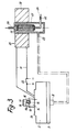
- Fig. 3 einen Schnitt durch eine Gesamtanordnung.
- Wie aus der Zeichnung Fig. 1 und 2 ersichtlich ist, wird die Druckkammer 1 gebildet durch die beiden miteinander verbundenen Gehäuseteile 2 und 3, insbes. aus Kunststoff mit eingebrachter Ausnehmung 4, in welcher eine tellerförmige Membrane 5, z.B. als Teflonmembrane eingespannt ist. Dieser Membrane 5 liegt einerseits der Plankopf 6 an, während andererseits der Ausnehmungsboden 7 mit Druckleitungsanschluß 8 liegt.
- Der Plankopf 6 sitzt auf zwei konzentrisch ineinanderliegenden Druckfedern 9a, 9b, welche vorzugsweise gegeneinander, z.B. mittels Isolierspirale 10, isoliert und durch den Schaltstrom 11 durchflossen sind, wodurch dieser bei Federbruch unterbrochen und damit der Druckleitungsanschluß 8 gesperrt wird, wie dies später geschildert ist.
- Der Plankopf 6 reicht mit seinem Führungsstößel 12 durch eine dem Gehäusedeckel 13 aufsitzende Hülse 14, welche durch Einwölbungen 15 für den Kunststoffschlauch als Schlauchdurchgeng 17 dient und mittels Umgriff 18 denselben (17) verschließt, solange die Druckkammer 1 nicht unter Gasdruck steht. Die Hülse 14 ist auf dem Gehäusedeckel befestigt oder auch mit diesem aus einem Stück und weist mit den beidseitigen Einwölbungen 15 als Schlauchdurchgang 17 mittig einen Quersteg 19 auf, welcher zusammen mit dem Umgriff 18 und Schlitzung 18a für den Quersteg 19 die Schlauckabklemmung 20 bewirkt.
- Es ist beidseits des Schlauchdurchgangs je eine Lichtschranke vorgesehen, welche bei im Schlauch 16 durchlaufender Flüssigkeit, wie Blut geöffnet sind und bei Durchtritt von Luftblasen schließen und dabei über eine hier nicht dargestellte Steuerung den Stromschalter 22 öffnen.
Beidseits am Schlauchdurchgang 17 sind übliche Halterungen zur Schlaucheinlage und -Entnahme vorgesehen, wie dies hier nicht besonders dargestellt ist. - Die Öffnung der Luftfalle, d.h. des Schlauchdurchgangs 17 des Kunststoffschlauchs 16 am Umgriff 18 erfolgt gegen die Wirkung der Feder 9a, 9b bei Beaufschlagung des Plankopfes 6 mit Membran 5 durch Gaseinlaß (bei 8) wird hierzu durch ein Dreiwegeventil 25 gesteuert, bei welchem bei Bestromung der Spule 26 der Magnetkern 27 den Gaseingang 28, z.B. von der Sauerstoffdruckflasche und Durchgang 29 zum Gaseinlaß 8 für die Druckkammer 1 öffnet und bei Stromunterbrechnung schließt und den Gasausgang 30 zur Atmosphäre öffnet.
Hierfür steht der Magnetkern 27 unter Wirkung der Feder 31, so daß er bei Stromunterbrechnung an der Spule 26 die Sperrung des Gaseingangs 29 unter zusätzlicher Sicherung durch sein Eigengewicht bewirkt und den Gasausgang 30 zur Atmosphäre öffnet, wie dies schematisch in der Zeichnung nach Figur 3 dargestellt ist. Im übrigen ist der Gaseingang 28 gegenüber dem Durchgang 29 und Gasausgang 30 bei 32 gedrosselt, damit bei gebrochener Feder 31 der Gas strom soweit gedrosselt wird, daß der Überdruck in der Leitung durch den induzierten pneumatischen Widerstand nicht ausreicht, um die Luftfalle zu öffnen bzw. beim Abschalten des Magnetventils der vorhandene Überdruck durch Leitung 30 mit dem zuströmenden Gas aus Leitung 28 gegen die Atmosphäre entlüftet werden kann. Das Eigengewicht des Magnetkerns 27 ist dabei größer zu wählen als die pneumatische Anpreßkraft zu Leitung 30. - Eine weitere Reflektions-Lichtschranke 33 kann von der Oberfläche 6a des Plankopfes 6 gesteuert werden und zwar vergeht zwischen dem gedrosselten (32) Gaseingang 28 bei Betätigung des Magnetkerns 27 durch Bestromung der Spule 26 und dem Füllen der Druckkammer 1 mit Betätigung des an der Membrane 5 anliegenden Plankopfes 6 gegen Wirkung der Feder 9a, 9b zum vollen Öffnen des Schlauchdurchgangs 17 der Luftfalle mittels Umgriff 18 eine vorbestimmte Zeit. Wird nun diese vorgegebene Zeit unterschritten, so sind die Federn 9a, 9b bzw. eine hiervon entweder erlahmt oder gebrochen und die Abklemmung am Schlauchdurchgang 17 wird in diesem Falle durch eine entsprechende Zeitmeß-Vergleichssteuerung durch Entlüftung der Druckkammer 1, z.B. über Stromabschaltung an der Spule 26 bewirkt. Diese Anordnung kann zusätzlich zu der Stromdurchgangsüberwachung der Federn 9a, 9b, wie vorgeschildert, zur Funktionssicherheit der Luftfalle eingebaut werden.
- Zufolge des großflächigen Plankopfs arbeitet diese Luftfalle mit geringeren Drücken; im übrigen läßt sich die Gesamtanordnung bei entspr. kürzeren Druckfedern flacher bauen als in der Zeichnung dargestellt.
- In der DE-PS 36 27 011 sind beispielsweise beidseitige Lichtschranken am Schlauchdurchgang 17 in perspektivischer Darstellung, weich auch Schlauchhalterungen auf beiden Seiten (von 17) gezeigt.
Claims (8)
gekennzeichnet durch einen Plankopf (Pilzkopf), welcher unter Federwirkung einerseits der Membrane einer Druckkammer ansteht, während er andererseits mit seinem Führungsstößel einen Schlauchdurchgang umgreift, derart, daß der Schlauchdurchgang bei unter Gasdruck stehender Kammer freigegeben und bei druckfreier Kammer durch den Führungsstößel mit Umgriff unter Federwirkung abgeklemmt ist.
dadurch gekennzeichnet, daß die Druckkammer gebildet wird durch zwei miteinander verbundene Gehäuseteile, insbes. Kunststoffgehäuse mit eingebrachter Ausnehmung, in welche eine tellerförmige Membrane eingespannt ist, der einerseits der Plankopf anliegt, während andererseits der Ausnehmungsboden mit Druckleitungsanschluß liegt.
dadurch gekennzeichnet, daß der Plankopf auf zwei konzentrisch ineinanderliegenden Druckfedern sitzt, welche vorzugsweise gegeneinander isoliert sind und durch den Schaltstrom durchflossen werden, derart, daß sie diesen bei Bruch unterbrechen und damit den Gaseinlaß sperren.
dadurch gekennzeichnet, daß der Plankopf mit seinem Führungsstößel durch eine dem Gehäusedeckel aufsitzende Hülse, welche als Schlauchdurchgang dient, reicht und mittels Umgriff den Schlauchdurchgang verschließt.
dadurch gekennzeichnet, daß die Hülse mit beidseitigen Einwölbungen als Schlauchdurchgang mittig einen Quersteg aufweist, welcher zusammen mit dem Umgriff die Schlauchabklemmung bewirkt.
dadurch gekennzeichnet, daß beidseits des Schlauchdurchgangs je eine Lichtschranke angeordnet ist, welche jede bei im Schlauch durchlaufenden Farbflüssigkeit geöffnet ist und bei Durchtritt von Luftblasen schließt und zusätzlich über eine Steuerung den Gaßeinlaß sperrt.
dadurch gekennzeichnet, daß am Schlauchdurchgang beidseits Halterungen zur Schlaucheinlage und -Entnahme vorgesehen sind.
dadurch gekennzeichnet, daß in der Gehäuseausnehmung (-Deckel) eine Reflektionslichtschranke eingebaut ist, welche von der Plankopfrückseite betätigt in Verbindung mit einer Zeitmeß- Vergleichssteuerung zum gedrosselten Lufteintritt bei Abweichung die Entlüfung der Druckkammer bewirkt.
Applications Claiming Priority (2)
| Application Number | Priority Date | Filing Date | Title |
|---|---|---|---|
| DE19883801577 DE3801577A1 (de) | 1986-08-09 | 1988-01-21 | Luftfalle zur absperrung von kunststoffschlaeuchen, insbes. infusionsschlaeuchen |
| DE3801577 | 1988-01-21 |
Publications (3)
| Publication Number | Publication Date |
|---|---|
| EP0325186A2 true EP0325186A2 (de) | 1989-07-26 |
| EP0325186A3 EP0325186A3 (de) | 1991-01-23 |
| EP0325186B1 EP0325186B1 (de) | 1994-10-05 |
Family
ID=6345643
Family Applications (1)
| Application Number | Title | Priority Date | Filing Date |
|---|---|---|---|
| EP19890100653 Expired - Lifetime EP0325186B1 (de) | 1988-01-21 | 1989-01-16 | Einrichtung zur Absperrung von Kunststoffschläuchen, insbesondere Infusionsschläuchen,für Luftfallen |
Country Status (4)
| Country | Link |
|---|---|
| US (1) | US4925152A (de) |
| EP (1) | EP0325186B1 (de) |
| AT (1) | ATE112493T1 (de) |
| ES (1) | ES2064370T3 (de) |
Families Citing this family (35)
| Publication number | Priority date | Publication date | Assignee | Title |
|---|---|---|---|---|
| US5290239A (en) * | 1991-09-26 | 1994-03-01 | Baxter International, Inc. | Intravenous tube safety apparatus |
| US5350357A (en) * | 1993-03-03 | 1994-09-27 | Deka Products Limited Partnership | Peritoneal dialysis systems employing a liquid distribution and pumping cassette that emulates gravity flow |
| US5324422A (en) * | 1993-03-03 | 1994-06-28 | Baxter International Inc. | User interface for automated peritoneal dialysis systems |
| ATE170759T1 (de) * | 1993-03-03 | 1998-09-15 | Deka Products Lp | Vorrichtung zur peritonaldialyse mit einer zur luftabscheidung ausgerüsteten flüssigkeitsverteil- und pumpenkassette. |
| US5438510A (en) * | 1993-03-03 | 1995-08-01 | Deka Products Limited Partnership | User interface and monitoring functions for automated peritoneal dialysis systems |
| US5431626A (en) * | 1993-03-03 | 1995-07-11 | Deka Products Limited Partnership | Liquid pumping mechanisms for peritoneal dialysis systems employing fluid pressure |
| US5474683A (en) * | 1993-03-03 | 1995-12-12 | Deka Products Limited Partnership | Peritoneal dialysis systems and methods employing pneumatic pressure and temperature-corrected liquid volume measurements |
| US5445613A (en) * | 1993-07-16 | 1995-08-29 | Rocky Mountain Research, Inc. | Condition detection system and clamp |
| US5453098A (en) * | 1994-05-09 | 1995-09-26 | Imed Corporation | Two step IV fluid flow stop |
| US5967484A (en) * | 1995-12-21 | 1999-10-19 | Alaris Medical Systems, Inc. | Intravenous tube occluder |
| US5954485A (en) * | 1996-08-14 | 1999-09-21 | Sims Deltec, Inc. | Free-flow protection devices and methods |
| DE10017847C1 (de) * | 2000-04-11 | 2002-04-25 | Stoeckert Instr Gmbh | Herz-Lungen-Maschine mit druckmittelbetätigten Steuerorganen |
| US6520493B2 (en) | 2001-03-16 | 2003-02-18 | Lord Corporation | Lift support strut with directional damping |
| ITMI20020359A1 (it) * | 2002-02-22 | 2003-08-22 | Gambro Lundia Ab | Metodo di controllo dell'operativita' di un organo di interdizione del flusso e dispositivo di arresto del flusso per un circuito extracorpo |
| US6929751B2 (en) * | 2002-05-24 | 2005-08-16 | Baxter International Inc. | Vented medical fluid tip protector methods |
| US7175606B2 (en) | 2002-05-24 | 2007-02-13 | Baxter International Inc. | Disposable medical fluid unit having rigid frame |
| US6814547B2 (en) * | 2002-05-24 | 2004-11-09 | Baxter International Inc. | Medical fluid pump |
| US7153286B2 (en) | 2002-05-24 | 2006-12-26 | Baxter International Inc. | Automated dialysis system |
| US7238164B2 (en) | 2002-07-19 | 2007-07-03 | Baxter International Inc. | Systems, methods and apparatuses for pumping cassette-based therapies |
| US11273245B2 (en) | 2002-07-19 | 2022-03-15 | Baxter International Inc. | Dialysis system having a vented disposable dialysis fluid carrying member |
| JP4691503B2 (ja) | 2003-10-28 | 2011-06-01 | バクスター・インターナショナル・インコーポレイテッド | 医療用流体システムのための、改善されたプライミング、一体性および水頭高さの方法および装置 |
| US7632078B2 (en) | 2003-10-30 | 2009-12-15 | Deka Products Limited Partnership | Pump cassette bank |
| US8029454B2 (en) | 2003-11-05 | 2011-10-04 | Baxter International Inc. | High convection home hemodialysis/hemofiltration and sorbent system |
| US7776006B2 (en) * | 2003-11-05 | 2010-08-17 | Baxter International Inc. | Medical fluid pumping system having real time volume determination |
| EP1832303A1 (de) * | 2004-11-24 | 2007-09-12 | LIFEBRIDGE Medizintechnik AG | Vorrichtung zur Bereitstellung eines extrakorporalen Blutkreislaufs |
| US8834399B2 (en) | 2010-12-07 | 2014-09-16 | Zoll Lifebridge Gmbh | Cardiopulmonary apparatus and methods for preserving organ viability |
| US8715235B2 (en) * | 2007-07-05 | 2014-05-06 | Baxter International Inc. | Dialysis system having disposable cassette and heated cassette interface |
| US7909795B2 (en) * | 2007-07-05 | 2011-03-22 | Baxter International Inc. | Dialysis system having disposable cassette and interface therefore |
| US7905853B2 (en) | 2007-10-30 | 2011-03-15 | Baxter International Inc. | Dialysis system having integrated pneumatic manifold |
| US8062513B2 (en) | 2008-07-09 | 2011-11-22 | Baxter International Inc. | Dialysis system and machine having therapy prescription recall |
| US9514283B2 (en) | 2008-07-09 | 2016-12-06 | Baxter International Inc. | Dialysis system having inventory management including online dextrose mixing |
| CA2819792A1 (en) | 2010-12-07 | 2012-06-14 | Zoll Lifebridge Gmbh | Method and system for filling and venting a device for extracorporeal blood treatment, with stepped flooding of a filter |
| US9127781B2 (en) | 2013-04-08 | 2015-09-08 | Pbm Valve, Inc. | Pinch valve |
| WO2014169428A1 (zh) * | 2013-04-16 | 2014-10-23 | 福建省百仕韦医用高分子股份有限公司 | 止流夹装置 |
| GB2540176A (en) * | 2015-07-08 | 2017-01-11 | Li Jianhe | Dry powder inhaler apparatus |
Family Cites Families (7)
| Publication number | Priority date | Publication date | Assignee | Title |
|---|---|---|---|---|
| US2986160A (en) * | 1956-09-04 | 1961-05-30 | Union Carbide Corp | Pinch valves |
| US3823724A (en) * | 1973-05-25 | 1974-07-16 | Med Lab Computer Services Inc | Controlling flow of medical fluids |
| US3882899A (en) * | 1973-07-26 | 1975-05-13 | Coulter Electronics | Pinch valve construction |
| GB2147394B (en) * | 1983-09-30 | 1987-07-15 | Ben Joseph Gallant | Tube flow shut-off device |
| ATE37793T1 (de) * | 1983-12-27 | 1988-10-15 | Pfister Lehmann Alfred | Verschluss an einem harnkatheter. |
| SE459641B (sv) * | 1986-03-24 | 1989-07-24 | Gambro Ab | Detektorsystem foer kontroll av en foer ledning av blod alternerande med en vaesentligen faergloes vaetska avsedd vaetskeslang |
| DE3627011A1 (de) * | 1986-08-09 | 1988-02-18 | Huebner Karl Alexander | Luftfalle zur absperrung von kunststoffschlaeuchen, insbes. infusionsschlaeuchen |
-
1989
- 1989-01-16 ES ES89100653T patent/ES2064370T3/es not_active Expired - Lifetime
- 1989-01-16 AT AT89100653T patent/ATE112493T1/de not_active IP Right Cessation
- 1989-01-16 EP EP19890100653 patent/EP0325186B1/de not_active Expired - Lifetime
- 1989-01-19 US US07/299,883 patent/US4925152A/en not_active Expired - Fee Related
Also Published As
| Publication number | Publication date |
|---|---|
| ES2064370T3 (es) | 1995-02-01 |
| US4925152A (en) | 1990-05-15 |
| ATE112493T1 (de) | 1994-10-15 |
| EP0325186B1 (de) | 1994-10-05 |
| EP0325186A3 (de) | 1991-01-23 |
Similar Documents
| Publication | Publication Date | Title |
|---|---|---|
| EP0325186A2 (de) | Einrichtung zur Absperrung von Kunststoffschläuchen, insbesondere Infusionsschläuchen,für Luftfallen | |
| DE69300301T2 (de) | Ventilanordnung für Gasbehälter. | |
| EP0788591B1 (de) | Anschlusssystem für eine druckgasflasche | |
| DE4135993C2 (de) | Magnetventil in Baukastenbauweise | |
| EP0296618B1 (de) | Selbstschliessender Kraftstoffbehälterverschluss | |
| DE3627011C2 (de) | ||
| DE3533304A1 (de) | Stroemungsregeleinrichtung | |
| EP0458253B1 (de) | Absperrorgan für einen unter Innendruck eines Mediums stehenden Druckbehälter | |
| DE2513490A1 (de) | Druckabhaengige ventilanordnung | |
| WO1995015574A1 (de) | Elektromagnetisches schaltgerät | |
| DE19812961C2 (de) | Ventilkuppelstück | |
| EP0038978A2 (de) | Druckregelvorrichtung mit Anzeige für mindestens zwei miteinander druckseitig verbundene Druckgefässe | |
| DE3626825A1 (de) | Rohrtrennung mit einer sperreinrichtung und eine ueberwachungseinrichtung fuer die sperreinrichtung | |
| DE60116728T2 (de) | Sicherheitsvorrichtung für eine Rohrleitungsarmatur | |
| EP0437733B1 (de) | Vorrichtung zum Reinigen und Entleeren von Flüssigkeitsleitungen, insbesondere Getränkeleitungen in Zapfanlagen | |
| DE3801577A1 (de) | Luftfalle zur absperrung von kunststoffschlaeuchen, insbes. infusionsschlaeuchen | |
| EP2198684A1 (de) | Schaltventilgehäuse und Düsenträger für Spritzvorrichtung für die Landtechnik | |
| EP1013986B1 (de) | Gasflaschenarmatur | |
| DE19731744C1 (de) | Blutentnahmevorrichtung | |
| DE19819852C2 (de) | Rohrtrennvorrichtung und hydraulisch angetriebene Hebevorrichtung mit einer solchen Rohrtrennvorrichtung | |
| AT391179B (de) | Ventilbaugruppe | |
| DE2745293A1 (de) | Nachgiebige verbindungsanordnung | |
| DE3137530A1 (de) | Tuerbetaetigungseinrichtung | |
| EP2071086A1 (de) | Ab- und Überlaufvorrichtung | |
| DE7617232U1 (de) | Vorrichtung zum verriegeln von tueren, insbesondere brandschutztueren |
Legal Events
| Date | Code | Title | Description |
|---|---|---|---|
| PUAI | Public reference made under article 153(3) epc to a published international application that has entered the european phase |
Free format text: ORIGINAL CODE: 0009012 |
|
| AK | Designated contracting states |
Kind code of ref document: A2 Designated state(s): AT ES FR GB IT SE |
|
| PUAL | Search report despatched |
Free format text: ORIGINAL CODE: 0009013 |
|
| AK | Designated contracting states |
Kind code of ref document: A3 Designated state(s): AT ES FR GB IT SE |
|
| 17P | Request for examination filed |
Effective date: 19910617 |
|
| 17Q | First examination report despatched |
Effective date: 19920923 |
|
| GRAA | (expected) grant |
Free format text: ORIGINAL CODE: 0009210 |
|
| AK | Designated contracting states |
Kind code of ref document: B1 Designated state(s): AT ES FR GB IT SE |
|
| REF | Corresponds to: |
Ref document number: 112493 Country of ref document: AT Date of ref document: 19941015 Kind code of ref document: T |
|
| ITF | It: translation for a ep patent filed | ||
| PG25 | Lapsed in a contracting state [announced via postgrant information from national office to epo] |
Ref country code: SE Effective date: 19950105 |
|
| PG25 | Lapsed in a contracting state [announced via postgrant information from national office to epo] |
Ref country code: AT Effective date: 19950116 |
|
| REG | Reference to a national code |
Ref country code: ES Ref legal event code: FG2A Ref document number: 2064370 Country of ref document: ES Kind code of ref document: T3 |
|
| GBT | Gb: translation of ep patent filed (gb section 77(6)(a)/1977) |
Effective date: 19950112 |
|
| ET | Fr: translation filed | ||
| PLBE | No opposition filed within time limit |
Free format text: ORIGINAL CODE: 0009261 |
|
| STAA | Information on the status of an ep patent application or granted ep patent |
Free format text: STATUS: NO OPPOSITION FILED WITHIN TIME LIMIT |
|
| 26N | No opposition filed | ||
| PGFP | Annual fee paid to national office [announced via postgrant information from national office to epo] |
Ref country code: GB Payment date: 19970113 Year of fee payment: 9 |
|
| PGFP | Annual fee paid to national office [announced via postgrant information from national office to epo] |
Ref country code: ES Payment date: 19970124 Year of fee payment: 9 |
|
| PGFP | Annual fee paid to national office [announced via postgrant information from national office to epo] |
Ref country code: FR Payment date: 19970128 Year of fee payment: 9 |
|
| PG25 | Lapsed in a contracting state [announced via postgrant information from national office to epo] |
Ref country code: GB Free format text: LAPSE BECAUSE OF NON-PAYMENT OF DUE FEES Effective date: 19980116 |
|
| PG25 | Lapsed in a contracting state [announced via postgrant information from national office to epo] |
Ref country code: ES Free format text: LAPSE BECAUSE OF NON-PAYMENT OF DUE FEES Effective date: 19980117 |
|
| PG25 | Lapsed in a contracting state [announced via postgrant information from national office to epo] |
Ref country code: FR Free format text: THE PATENT HAS BEEN ANNULLED BY A DECISION OF A NATIONAL AUTHORITY Effective date: 19980131 |
|
| GBPC | Gb: european patent ceased through non-payment of renewal fee |
Effective date: 19980116 |
|
| REG | Reference to a national code |
Ref country code: FR Ref legal event code: ST |
|
| REG | Reference to a national code |
Ref country code: ES Ref legal event code: FD2A Effective date: 20000503 |
|
| PG25 | Lapsed in a contracting state [announced via postgrant information from national office to epo] |
Ref country code: IT Free format text: LAPSE BECAUSE OF NON-PAYMENT OF DUE FEES;WARNING: LAPSES OF ITALIAN PATENTS WITH EFFECTIVE DATE BEFORE 2007 MAY HAVE OCCURRED AT ANY TIME BEFORE 2007. THE CORRECT EFFECTIVE DATE MAY BE DIFFERENT FROM THE ONE RECORDED. Effective date: 20050116 |