EP0325206A2 - Beschichtungsvorrichtung - Google Patents
Beschichtungsvorrichtung Download PDFInfo
- Publication number
- EP0325206A2 EP0325206A2 EP89100729A EP89100729A EP0325206A2 EP 0325206 A2 EP0325206 A2 EP 0325206A2 EP 89100729 A EP89100729 A EP 89100729A EP 89100729 A EP89100729 A EP 89100729A EP 0325206 A2 EP0325206 A2 EP 0325206A2
- Authority
- EP
- European Patent Office
- Prior art keywords
- slit
- coating
- edge surface
- support
- back edge
- Prior art date
- Legal status (The legal status is an assumption and is not a legal conclusion. Google has not performed a legal analysis and makes no representation as to the accuracy of the status listed.)
- Granted
Links
Images



Classifications
-
- B—PERFORMING OPERATIONS; TRANSPORTING
- B05—SPRAYING OR ATOMISING IN GENERAL; APPLYING FLUENT MATERIALS TO SURFACES, IN GENERAL
- B05C—APPARATUS FOR APPLYING FLUENT MATERIALS TO SURFACES, IN GENERAL
- B05C5/00—Apparatus in which liquid or other fluent material is projected, poured or allowed to flow on to the surface of the work
- B05C5/02—Apparatus in which liquid or other fluent material is projected, poured or allowed to flow on to the surface of the work the liquid or other fluent material being discharged through an outlet orifice by pressure, e.g. from an outlet device in contact or almost in contact, with the work
- B05C5/0254—Coating heads with slot-shaped outlet
- B05C5/0262—Coating heads with slot-shaped outlet adjustable in width, i.e. having lips movable relative to each other in order to modify the slot width, e.g. to close it
Definitions
- This invention relates to an extrusion type coating apparatus, specifically one which is capable of high speed, high viscosity coating and thin coatings for trouble-free magnetic medium coating.
- Coating methods such as roll, gravure, extrusion, slide guard, curtain, and other various methods are well known.
- Magnetic recording media are obtained by coating the media support with magnetic coating solution. Coating methods such as roll, gravure coat, and extrusion coat are commonly used for magnetic media. Extrusion coating provides a particularly uniform coating film thickness.
- Troubles which become significant problems under these types of coating conditions and especially at the time of thin film coating include an exfoliation trouble in which a coating film is peeled off by a substance adhesing or sticking on a back edge surface, such as foreign matter on the media support, dust and condensed substances in coating solutions, a thickness trouble in which a thickness of coating film becomes partially thicker, and a base waste troulbe in which the base waste is generated by shaving the support with the corner at the front edge especially on the downstream side and adheres on a coated surface, etc.
- irregularities on the supporting member are apt to cause intersecting streaks, which in turn cause noise or output level fluctuation.
- the first objective of this invention is to provide a coating system which has less adherence of base waste.
- the uniformity of film thickness of the magnetic recording medium formed by coating has a large influence on recording and reproducing characteristics.
- the film thickness in the running direction can be basically controlled by the coating speed (support carrying speed) and coating solution supply speed.
- the film thickness in the width direction should be even if the contact strength of the support to the coater head is even in the width direction.
- tension in the width direction to the support during coating varies and scars or creases on the support often make the film thickness of the coating vary in the width direction. This reduces the yield rate and the quality.
- the second objective of this invention is to provide a magnetic recording medium coating apparatus that can simplify uniform film thickness distribution in the width direction and yet not degrading the properties of the coating solution.
- the third objective of this invention is to provide a coating apparatus by which a magnetic recording medium with excellent electromagnetic properties can be obtained.
- the inventor et al of this invention investigated what factors in the selective condition range determine the coating ability, and found that certain of the fluidity of the coating solution in the slits determines the coating ability and especially the electromagnetic properties, as well as the contour of the front edge or back edge surfaces. Especially with magnetic or metal particles with BET values of greater than 50m2/g, the fluidity of the coating solution at the slits exerts a large influence.
- reducing the slit gap between the front edge surface and back edge surface increases the speed of the running solution under a predetermined film thickness or a predetermined coating solution flow rate.
- the coating solution preliminary shearing device which is presented in Japanese Patent Publiction O.P.I. No. 54766/1985 is used so that a large pressure loss occurs, the result is as follows: --- when the slit gap is less than 50 ⁇ m, the pressure acting on this device is more than 4 kg/cm2 and trouble is likely to occur in the mechanical seals throughout this device and in the solution feeding system. When forming a slit, if the gap is less than 50 ⁇ m, the machining accuracy of the slit surface will cause immediate pressure variation of the coating solution which is flowing out.
- the fourth objective of this invention is to provide a coating apparatus which achieves satisfactory electronmagnetic properties for the magnetic recording medium during coating so that film thickness variation is insignificant, and pressure loss is small.
- the second objective of this invention to simplify uniform distribution of the film thickness in the width direction, is attained by providing a gap adjusting measn in the above described slit with at least 3 places in the width direction so that the slit gap can be appropriately adjusted.
- the second objective can be attained in the same way as described above with a heating means in which a heating mechanism to heat the coating solution passing through the above described slit is provided at 3 places in the width direction so as to control those heating temperature. That is, when the coating solution passing through the slit is heated by the heating means, the viscosity of the coating solution decreases accordingly. Coating film thickness varies depending on the viscosity.
- the film thickness in the width direction can be made uniform by providing at least 3 heating means in the width direction and by controlling the temperature of the coating solution.
- the second objective can be also attained in a coating apparatus comprising a coater head to extrude coating solution continuously from the slit between the above described front edge surface and back edge surface to the surface of the flexible support running continuously along the front edge surface and back edge surface, thereby coating the above described support surface with the coating solution, a pair of guide roller disposed on the upstream and downstream sides of the coater head to push the above described support to the coater head side, and a tension adjusting means provided between the coater head and at least one guide roll to guide the support while making the width of support curved.
- the tension of the support is stronger at the center and weaker on both sides.
- uneven tension can be rectified by employing a tension adjusting mechanism with a mountain-shaped guide surface as described above.
- the tension adjuster can be composed of a hand drum-shaped roll and is practical with respect to cost and other points. It is also advantageous since it does not influence the properties of the coating solution.
- Recording means which have exellent electromagnetic properties can be attained in a coating apparatus with a coater head which extrudes coating solution continuously from the slit between the above described front and back edge surface to the flexible support a surface along the same surfaces and coasts the above described support surface, and a pair of support rolls to push the above described support towards the coater head side on the upperstream and downstream sides of the coater head, when the angle, ⁇ , made by the running direction line connecting the surface of the upstream and downstream support rolls on the coater head sides and the tengential line at the downstream edge on the above-described back edge surface, is 0.5° ⁇ ⁇ ⁇ 10°.
- the fourth objective of this invention is to provide, a coating apparatus which achieves satisfactory electromagnetic properties of the magnetic recording medium such that, film thickness variation is small, and pressure loss is low.
- This can be realized in an apparatus which extrudes a coating solution continuously from the slit of the above described front edge surface and back edge surface to the flexible support surface which runs continuously along said surface and applies the coating solution to the above described support surface, when at least a certain length of the slit's outlet is tapered towards the outlet end, the angle of the intersecting tapered surfaces is 3° - 20°, and the outlet end gap is less than 200 ⁇ m.
- the wall 3A and 3B of the slit 3 are tapered for a certain range of the slit's outlet and their intersecting angle 1 is 3° -10°. Therefore the flow rate is higher at the slit outlet end than with parallel slit surfaces under a certain set coating solution flow rate. Therefore, while the running speed at the outlet end should be more than a certain value in order not to reduce the electromagnetic conversion characteristics of the magnetic recording medium, sufficient outlet end flow rate can be obtained and the desired electromagnetic conversion characters can be satisfied.
- the slit wall is tapered, pressure loss is greatly reduced, even making the troubles inherent in using the above described pre-coating shearing apparatus negligible.
- film thickness variation in the sheet width direction can be great if the entire slit surface machining accuracy is not high.
- the film thickness variation in the sheet width direction is influenced only by the machining accuracy at the outlet end of the slit and since desired machining accuracy is easy to maintain if limited to the slit outlet end only, film thickness variation in the sheet width direction can be reduced.
- Fig. 1 shows the major part of an extruder related to this invention with front edge surface 1 on the upstream side surface and back edge surface 2 on the downstream side surface, and slit 3 between them which is interconnected with the coating solution pocket 4 (refer to Fig. 16).
- part of the back edge 2 projects (approximately upward in Fig. 1) from the tangent line 1 at the downstream end B of the front edge surface 1.
- the support comes up along front edge 1 as shown by the arrow mark, passes through the downstream end B, crosses over slit 3 and solution reservoir 5, and goes to the right, moving over the coating soultion tank on the back edge surface 2.
- the downstream ends A and B seem to form substantially sharp edges or sharp corners. However, it may be preferable to round off such sharp edges. In this case where the sharp edge is rounded off, the downstream end is the sharp edge point before beeing rounded off. Therefore, after shaping the roundness, the downstream end is obtained as a cross point between extension lines of surfaces being not rounded off.
- Optimum redius of curvature of the back edge surface 2 is 3 - 10mm.
- plastic film such as polyester film, etc., paper, their laminated sheets, metal sheets, etc., and any plastic materials, can be used.
- the effect of this invention is clearly manifested in the magnetic coating solution, especially one of more than 1000cps (measured value of B type viscometer with 60 turns, after 1 minute), but a photosensitive coating solution may be used.
- the best effect is manifested at speeds as high as 150m/minute or more.
- Coating was conducted for 10000m and coating ability was evaluated by counting the number of streaks and the adherence number of base waste (average number per width 1m and length 10m).
- Table 1 Coating speed Previous technology Apparatus of this invention Streaks Adhered base waste Streaks Adhered base waste 100 m/min. 0 101 0 9 150 m/min. 1 243 0 21 200 m/min 2 504 1 23
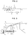
- film thickness gauge 8 (an X-ray film thickness gauge) is provided on the outside of the coater head CH and information on coating film thickness obtained by this film thickness gauge 8 is supplied to computing unit 9.
- Computing unit 9 outputs correction signal to motor controller 10 attached to each gap adjusting means 7, 7 ... to make the current film thickness distribution in the width direction even. At this time, computing unit 9 outputs a correction signal based on the current slit gap, current viscosity of coating solution, coating solution flow rate, desired film thickness, and coating speed, detected using the current rotating angle (current position) of the adjusting threaded bar, Magnetscale (trade name, not illustrated), based on output of the stepping motor 74.
- the gap may also be adjusted by providing a gap adjusting member with a different thermal expansion coefficient from that of the front edge and back edges, extending over the said edges through the slit, arranging a heater in the inside, converting the signal from the film thickness gauge to the temperature control signal to adjust the heater temperature, and thereby expand or contract the gap adjusting member.
- the coating film thickness varies in the width direction at the center and on both sides, at least 3 means to adjust the gap are necessary.
- film thickness distribution in the width direction was compared using the coating apparatus of this invention as shown in the figure.
- the same coating apparatus without gap adjustment was installed.
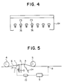
- Figs. 5 to 7 show another actual model to attain the second object.
- heaters 17, 17 ... as the heating means of this invention are arranged at equal intervals in the width direction of the support, that is in the width direction of the coater head CH, directly to the above described slit 3 or indirectly through the coater head CH forming member.
- a film thickness gauge 8 such as an X-ray film thickness gauge, is provided on the outlet side of the coater head CH, and information on coating film thickness obtained by this film thickness gauge 8 is taken into the computing unit 9.
- Computing unit 9 outputs a correction signal to each temperature adjusting apparatus 10 attached to each heater 17 to make the current film thickness distribution in the width direction even according to the coating film thickness signal. At this time, computing unit 9 oututs a correction signal based on the current power supply volume, current viscosity of the coating solution, coating solution flow rate, desired film thickness, and coating, etc. as well as the current film thickness distribution.
- film thickness distribution is made even in the width direction.
- Heater 17 may be provided on the back edge side. Multiple numbers may be provided in the direction towards to outlet of slit 3. Since the film thickness varies at the center and both sides in the width direction, at least 3 heaters are required in the width direction.
- a magnetic recording medium sheet was obtained by high viscosity magnetic coating solution of 2500cps with metal particles (BET value 60m3/g) to wet film of 15 ⁇ m in thickness.
- Film thickness distribution in the width direction was compared using the coating apparatus of this invention as shown in the figure and an identical coating apparatus without heating.
- FIGs. 8 and 9 show still another actual model to attain the second object.
- a hand drum-shaped tension adjusting roll 27 is provided between the coater head CH and upstream guide roll 4 and support 6 is pushed and guided by adjusting roll 27.
- unit adjusting rolls 27A and 27B arranged in recessed configuration as shown in Fig. 10 may be pushed against support 6 as another preferable emodiment.
- drum shaped adjusting roll 27 and the drum-shaped adjusting roll 27′ as shown in Fig. 11 side by side along the running direction of the supporter 6 so as to guide the support so that tension can be controlled more accurately in the width direction than when using one adjusting roll.
- the drum-shaped adjusting roll 27′ may be used independently.
- the above adjusting rolls may be provided between the coater head CH and downstream guide roll 5.
- the tension adjusting means may not be a roll and may be the bottom of the secured block formed in the projected configuration. In this case, support 6 runs on the bottom surface in sliding contact with it.
- film thickness distribution in the width direction was compared using the coating apparatus of this invention as shown in Figs. 8 and 9 and using the same coating apparatus without tension control.
- the distance between the downstream end A of the back edge surface 2 and the center of the downstream support roll 5 should be between 5 and 100mm. When it is below 5 mm, support 6 may turn direction suddenly at the downstream end A on the back edge surface and flatness of the coating film is damaged, or when it exceeds 100mm, the pushing force of the support 6 is reduced, leading to variation in film thickness.
- the progressing direction of support 6 to the upstream support roll 4 and the direction after leaving the downstream support roll 5 are not limited.
- the magnetic recording medium sheet was obtained by coating with a high viscosity magnetic coating solution of 3000cps having metal particles (BET value 60m3/g) to wet film of 30 ⁇ m in thickness.
- Coating film uniformity is favorable in this invention and therefore favorable RF out and Lumi S/N values are anticipated.
- a small variation in the audio output is considered because of the small variation of the film thickness in the sheet length direction.
- the average flow velocity can be measured easily in this invention since the magnetic coating solution can be handled in the same way as laminar flow.
- the coating solution viscosity the measurement value of a B type viscometer after 60 revolutions, 1 minute (at room temperature) can be used.
- polyester terephthalate of 15 ⁇ m as the support, magnetic coating solutions of various viscosity with metal powder (BET value 60m3/g) were coated changing the slit width and average flow velocity to obtain 100 ⁇ m of wet film thickness in the coating apparatus in Fig. 1 in order to produce a magnetic recording medium sheet.
- Electromagnetic conversion characteristics of the sheet obtained were investigated. The result is shown in Table 3 and Fig. 13.
- Fig. 14 shows the main portion of the extruder used in this actual model, with front edge surface 1 on the surface on the upstream side, back edge surface 2 on the surface on the downstream side, and slit 3 between them interconnecting with the coating solution pocket.
- slit 3 is in parallel at the base and thus the whole surface should not be necessarily tapered.
- the above described coating apparatus of this invention and a coating apparatus as presented in the official gazette for the patent publication No. SHO60-238179 were prepared, with slit gaps (the slit gap of the actual model is D as described above) of 50 ⁇ m and 100 ⁇ m. Electromagnetic properties RF out, variation of film thickness in the width direction and pressure loss at the time of coating the obtained sheet were investigated and the result shown in Table 4 was obtained.
- Coating was conducted for 10000m respectively and the coating efficiency was evaluated by counting the number of pin holes, streaks, and adherence of base waste for the entire length.
Landscapes
- Application Of Or Painting With Fluid Materials (AREA)
- Coating Apparatus (AREA)
- Manufacturing Of Magnetic Record Carriers (AREA)
Applications Claiming Priority (4)
| Application Number | Priority Date | Filing Date | Title |
|---|---|---|---|
| JP63010286A JP2598937B2 (ja) | 1988-01-20 | 1988-01-20 | 塗布装置および塗布方法 |
| JP63010287A JP2639670B2 (ja) | 1988-01-20 | 1988-01-20 | 塗布装置および塗布方法 |
| JP10286/88 | 1988-01-20 | ||
| JP10287/88 | 1988-01-20 |
Publications (3)
| Publication Number | Publication Date |
|---|---|
| EP0325206A2 true EP0325206A2 (de) | 1989-07-26 |
| EP0325206A3 EP0325206A3 (en) | 1990-08-01 |
| EP0325206B1 EP0325206B1 (de) | 1995-04-19 |
Family
ID=26345540
Family Applications (1)
| Application Number | Title | Priority Date | Filing Date |
|---|---|---|---|
| EP89100729A Expired - Lifetime EP0325206B1 (de) | 1988-01-20 | 1989-01-17 | Beschichtungsvorrichtung |
Country Status (3)
| Country | Link |
|---|---|
| US (1) | US5042422A (de) |
| EP (1) | EP0325206B1 (de) |
| DE (1) | DE68922228T2 (de) |
Cited By (2)
| Publication number | Priority date | Publication date | Assignee | Title |
|---|---|---|---|---|
| EP0661102A1 (de) * | 1993-12-28 | 1995-07-05 | TDK Corporation | Beschichtungsverfahren und Beschichtungsvorrichtung |
| WO1997021494A1 (en) * | 1995-12-08 | 1997-06-19 | Young Gak Choi | Coating device |
Families Citing this family (9)
| Publication number | Priority date | Publication date | Assignee | Title |
|---|---|---|---|---|
| JP2714850B2 (ja) * | 1989-04-07 | 1998-02-16 | コニカ株式会社 | 塗布装置および重層塗布方法 |
| JP2609174B2 (ja) * | 1990-10-08 | 1997-05-14 | 富士写真フイルム株式会社 | 塗布方法 |
| US5376178A (en) * | 1991-07-31 | 1994-12-27 | Sony Corporation | Coating apparatus |
| US5324357A (en) * | 1991-10-01 | 1994-06-28 | Konica Corporation | Extrusion coating apparatus |
| JP2902238B2 (ja) * | 1992-11-25 | 1999-06-07 | 花王株式会社 | 塗布装置及び方法 |
| US5547510A (en) * | 1993-04-08 | 1996-08-20 | Konica Corporation | Coating apparatus |
| CA2133266A1 (en) * | 1993-10-29 | 1995-04-30 | Hans-Jurgen Meissner | Slot coating die configuration |
| US20050233073A1 (en) * | 2004-04-19 | 2005-10-20 | The Procter & Gamble Company | Method and apparatus for applying coatings, for instance for sanitary products |
| US9579684B2 (en) | 2011-06-07 | 2017-02-28 | 3M Innovative Properties Company | Slot die position adjustment control |
Family Cites Families (11)
| Publication number | Priority date | Publication date | Assignee | Title |
|---|---|---|---|---|
| US2784697A (en) * | 1952-12-16 | 1957-03-12 | Enamelstrip Corp | Apparatus for coating metallic strips |
| US3609810A (en) * | 1968-10-14 | 1971-10-05 | Black Clawson Co | Web coating apparatus |
| NL6909118A (de) * | 1969-06-13 | 1970-12-15 | ||
| JPS5784771A (en) * | 1980-11-13 | 1982-05-27 | Fuji Photo Film Co Ltd | Coater |
| JPS6050133B2 (ja) * | 1981-11-05 | 1985-11-07 | 東芝機械株式会社 | 口金隙間調整方法 |
| JPS58205561A (ja) * | 1982-05-25 | 1983-11-30 | Fuji Photo Film Co Ltd | 塗布方法及び装置 |
| JPS60238179A (ja) * | 1984-05-14 | 1985-11-27 | Fuji Photo Film Co Ltd | 塗布装置 |
| US4912948A (en) * | 1985-03-22 | 1990-04-03 | Union Carbide Chemicals And Plastics Company Inc. | Vacuum guide used in flexible sheet material treatment |
| DE3541784C1 (de) * | 1985-11-26 | 1987-05-21 | Meltex Verbindungstechnik Gmbh | Vorrichtung zum Auftragen von fluessigem Klebstoff,insbesondere von Schmelzklber(hot melt) |
| US4781562A (en) * | 1986-08-12 | 1988-11-01 | Toshiba Kikai Kabushiki Kaisha | Heat displacing type dies |
| DE3628974C1 (de) * | 1986-08-26 | 1988-02-25 | Schmidt Erwepa Maschf | Breitschlitzduese zum Extrudieren von Thermoplasten |
-
1989
- 1989-01-17 DE DE68922228T patent/DE68922228T2/de not_active Expired - Lifetime
- 1989-01-17 EP EP89100729A patent/EP0325206B1/de not_active Expired - Lifetime
- 1989-01-17 US US07/297,756 patent/US5042422A/en not_active Expired - Lifetime
Cited By (3)
| Publication number | Priority date | Publication date | Assignee | Title |
|---|---|---|---|---|
| EP0661102A1 (de) * | 1993-12-28 | 1995-07-05 | TDK Corporation | Beschichtungsverfahren und Beschichtungsvorrichtung |
| US5597615A (en) * | 1993-12-28 | 1997-01-28 | Tdk Corporation | Extrusion coating method and coating apparatus for coating both sides of a web |
| WO1997021494A1 (en) * | 1995-12-08 | 1997-06-19 | Young Gak Choi | Coating device |
Also Published As
| Publication number | Publication date |
|---|---|
| DE68922228D1 (de) | 1995-05-24 |
| EP0325206A3 (en) | 1990-08-01 |
| EP0325206B1 (de) | 1995-04-19 |
| DE68922228T2 (de) | 1995-08-31 |
| US5042422A (en) | 1991-08-27 |
Similar Documents
| Publication | Publication Date | Title |
|---|---|---|
| EP0545084B1 (de) | Extrusionsartige Beschichtungsvorrichtung und Beschichtungsmethode | |
| EP0325206B1 (de) | Beschichtungsvorrichtung | |
| US6033723A (en) | Method and apparatus for coating plurality of wet layers on flexible elongated web | |
| JP2581975B2 (ja) | 塗布装置 | |
| EP0757595B1 (de) | Verfahren und vorrichtung zur kombinierten walzen- und extrusionsbeschichtung | |
| US6627262B1 (en) | Method and device for continuously coating at least a metal strip with a crosslinkable polymer fluid film | |
| US5741549A (en) | Slide die coating method and apparatus with improved die lip | |
| EP0018029B1 (de) | Verfahren und Vorrichtung zur Mehrfachbegiessung mit einem Gleittrichter | |
| JP3445343B2 (ja) | 塗布方法および塗布装置 | |
| MXPA96005130A (en) | Method and apparatus for cladding in combination, by rolling and troquel, with better trimming | |
| EP0757596A1 (de) | Vorrichtung und verfahren zur mehrschichtigen beschichtigung und zur wulstbeschichtung | |
| JPS6053674B2 (ja) | 塗布方法 | |
| JP2001513425A (ja) | 架橋結合可能なポリマーの流体膜にて少なくとも1つの金属ストリップを連続的にコーティングする方法及びその装置 | |
| US5922408A (en) | Coating method using extrusion die having predetermined gap | |
| JP2889128B2 (ja) | 塗布方法及びその装置 | |
| JPH09511682A (ja) | ロールおよびダイ塗布方法および装置 | |
| US6557269B1 (en) | Method and device for reducing the volume or pressure of a fluid which is driven through an opening by moving surfaces | |
| JP4068727B2 (ja) | 塗布装置および塗布方法 | |
| US5858097A (en) | Apparatus for the production of a magnetic recording medium | |
| JP2001500784A (ja) | ストリップ上における縞状の塗装被覆の製造方法 | |
| EP0991482B1 (de) | Vorrichtung und verfahren zur beschichtung von tafel- bzw bahnförmigen artikeln | |
| CN1078502C (zh) | 用于条状涂层的插入物及具有插入物的涂敷组件 | |
| JP2966047B2 (ja) | 塗布方法 | |
| JP2678646B2 (ja) | 磁気記録媒体用塗布液の塗布装置 | |
| JPH105664A (ja) | ダイコータ |
Legal Events
| Date | Code | Title | Description |
|---|---|---|---|
| PUAI | Public reference made under article 153(3) epc to a published international application that has entered the european phase |
Free format text: ORIGINAL CODE: 0009012 |
|
| AK | Designated contracting states |
Kind code of ref document: A2 Designated state(s): DE GB |
|
| PUAL | Search report despatched |
Free format text: ORIGINAL CODE: 0009013 |
|
| AK | Designated contracting states |
Kind code of ref document: A3 Designated state(s): DE GB |
|
| 17P | Request for examination filed |
Effective date: 19901206 |
|
| 17Q | First examination report despatched |
Effective date: 19920717 |
|
| GRAA | (expected) grant |
Free format text: ORIGINAL CODE: 0009210 |
|
| AK | Designated contracting states |
Kind code of ref document: B1 Designated state(s): DE |
|
| REF | Corresponds to: |
Ref document number: 68922228 Country of ref document: DE Date of ref document: 19950524 |
|
| PLBE | No opposition filed within time limit |
Free format text: ORIGINAL CODE: 0009261 |
|
| STAA | Information on the status of an ep patent application or granted ep patent |
Free format text: STATUS: NO OPPOSITION FILED WITHIN TIME LIMIT |
|
| 26N | No opposition filed | ||
| PGFP | Annual fee paid to national office [announced via postgrant information from national office to epo] |
Ref country code: DE Payment date: 20080110 Year of fee payment: 20 |