EP0325293A1 - Sicherheitsvorrichtung für Fahrtreppenkammplatte - Google Patents
Sicherheitsvorrichtung für Fahrtreppenkammplatte Download PDFInfo
- Publication number
- EP0325293A1 EP0325293A1 EP89101013A EP89101013A EP0325293A1 EP 0325293 A1 EP0325293 A1 EP 0325293A1 EP 89101013 A EP89101013 A EP 89101013A EP 89101013 A EP89101013 A EP 89101013A EP 0325293 A1 EP0325293 A1 EP 0325293A1
- Authority
- EP
- European Patent Office
- Prior art keywords
- tread
- comb
- assembly
- comb plate
- photosensor
- Prior art date
- Legal status (The legal status is an assumption and is not a legal conclusion. Google has not performed a legal analysis and makes no representation as to the accuracy of the status listed.)
- Withdrawn
Links
- 230000000903 blocking effect Effects 0.000 claims description 2
- 230000006378 damage Effects 0.000 description 5
- 239000000463 material Substances 0.000 description 3
- 208000027418 Wounds and injury Diseases 0.000 description 2
- 208000014674 injury Diseases 0.000 description 2
- 230000015556 catabolic process Effects 0.000 description 1
- 238000006731 degradation reaction Methods 0.000 description 1
- 239000004744 fabric Substances 0.000 description 1
- 238000009420 retrofitting Methods 0.000 description 1
Images

Classifications
-
- B—PERFORMING OPERATIONS; TRANSPORTING
- B66—HOISTING; LIFTING; HAULING
- B66B—ELEVATORS; ESCALATORS OR MOVING WALKWAYS
- B66B29/00—Safety devices of escalators or moving walkways
- B66B29/02—Safety devices of escalators or moving walkways responsive to, or preventing, jamming by foreign objects
- B66B29/06—Combplates
Definitions
- This invention relates to a safety device for use on an escalator to prevent personal injury and/or damage to the escalator in the event of a foreign object's passing beneath the tread comb at the exit landing of the escalator. More particularly, this invention relates to an escalator safety device which uses a photo detector positioned beneath the comb and operable to cause the escalator motor to stop in the event that a foreign object is detected beneath the comb.
- Safety devices which guard against injury or damage on escalators are well known in the art. These devices are commonly related to the moving hand rail, or to the moving treads on the escalator. Points on the escalator which typically require the use of such safety devices are the point where the handrail enters the fixed housing to reverse its direction of movement, and the point where the treads enter the fixed landing to reverse their direction of movement. Devices have been proposed and used at these points for either stopping the escalator or sounding an alarm should a foreign object pass between the hand rail and its housing, or the treads and the landing. Some of these prior art devices will reverse the escalator when actuated to attempt to dislodge the foreign body which has actuated the device.
- the aforesaid mechanical actuators can be prone to a number of operational problems which may render them inoperable.
- the foreign body passing beneath the comb may not exert enough force on the device to cause the required movement to occur, or it may not occur in good time. This might be the case where a scarf or other light fabric to run beneath the comb.
- Another problem which is known to occur in connection with these safety devices is that they cannot work if someone is standing on the part that is supposed to move. Thus if a person who has an article of clothing caught beneath a tread comb, or someone trying to help that person, is standing on the comb or on the part of the landing that must move to trigger the safety device, the device will not work.
- devices of this type can become fouled by material deposited on the treads, and thus may stick and not operate properly.
- the safety device of this invention operates without any moving sensors, so that there need be no mechanical movement induced by the foreign object to trip the device.
- the operating parts of the device are completely contained beneath the landing comb and are positioned out of the path of tread movement so as to be protected from fouling by material carried on the treads.
- the safety device of this invention utilizes a photo detector disposed beneath the landing sill to one side of the comb and moving tread path, which detects a light beam projected by a light source from a location on the opposite side of the comb and the tread path.
- the light source is also located beneath the landing sill.
- the teeth on the comb are undercut to form a tunnel through which the light beam is projected.
- the ends of the comb teeth which pass through the tread grooves are formed in their normal configuration and the undercut tunnel is just inwardly from the ends of the comb teeth.
- the light source and photo detector are positioned on either side of the treadway so that the beam of light will be projected through the tunnel just above the tops of the treads as they pass beneath the comb prior to reversing their direction. Any foreign object which passes beneath the comb will immediately block the light beam after clearing the ends of the comb teeth.
- the detector Upon blocking of the light beam, the detector is activated.
- the detector is connected to an amplifier which, in turn, operates a relay through a time delay mechanism.
- the time delay ensures that the escalator will continue to run until the light beam has been continuously blocked for a predetermined time span, typically about one half second, after which the relay will be energized to stop movement of the escalator. With the time delay, the escalator will not be stopped when a fleeting and inconsequential blockage of the light beam occurs.
- Fig. 1 the exit landing area of an escalator denoted generally by the numeral 2.
- the escalator shown is the type having articulated treads mounted on a treadway which merge into a coplanar relationship at the exit landing and pass beneath a landing plate 4.
- the treads 6 are formed with spaced grooves 8 on their top surfaces which pass under a comb plate 10 which precedes the landing plate 4.
- the escalator 2 shown in Fig. 1 is a "down" escalator, it will be appreciated that the invention can also be used at the exit landing of an "up” escalator, or with an appropriate horizontal moving walkway.
- On each side of the treads 6 is a skirt 12, and a balustrade 14 on which the moving handrail 16 is mounted.
- the comb plate 10 is formed with a plurality of teeth 18 which project into the tread grooves 8 and serve to prevent debris deposited in the grooves 8 from passing beneath the comb plate 10.
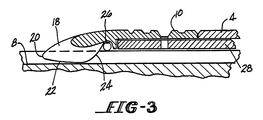
- Fig. 3 the profile of the comb teeth 18 is shown.
- the teeth 18 have a nose portion 20 which dips into the tread grooves 8, and a downwardly tapered bottom edge 22 which sweeps down almost to the bottom of the tread grooves 8.
- the bottom surface 22 rises sharply at an incline 24 distal of the nose 20 and forms a notch 26 adjacent to the base plate 28 to which the comb plate 10 is secured.
- the notches 26 on the teeth 18 are all aligned to define a transverse tunnel which spans the full width of the comb plate 10. As shown in Fig.
- a photo detector 30 is mounted on the outside surface of one of the side skirts 12, and a light source 32 is mounted on the outside surface of the opposite skirt 13. There are apertures cut in the skirts 12 and 13 so that a beam of light can be projected from the light source 32 to the photo detector 30.
- the light source 32 and photo detector 30 are positioned at opposite ends of the tunnel formed by the aligned notches 26 in the comb teeth 18 so that anything passing beneath the comb plate 10 which is bulky enough to intrude into the tunnel will block the beam of light. Fine debris which passes beneath the comb plate 10 will not, however, interrupt the light beam.
- the detector 30 is the type which generates an electrical current when the light beam is interrupted.
- the detector 30 is connected to a signal amplifier 34 which in turn is connected to a relay 36.
- the amplifier strengthens the signal from the detector 30 and the transmits the strengthened signal to the relay 36.
- the relay 36 has a built in delay of about one half second or so, so that the device will not be tripped by passage of irrelevant debris across the tunnel, such as bits of paper, or the like, which are able to get past the comb teeth 18. If the relay 36 stays energized for more than the prescribed time, then it deenergizes the motor 38 and concurrently deenergizes the coil on the brake 40, actuating the latter, whereby the escalator stops. An alarm can also be made to sound if so desired.
- the safety device of this invention can be readily installed in existing escalators merely by retrofitting the old comb plate with a new comb plate modified to provide the tunnel.
- the side skirts can be drilled and the photo sensing assembly can be put in place.
- the device is dependable and well protected against damage or degradation. It will operate consistently regardless of where passengers are standing on the escalator. Adjustments can be made to increase or shorten the time delay responsive to operating conditions for the particular escalators in question.
Landscapes
- Escalators And Moving Walkways (AREA)
Applications Claiming Priority (2)
| Application Number | Priority Date | Filing Date | Title |
|---|---|---|---|
| US146747 | 1988-01-21 | ||
| US07/146,747 US4800998A (en) | 1988-01-21 | 1988-01-21 | Escalator comb safety device |
Publications (1)
| Publication Number | Publication Date |
|---|---|
| EP0325293A1 true EP0325293A1 (de) | 1989-07-26 |
Family
ID=22518830
Family Applications (1)
| Application Number | Title | Priority Date | Filing Date |
|---|---|---|---|
| EP89101013A Withdrawn EP0325293A1 (de) | 1988-01-21 | 1989-01-20 | Sicherheitsvorrichtung für Fahrtreppenkammplatte |
Country Status (5)
| Country | Link |
|---|---|
| US (1) | US4800998A (de) |
| EP (1) | EP0325293A1 (de) |
| JP (1) | JPH01288596A (de) |
| AU (1) | AU2858889A (de) |
| FI (1) | FI890308A7 (de) |
Cited By (2)
| Publication number | Priority date | Publication date | Assignee | Title |
|---|---|---|---|---|
| EP0801021A3 (de) * | 1996-04-10 | 1998-04-29 | Otis Elevator Company | Schutzvorrichtung für Personenbeförderer |
| US6520310B1 (en) | 2001-12-27 | 2003-02-18 | Inventio Ag | Combplate load and obstruction sensor apparatus |
Families Citing this family (34)
| Publication number | Priority date | Publication date | Assignee | Title |
|---|---|---|---|---|
| US5001459A (en) * | 1990-05-23 | 1991-03-19 | Otis Elevator Company | Escalator handrail guard warning device |
| US5370213A (en) * | 1993-07-15 | 1994-12-06 | Otis Elevator Company | Combplate with a wear resistant coating |
| US5372231A (en) * | 1993-12-23 | 1994-12-13 | Otis Elevator Company | Combplate for a people moving device |
| US5361887A (en) * | 1994-03-14 | 1994-11-08 | Otis Elevator Company | Apparatus for detecting an irregularity in the frequency of steps passing a particular point within a passenger conveying device |
| MY114579A (en) * | 1995-04-24 | 2002-11-30 | Inventio Ag | Safety equipment for passenger conveying plants |
| AUPN605295A0 (en) * | 1995-10-18 | 1995-11-09 | Loderway Pty. Limited | Systems for the conveyance of standing passengers |
| US6601688B1 (en) * | 1999-10-21 | 2003-08-05 | Otis Elevator Company | Passenger conveyor gap monitoring device |
| US6976571B2 (en) * | 2000-07-31 | 2005-12-20 | Otis Elevator Company | Comb plate for people mover |
| DE10037172B4 (de) * | 2000-07-31 | 2007-10-04 | Otis Elevator Co., Farmington | Kammplatte für Personenbeförderer |
| JP4191142B2 (ja) * | 2003-02-07 | 2008-12-03 | オーチス エレベータ カンパニー | 移動フランジを備える乗客用コンベアのコムプレート |
| US7334672B2 (en) * | 2005-08-12 | 2008-02-26 | Motor Drives & Controls, Inc. | Method for detecting faults in a combplate and sensor combplate |
| US7648020B2 (en) * | 2008-03-03 | 2010-01-19 | International Business Machines Corporation | Transition plate position sensor for safe check-out counter conveyor operation |
| US9416478B2 (en) | 2009-03-31 | 2016-08-16 | Lg Electronics Inc. | Washing machine and washing method |
| US8966944B2 (en) | 2008-08-01 | 2015-03-03 | Lg Electronics Inc. | Control method of a laundry machine |
| US8746015B2 (en) | 2008-08-01 | 2014-06-10 | Lg Electronics Inc. | Laundry machine |
| US8725458B2 (en) * | 2008-12-30 | 2014-05-13 | International Business Machines Corporation | Heat sink blockage detector |
| EP3103909B1 (de) | 2009-02-11 | 2017-08-16 | Lg Electronics Inc. | Waschmaschine |
| US9234307B2 (en) | 2009-07-27 | 2016-01-12 | Lg Electronics Inc. | Control method of a laundry machine |
| US9822473B2 (en) | 2009-07-27 | 2017-11-21 | Lg Electronics Inc. | Control method of a laundry machine |
| US9695537B2 (en) | 2009-07-27 | 2017-07-04 | Lg Electronics Inc. | Control method of a laundry machine |
| US10533275B2 (en) | 2009-07-27 | 2020-01-14 | Lg Electronics Inc. | Control method of a laundry machine |
| US8776297B2 (en) | 2009-10-13 | 2014-07-15 | Lg Electronics Inc. | Laundry treating apparatus and method |
| US9045853B2 (en) | 2009-10-13 | 2015-06-02 | Lg Electronics Inc. | Laundry treating apparatus |
| DE112013003675A5 (de) * | 2012-07-24 | 2015-04-16 | Thyssenkrupp Fahrtreppen Gmbh | Fahrtreppe oder Fahrsteig mit Sicherheitseinrichtung |
| US9560853B2 (en) * | 2014-12-23 | 2017-02-07 | Aleksandr Taslagyan | Return flow conveyor device for heating food items |
| EP3088346A1 (de) | 2015-04-27 | 2016-11-02 | Thyssenkrupp Elevator Innovation Center, S.A. | Sicherheitsvorrichtung und verfahren zur verhütung von unfällen im kammplattenbereich von fahrtreppen oder fahrsteigen |
| CN107662875B (zh) | 2016-07-29 | 2021-07-06 | 奥的斯电梯公司 | 乘客运输机的梯级与梳齿板的啮合状态监检测 |
| CN106167226A (zh) * | 2016-08-12 | 2016-11-30 | 太仓市微贯机电有限公司 | 一种扶梯梳齿防护装置 |
| JP6606042B2 (ja) * | 2016-09-27 | 2019-11-13 | 株式会社日立製作所 | 乗客コンベア、乗客コンベアの異常検出装置、及び乗客コンベアの異常検出方法 |
| EP3473579A1 (de) * | 2017-10-18 | 2019-04-24 | Otis Elevator Company | Kammplatte und personenförderanlage |
| JP7053383B6 (ja) * | 2018-06-19 | 2022-06-14 | 三菱電機ビルソリューションズ株式会社 | 乗客コンベアの制御装置 |
| WO2020136513A1 (en) * | 2018-12-24 | 2020-07-02 | Mtr Corporation Limited | Detecting object on escalator or moving walkway |
| US20250042699A1 (en) * | 2023-08-02 | 2025-02-06 | Otis Elevator Company | Escalator entrapment detection system |
| US12637331B2 (en) * | 2023-08-14 | 2026-05-26 | Otis Elevator Company | Escalator combplate retraction device |
Citations (2)
| Publication number | Priority date | Publication date | Assignee | Title |
|---|---|---|---|---|
| DE680847C (de) * | 1936-07-07 | 1939-09-09 | Friedrich Goltze | Fahrtreppe |
| AT174817B (de) * | 1951-05-18 | 1953-05-11 | Wertheim Werke Ag | Sicherheitsvorrichtung an Fahrtreppen |
Family Cites Families (7)
| Publication number | Priority date | Publication date | Assignee | Title |
|---|---|---|---|---|
| CH374169A (de) * | 1959-11-09 | 1963-12-31 | Inventio Ag | Vorrichtung zum Stillsetzen von Fahrtreppen, Personen- und Lasten-Bandförderern |
| US3233717A (en) * | 1963-04-05 | 1966-02-08 | Hitachi Ltd | Safety device for escalators |
| JPS49112383A (de) * | 1973-03-02 | 1974-10-25 | ||
| US3913723A (en) * | 1973-07-09 | 1975-10-21 | Westmont Ind | Safety switching for passenger conveyor |
| GB1545772A (en) * | 1975-06-24 | 1979-05-16 | Dunlop Ltd | Comb plates for passenger conveyors |
| JPS61169491A (ja) * | 1985-01-22 | 1986-07-31 | 三菱電機株式会社 | エスカレ−タの安全装置 |
| JPS63272772A (ja) * | 1987-04-30 | 1988-11-10 | 株式会社東芝 | エスカレ−タの乗降口安全装置 |
-
1988
- 1988-01-21 US US07/146,747 patent/US4800998A/en not_active Expired - Fee Related
-
1989
- 1989-01-18 AU AU28588/89A patent/AU2858889A/en not_active Abandoned
- 1989-01-20 FI FI890308A patent/FI890308A7/fi not_active Application Discontinuation
- 1989-01-20 EP EP89101013A patent/EP0325293A1/de not_active Withdrawn
- 1989-01-21 JP JP1012999A patent/JPH01288596A/ja active Pending
Patent Citations (2)
| Publication number | Priority date | Publication date | Assignee | Title |
|---|---|---|---|---|
| DE680847C (de) * | 1936-07-07 | 1939-09-09 | Friedrich Goltze | Fahrtreppe |
| AT174817B (de) * | 1951-05-18 | 1953-05-11 | Wertheim Werke Ag | Sicherheitsvorrichtung an Fahrtreppen |
Cited By (2)
| Publication number | Priority date | Publication date | Assignee | Title |
|---|---|---|---|---|
| EP0801021A3 (de) * | 1996-04-10 | 1998-04-29 | Otis Elevator Company | Schutzvorrichtung für Personenbeförderer |
| US6520310B1 (en) | 2001-12-27 | 2003-02-18 | Inventio Ag | Combplate load and obstruction sensor apparatus |
Also Published As
| Publication number | Publication date |
|---|---|
| FI890308L (fi) | 1989-07-22 |
| FI890308A7 (fi) | 1989-07-22 |
| FI890308A0 (fi) | 1989-01-20 |
| AU2858889A (en) | 1989-08-17 |
| US4800998A (en) | 1989-01-31 |
| JPH01288596A (ja) | 1989-11-20 |
Similar Documents
| Publication | Publication Date | Title |
|---|---|---|
| US4800998A (en) | Escalator comb safety device | |
| US6334522B2 (en) | Control apparatus for passenger conveyor and passenger detecting device | |
| US5923005A (en) | Equipment for approach area monitoring for escalator and travelling walkways | |
| EP0599452B1 (de) | Erfassung fehlender Stufen einer Rolltreppe | |
| US3913723A (en) | Safety switching for passenger conveyor | |
| EP0750585B1 (de) | Vorrichtung zur frequenzunregelmassigkeitsdetektion von stufen, die an einer besonderen stelle einer personenforderanlage vorbeifahren | |
| CA1041933A (en) | Passenger conveyors | |
| US5718319A (en) | Escalator and moving walk comb safety device | |
| EP0801021A2 (de) | Schutzvorrichtung für Personenbeförderer | |
| US11254545B2 (en) | Passenger detection system and method for a passenger moving system | |
| JP4865237B2 (ja) | 乗客コンベア | |
| JPH02300089A (ja) | マンコンベアの安全装置 | |
| CN118529584A (zh) | 安全保护装置及扶梯 | |
| KR101121896B1 (ko) | 안전사고 방지기능을 가지는 에스컬레이터 | |
| JPH04354791A (ja) | マンコンベアの安全装置 | |
| CA1121298A (en) | Transportation apparatus | |
| JP3296395B2 (ja) | マンコンベア | |
| JPH01226692A (ja) | エスカレータ或いは動く歩道の安全装置 | |
| JPS6122940Y2 (de) | ||
| JPS63300091A (ja) | エスカレ−タの安全装置 | |
| JP4835211B2 (ja) | 乗客コンベア | |
| JP2004051293A (ja) | 乗客コンベアの運転装置 | |
| JPH04371487A (ja) | エスカレーターの制御装置 | |
| JPH1143279A (ja) | 乗客コンベヤーの異物検出装置 | |
| JPH0192193A (ja) | エスカレータの安全装置 |
Legal Events
| Date | Code | Title | Description |
|---|---|---|---|
| PUAI | Public reference made under article 153(3) epc to a published international application that has entered the european phase |
Free format text: ORIGINAL CODE: 0009012 |
|
| AK | Designated contracting states |
Kind code of ref document: A1 Designated state(s): CH DE ES FR GB IT LI |
|
| STAA | Information on the status of an ep patent application or granted ep patent |
Free format text: STATUS: THE APPLICATION IS DEEMED TO BE WITHDRAWN |
|
| 18D | Application deemed to be withdrawn |
Effective date: 19900127 |