EP0325295B1 - Automatische Querspleisseinrichtung für unvulkanisierte Elastomerfolien - Google Patents
Automatische Querspleisseinrichtung für unvulkanisierte Elastomerfolien Download PDFInfo
- Publication number
- EP0325295B1 EP0325295B1 EP89101020A EP89101020A EP0325295B1 EP 0325295 B1 EP0325295 B1 EP 0325295B1 EP 89101020 A EP89101020 A EP 89101020A EP 89101020 A EP89101020 A EP 89101020A EP 0325295 B1 EP0325295 B1 EP 0325295B1
- Authority
- EP
- European Patent Office
- Prior art keywords
- blades
- splicing
- supporting surface
- pack
- supporting
- Prior art date
- Legal status (The legal status is an assumption and is not a legal conclusion. Google has not performed a legal analysis and makes no representation as to the accuracy of the status listed.)
- Expired - Lifetime
Links
- 239000000463 material Substances 0.000 title claims description 17
- 238000006073 displacement reaction Methods 0.000 claims description 5
- 230000000750 progressive effect Effects 0.000 claims description 2
- 238000013016 damping Methods 0.000 claims 1
- 230000006835 compression Effects 0.000 description 2
- 238000007906 compression Methods 0.000 description 2
- 239000013536 elastomeric material Substances 0.000 description 2
- 239000000853 adhesive Substances 0.000 description 1
- 230000001070 adhesive effect Effects 0.000 description 1
- 230000000694 effects Effects 0.000 description 1
- 238000004519 manufacturing process Methods 0.000 description 1
- 239000002184 metal Substances 0.000 description 1
- 230000000284 resting effect Effects 0.000 description 1
- 125000006850 spacer group Chemical group 0.000 description 1
Images



Classifications
-
- B—PERFORMING OPERATIONS; TRANSPORTING
- B29—WORKING OF PLASTICS; WORKING OF SUBSTANCES IN A PLASTIC STATE IN GENERAL
- B29D—PRODUCING PARTICULAR ARTICLES FROM PLASTICS OR FROM SUBSTANCES IN A PLASTIC STATE
- B29D30/00—Producing pneumatic or solid tyres or parts thereof
- B29D30/06—Pneumatic tyres or parts thereof (e.g. produced by casting, moulding, compression moulding, injection moulding, centrifugal casting)
- B29D30/38—Textile inserts, e.g. cord or canvas layers, for tyres; Treatment of inserts prior to building the tyre
- B29D30/42—Endless textile bands without bead-rings
-
- B—PERFORMING OPERATIONS; TRANSPORTING
- B29—WORKING OF PLASTICS; WORKING OF SUBSTANCES IN A PLASTIC STATE IN GENERAL
- B29C—SHAPING OR JOINING OF PLASTICS; SHAPING OF MATERIAL IN A PLASTIC STATE, NOT OTHERWISE PROVIDED FOR; AFTER-TREATMENT OF THE SHAPED PRODUCTS, e.g. REPAIRING
- B29C65/00—Joining or sealing of preformed parts, e.g. welding of plastics materials; Apparatus therefor
-
- B—PERFORMING OPERATIONS; TRANSPORTING
- B29—WORKING OF PLASTICS; WORKING OF SUBSTANCES IN A PLASTIC STATE IN GENERAL
- B29C—SHAPING OR JOINING OF PLASTICS; SHAPING OF MATERIAL IN A PLASTIC STATE, NOT OTHERWISE PROVIDED FOR; AFTER-TREATMENT OF THE SHAPED PRODUCTS, e.g. REPAIRING
- B29C66/00—General aspects of processes or apparatus for joining preformed parts
- B29C66/01—General aspects dealing with the joint area or with the area to be joined
- B29C66/05—Particular design of joint configurations
- B29C66/10—Particular design of joint configurations particular design of the joint cross-sections
- B29C66/11—Joint cross-sections comprising a single joint-segment, i.e. one of the parts to be joined comprising a single joint-segment in the joint cross-section
- B29C66/114—Single butt joints
- B29C66/1142—Single butt to butt joints
-
- B—PERFORMING OPERATIONS; TRANSPORTING
- B29—WORKING OF PLASTICS; WORKING OF SUBSTANCES IN A PLASTIC STATE IN GENERAL
- B29C—SHAPING OR JOINING OF PLASTICS; SHAPING OF MATERIAL IN A PLASTIC STATE, NOT OTHERWISE PROVIDED FOR; AFTER-TREATMENT OF THE SHAPED PRODUCTS, e.g. REPAIRING
- B29C66/00—General aspects of processes or apparatus for joining preformed parts
- B29C66/01—General aspects dealing with the joint area or with the area to be joined
- B29C66/05—Particular design of joint configurations
- B29C66/10—Particular design of joint configurations particular design of the joint cross-sections
- B29C66/11—Joint cross-sections comprising a single joint-segment, i.e. one of the parts to be joined comprising a single joint-segment in the joint cross-section
- B29C66/116—Single bevelled joints, i.e. one of the parts to be joined being bevelled in the joint area
- B29C66/1162—Single bevel to bevel joints, e.g. mitre joints
-
- B—PERFORMING OPERATIONS; TRANSPORTING
- B29—WORKING OF PLASTICS; WORKING OF SUBSTANCES IN A PLASTIC STATE IN GENERAL
- B29C—SHAPING OR JOINING OF PLASTICS; SHAPING OF MATERIAL IN A PLASTIC STATE, NOT OTHERWISE PROVIDED FOR; AFTER-TREATMENT OF THE SHAPED PRODUCTS, e.g. REPAIRING
- B29C66/00—General aspects of processes or apparatus for joining preformed parts
- B29C66/40—General aspects of joining substantially flat articles, e.g. plates, sheets or web-like materials; Making flat seams in tubular or hollow articles; Joining single elements to substantially flat surfaces
- B29C66/41—Joining substantially flat articles ; Making flat seams in tubular or hollow articles
- B29C66/43—Joining a relatively small portion of the surface of said articles
-
- B—PERFORMING OPERATIONS; TRANSPORTING
- B29—WORKING OF PLASTICS; WORKING OF SUBSTANCES IN A PLASTIC STATE IN GENERAL
- B29C—SHAPING OR JOINING OF PLASTICS; SHAPING OF MATERIAL IN A PLASTIC STATE, NOT OTHERWISE PROVIDED FOR; AFTER-TREATMENT OF THE SHAPED PRODUCTS, e.g. REPAIRING
- B29C66/00—General aspects of processes or apparatus for joining preformed parts
- B29C66/70—General aspects of processes or apparatus for joining preformed parts characterised by the composition, physical properties or the structure of the material of the parts to be joined; Joining with non-plastics material
- B29C66/71—General aspects of processes or apparatus for joining preformed parts characterised by the composition, physical properties or the structure of the material of the parts to be joined; Joining with non-plastics material characterised by the composition of the plastics material of the parts to be joined
-
- B—PERFORMING OPERATIONS; TRANSPORTING
- B29—WORKING OF PLASTICS; WORKING OF SUBSTANCES IN A PLASTIC STATE IN GENERAL
- B29C—SHAPING OR JOINING OF PLASTICS; SHAPING OF MATERIAL IN A PLASTIC STATE, NOT OTHERWISE PROVIDED FOR; AFTER-TREATMENT OF THE SHAPED PRODUCTS, e.g. REPAIRING
- B29C66/00—General aspects of processes or apparatus for joining preformed parts
- B29C66/80—General aspects of machine operations or constructions and parts thereof
- B29C66/81—General aspects of the pressing elements, i.e. the elements applying pressure on the parts to be joined in the area to be joined, e.g. the welding jaws or clamps
- B29C66/814—General aspects of the pressing elements, i.e. the elements applying pressure on the parts to be joined in the area to be joined, e.g. the welding jaws or clamps characterised by the design of the pressing elements, e.g. of the welding jaws or clamps
- B29C66/8145—General aspects of the pressing elements, i.e. the elements applying pressure on the parts to be joined in the area to be joined, e.g. the welding jaws or clamps characterised by the design of the pressing elements, e.g. of the welding jaws or clamps characterised by the constructional aspects of the pressing elements, e.g. of the welding jaws or clamps
- B29C66/81461—General aspects of the pressing elements, i.e. the elements applying pressure on the parts to be joined in the area to be joined, e.g. the welding jaws or clamps characterised by the design of the pressing elements, e.g. of the welding jaws or clamps characterised by the constructional aspects of the pressing elements, e.g. of the welding jaws or clamps being multi-lamellar or segmented, i.e. comprising a plurality of strips, plates or stacked elements
-
- B—PERFORMING OPERATIONS; TRANSPORTING
- B29—WORKING OF PLASTICS; WORKING OF SUBSTANCES IN A PLASTIC STATE IN GENERAL
- B29C—SHAPING OR JOINING OF PLASTICS; SHAPING OF MATERIAL IN A PLASTIC STATE, NOT OTHERWISE PROVIDED FOR; AFTER-TREATMENT OF THE SHAPED PRODUCTS, e.g. REPAIRING
- B29C66/00—General aspects of processes or apparatus for joining preformed parts
- B29C66/40—General aspects of joining substantially flat articles, e.g. plates, sheets or web-like materials; Making flat seams in tubular or hollow articles; Joining single elements to substantially flat surfaces
- B29C66/41—Joining substantially flat articles ; Making flat seams in tubular or hollow articles
- B29C66/43—Joining a relatively small portion of the surface of said articles
- B29C66/432—Joining a relatively small portion of the surface of said articles for making tubular articles or closed loops, e.g. by joining several sheets ; for making hollow articles or hollow preforms
- B29C66/4324—Joining a relatively small portion of the surface of said articles for making tubular articles or closed loops, e.g. by joining several sheets ; for making hollow articles or hollow preforms for making closed loops, e.g. belts
-
- B—PERFORMING OPERATIONS; TRANSPORTING
- B29—WORKING OF PLASTICS; WORKING OF SUBSTANCES IN A PLASTIC STATE IN GENERAL
- B29C—SHAPING OR JOINING OF PLASTICS; SHAPING OF MATERIAL IN A PLASTIC STATE, NOT OTHERWISE PROVIDED FOR; AFTER-TREATMENT OF THE SHAPED PRODUCTS, e.g. REPAIRING
- B29C66/00—General aspects of processes or apparatus for joining preformed parts
- B29C66/80—General aspects of machine operations or constructions and parts thereof
- B29C66/81—General aspects of the pressing elements, i.e. the elements applying pressure on the parts to be joined in the area to be joined, e.g. the welding jaws or clamps
- B29C66/812—General aspects of the pressing elements, i.e. the elements applying pressure on the parts to be joined in the area to be joined, e.g. the welding jaws or clamps characterised by the composition, by the structure, by the intensive physical properties or by the optical properties of the material constituting the pressing elements, e.g. constituting the welding jaws or clamps
- B29C66/8126—General aspects of the pressing elements, i.e. the elements applying pressure on the parts to be joined in the area to be joined, e.g. the welding jaws or clamps characterised by the composition, by the structure, by the intensive physical properties or by the optical properties of the material constituting the pressing elements, e.g. constituting the welding jaws or clamps characterised by the intensive physical properties or by the optical properties of the material constituting the pressing elements, e.g. constituting the welding jaws or clamps
- B29C66/81265—Surface properties, e.g. surface roughness or rugosity
-
- B—PERFORMING OPERATIONS; TRANSPORTING
- B29—WORKING OF PLASTICS; WORKING OF SUBSTANCES IN A PLASTIC STATE IN GENERAL
- B29K—INDEXING SCHEME ASSOCIATED WITH SUBCLASSES B29B, B29C OR B29D, RELATING TO MOULDING MATERIALS OR TO MATERIALS FOR MOULDS, REINFORCEMENTS, FILLERS OR PREFORMED PARTS, e.g. INSERTS
- B29K2105/00—Condition, form or state of moulded material or of the material to be shaped
- B29K2105/24—Condition, form or state of moulded material or of the material to be shaped crosslinked or vulcanised
- B29K2105/246—Uncured, e.g. green
Definitions
- the present invention relates to an automatic transverse splicing device for green elastomeric sheet material.
- the device according to the present invention may be used to advantage for splicing strips of elastomeric sheet material, particularly relatively thick strips for manufacturing tires, along a transverse slicing line, and is substantially of the type disclosed in US-A-2955640, i. e.
- a number of blades arranged, in use, substantially perpendicular to, and facing a supporting surface for the material to be spliced and a splicing line, and grouped together, in axially-sliding manner to and from the supporting surface, into a deformable pack extending along the splicing line and having a first lateral surface facing the supporting surface; approaching means for enabling, in use, relative displacement of the pack and the supporting surface to and from an operative position wherein the material to be spliced is gripped between the pack and the supporting surface; and pressure means cooperating, in use, with a second surface of the pack opposite to said first surface for axially thrusting the blades towards the supporting surface.
- the standard practice consists in forming opposed conjugate bevels along the two splice edges, which are then brought together and compressed mechanically.
- an automatic device for splicing green elastomeric sheet material along a predetermined transverse splicing line the device being designed to cooperate with a surface supporting said material, and comprising a number of blades arranged, in use, substantially perpendicular to, and facing the supporting surface and the splicing line, and grouped together, in axially-sliding manner to and from the supporting surface, into a deformable pack extending along the splicing line and having a first lateral surface facing the supporting surface; approaching means for enabling, in use, relative displacement of the pack and the supporting surface to and from an operative position wherein the material to be spliced is gripped between the pack and the supporting surface; and pressure means cooperating, in use, with a second surface of the pack opposite to said first surface for axially thrusting the blades towards the supporting surface, characterised by the fact that the pressure means are progressive pressure applying means for successively applying a predetermined axial pressure on to the blades; each blade having a
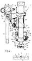
- Number 1 in Fig.s 2 and 3 indicates a supporting surface for strips 2 and 3 of elastomeric material, substantially aligned perpendicular to the Fig.1 plane.
- Strips 2 and 3 present respective opposed transverse edges defined by respective conjugate beveled surfaces 4 and 5 contacting along a transverse splicing line 6.
- an automatic transverse splicing device 7 comprising a crosspiece 8 having a substantially L-shaped section and extending parallel with line 6.
- the said crosspiece 8 consists of a horizontal plate 9 and a front vertical core 10, and is supported in projecting manner, in the Fig.1 position, by an end pillar 11 connected to core 10 by a horizontal bar 12 (Fig.s 2 and 3) integral with the top of pillar 11 and connected to the same by a diagonal brace 13 extending between the mid point of bar 12 and crosspiece 8 and the mid point of pillar 11.
- the said plate 9 presents a support 14 connected in rotary manner to a respective end of a screw 15 turned by a geared motor 16 supported on bracket 12, and housed inside a casing 17 extending between supports 14.
- screw 15 is connected to a nut screw 18 having a horizontal axial appendix 19 coming out of casing 17 through an axial slot 20, to which appendix 19 is connected in sliding manner.
- the free end of appendix 19 presents a pin engaging in sliding manner a vertical slot 21 (Fig. 3) formed on the top end of a vertical plate 22 parallel with core 10.
- Plate 22 constitutes a first arm of an L-shaped bracket 23, the second arm of which is formed by a plate 24 extending parallel with plate 9 from the bottom end of plate 22.
- Bracket 23 forms part of a carriage 25 also comprisng two pairs of rollers 26, each mounted for rotation on a bolt 27 fitted through plate 22.
- Each roller 26 presents an intermediate annular groove 28, and the rollers in each pair of rollers 26 are arranged on opposite sides of a blade 29 lying in a plane parallel with plate 22 and extending substantially over the entire length of core 10 to which blade 29 is connected integral via bolts 30 and via the interposition of spacers 31 (Fig.s 2 and 3).
- Blade 29 presents opposite tapered side edges 32 (Fig. 1) engaging grooves 28 of rollers 26 and forming a fixed slideway for carriage 25.
- a vertical rod 33 constituting the output member of a jack 34 arranged vertically over and integral with plate 24. From the free bottom end of rod 33, there extends axially downwards a threaded appendix 35 engaging a center through hole in a center plate 36 of a fork 37 rendered integral with appendix 35 by two nuts 38.
- the said fork 37 comprises two lateral arms 39 fitted through with a bolt 40 perpendicular to arms 39 and to the Fig. 1 plane.
- a center portion of bolt 40 extending between arms 39 supports in rotary manner a rocker arm 41 designed to turn about the axis of bolt 40 in a plane parallel with the Fig. 1 plane.
- Rocker arm 41 comprises an upper arm 42 hinged, via a pin 43 parallel with bolt 40, to the free end of an output rod 44 of a damper 45 supported in rotary manner by one of arms 39 via pin 46 parallel with pin 43.
- Rocker arm 41 also comprises a lower arm 47, the free end of which consists of a fork 48 comprising two arms 49 fitted through with a bolt 50; the center portion of which bolt supports, as shown particularly in Fig. 4, a splicing roller 51 comprising a cylindrical jacket 52 integral with the outer ring of two bearings 53, the inner ring of which is fitted on to bolt 50.
- a plate 54 projecting from the same side of crosspiece 8 as carriage 25, and connected to the top end of a respective jack 55 having a downward-facing output rod 56.
- Frame 57 comprises two coplanar, aligned, flat rectangular plates 58, the opposite ends of which are connected to rods 56, and the opposed ends of which are connected together by two parallel rods 59 defining a slot 60 engaged by a pack 61 of blades 62 lying in substantially vertical planes and perpendicular to both surface 1 and splicing line 6.
- each blade 62 is substantially rectangular in shape, and presents an intermediate portion having, along each vertical side edge, a recess 63 engaged by a respective rod 59 and defining, on one side, two projecting wings 64 and 65 extending outwards from the respective top and bottom ends of blade 62, and, on the other side, top wing 64 only.
- the width of the said intermediate portion presenting recesses 63 on each blade 62 is at most equal to the width of slot 60, whereas the height of recesses 63 is greater than the thickness of rods 59, so as to enable relatively ample vertical displacement (equal to the difference between the height of recesses 63 and the thickness of rods 59) of blades 62 in relation to frame 57.
- frame 57 presents a supporting foot 66, the bottom end of which is substantially flush with the respective serrated bottom edges 67 of blades 62, when the said blades 62 are arranged with respective wings 64 resting on rods 59.
- frame 57 also presents a gripping device 68 designed to grip blades 62 into a pack 61, while at the same time allowing the said blades 62 to slide vertically in relation to both one another and the said frame 57.
- each pair of adjacent blades 62 comprises a first blade preferably formed from metal, and a second blade formed from a material, e.g. plastic, having a low friction coefficient.
- roller 51 operates selectively and successively on blades 62, by sbjecting each of the same to axial pressure for pressing together the said surfaces 4 and 5.
- each point along splicing line 6 is therefore subjected to localised compression, which is enhanced by the serrated design of respective edges 67 of blades 62, and the effect of which is to merge the elastomeric material of strips 2 and 3, not only perpendicularly in relation to surface 1, but also transversely, thus providing for optimum mechanical grip of surfaces 4 and 5 of strips 2 and 3.
Landscapes
- Engineering & Computer Science (AREA)
- Mechanical Engineering (AREA)
- Textile Engineering (AREA)
- Tyre Moulding (AREA)
- Lining Or Joining Of Plastics Or The Like (AREA)
- Replacement Of Web Rolls (AREA)
Claims (6)
- Automatische Einrichtung (7) zum Querspleissen unvulkanisierter Elastomerfolien entlang einer vorbestimmten querverlaufenden Spleisslinie (6), wobei die Einrichtung (7) ausgelegt ist, um mit einer Fläche (1) zusammenzuarbeiten, die die Folie bzw. das Material trägt und eine Anzahl von Blättern (62) aufweist, die im Gebrauch im wesentlichen senkrecht zur Tragfläche (1) und zur Spleisslinie (6) angeordnet sind und dieser gegenüberliegen und gemeinsam in axial verschiebender Weise und die Tragfläche (1) zu und von ihr weg in einem deformierbaren Paket (61) gruppiert sind, das sich entlang der Spleisslinie (6) erstreckt und eine erste seitliche Fläche besitzt, die der Tragfläche (1) gegenüberliegt, sowie Näherungsmittel (55), die im Gebrauch die relative Verschiebung des Pakets (61) und der Tragfläche (1) in eine Betriebsposition hinein und aus ihr heraus ermöglichen, wobei die zu spleissende Folie/Material zwischen dem Paket (61) und der Tragfläche (1) eingeklemmt wird, und wobei Druckmittel (51) im Gebrauch mit einer zweiten Fläche des Pakets (61), die der ersten Fläche gegenüberliegt, zusammenarbeiten, um die Blätter (62) axial in Richtung auf die Tragfläche (1) zu drücken, dadurch gekennzeichnet, daß die Druckmittel (51) Stufendruck ausübende Mittel sind, um aufeinanderfolgend einen vorbestimmten Axialdruck auf die Blätter (62) auszuüben, wobei jedes Blatt (62) eine Sägezahn-Bodenkante (67) besitzt, die an der genannten ersten Fläche angeordnet ist, um mit der zu spleissenden Folie/Material in Kontakt zu gelangen.
- Einrichtung nach Anspruch 1, dadurch gekennzeichnet, daß die Druckmittel eine Spleisswalze (51) umfassen, die der zweiten Fläche gegenüberliegend angeordnet ist, sowie Führungsmittel (29), die sich parallel zur Spleisslinie (6) erstrecken, Schlitten (25), die die Spleisswalze bzw. -rolle (51) tragen und ausgelegt sind, sich entlang der Führungsmittel (29) zu bewegen, erste Betätigungsmittel (34), die zwischen dem Schlitten (25) und der Spleisswalze (51) angeordnet sind, um die Spleisswalze (51) in eine Betriebsposition hinein- und aus ihr herauszubewegen, wobei sie mit vorbestimmten Druck die zweite Fläche des Pakets (61) berührt und wobei zweite Betätigungsmittel (15, 16, 18) vorgesehen sind, um den Schlitten (25) entlang der Führungsmittel (29) hin- und herzubewegen, so daß die Spleisswalze (51), wenn sie in ihrer Betriebsposition ist, nacheinander auf den Blättern (62) arbeitet und dieselben in Richtung auf die Tragfläche (1) drückt.
- Einrichtung nach Anspruch 1 oder 2, dadurch gekennzeichnet, daß die Nährungsmittel einen Rahmen (57) umfassen, der das Paket (61) an Blätter (62) trägt, und daß ferner Betätigungsmittel (55) vorgesehen sind, um den Rahmen (57) in eine Betriebsposition hinein, in der er die Tragfläche (1) berührt, und aus ihr herauszubewegen, wobei die Blätter (62) mit dem Rahmen (57) in solcher Weise verbunden sind, daß sie in axialer Beziehung zu demselben gleiten.
- Einrichtung nach irgendeinem der vorstehenden Ansprüche, dadurch gekennzeichnet, daß ein Blatt (62) jedes benachbarten Blätterpaares aus einem Material geformt ist, das einen niedrigen Reibungskoeffizienten besitzt.
- Einrichtung nach Anspruch 3 oder 4, dadurch gekennzeichnet, daß der Rahmen (57) zwei Stangen (59) umfaßt, die parallel zueinander und zur Spleisslinie (6) verlaufen, wobei die Stangen (59) einen Schlitz (60) bilden, über den die Blätter (62) in jedem Paket (61) in axial verschiebender Weise bewegen, wobei jedes Blatt (62) einen Zwischenteil bildet, der maximal die gleiche Breite wie der Schlitz (60) besitzt und obere seitliche Flügel (64) zu seinem eigenen Abstützen auf den Stangen (59) aufweist, und wobei die Länge des Zwischenteils größer ist als die Dicke der Stangen (59).
- Einrichtung nach irgendeinem der vorstehenden Ansprüche 2 bis 5, dadurch gekennzeichnet, daß sie einen Schwinghebel (41) umfaßt, der um ein Scharnier (40) senkrecht zur Spleisslinie (6) und parallel zur Tragfläche (1) drehbar ist, und daß der Schwenkpunkt/Scharnier (40) so ausgelegt ist, daß er sich durch das erste Betätigungsmittel (34) auf die Tragfläche (1) zu- und von ihr wegbewegt, und wobei die Walze (51) in drehbarer Weise durch einen ersten Arm (47) auf dem Schwinghebel (41) gelagert ist und wobei Dämpfungsmittel (45) mit einem zweiten Arm (42) auf dem Schwinghebel (41) verbunden sind, um die Rotation desselben um das Scharnier (40) zu steuern.
Applications Claiming Priority (2)
| Application Number | Priority Date | Filing Date | Title |
|---|---|---|---|
| IT67039/88A IT1218972B (it) | 1988-01-22 | 1988-01-22 | Dispositivo automatico per la giunzione trasversale di materiale elastomerico verde in foglio |
| IT6703988 | 1988-01-22 |
Publications (3)
| Publication Number | Publication Date |
|---|---|
| EP0325295A2 EP0325295A2 (de) | 1989-07-26 |
| EP0325295A3 EP0325295A3 (de) | 1991-07-24 |
| EP0325295B1 true EP0325295B1 (de) | 1995-03-15 |
Family
ID=11299105
Family Applications (1)
| Application Number | Title | Priority Date | Filing Date |
|---|---|---|---|
| EP89101020A Expired - Lifetime EP0325295B1 (de) | 1988-01-22 | 1989-01-20 | Automatische Querspleisseinrichtung für unvulkanisierte Elastomerfolien |
Country Status (7)
| Country | Link |
|---|---|
| US (1) | US4892608A (de) |
| EP (1) | EP0325295B1 (de) |
| JP (1) | JP2603327B2 (de) |
| BR (1) | BR8900262A (de) |
| DE (1) | DE68921649T2 (de) |
| ES (1) | ES2068840T3 (de) |
| IT (1) | IT1218972B (de) |
Cited By (1)
| Publication number | Priority date | Publication date | Assignee | Title |
|---|---|---|---|---|
| EP4494853A1 (de) | 2023-07-16 | 2025-01-22 | Konstrukta - TireTech, s. r. o. | Vorrichtung und verfahren zum aneinanderfügen von enden von elastomeren mischungsstreifen |
Families Citing this family (6)
| Publication number | Priority date | Publication date | Assignee | Title |
|---|---|---|---|---|
| IT1241254B (it) * | 1990-06-08 | 1993-12-29 | Firestone International Developments.P.A. | Dispositivo per la giunzione di materiale autoadesivo in foglio di gomma crusa |
| EP0486721A1 (de) * | 1990-11-22 | 1992-05-27 | PIRELLI COORDINAMENTO PNEUMATICI Società per Azioni | Vorrichtung zum Messen der Überlappung zwischen zwei verbundenen Abschnitten gummierten Gewebes bei der Reifenherstellung |
| DE102004024715B4 (de) * | 2004-05-19 | 2017-06-01 | Continental Reifen Deutschland Gmbh | Spleißvorrichtung |
| US7950285B2 (en) * | 2006-11-10 | 2011-05-31 | Kistler Holding Ag | Pressure sensor for measurements in hot, dynamic processes |
| NL2005819C2 (nl) * | 2010-12-06 | 2012-06-07 | Vmi Holland Bv | Lasinrichting en werkwijze voor het aan elkaar lassen van stroken van rubbermateriaal. |
| NL2027675B1 (en) * | 2021-03-01 | 2022-09-20 | Vmi Holland Bv | Method and splicer for splicing a leading end and a trailing end of a tire component |
Family Cites Families (7)
| Publication number | Priority date | Publication date | Assignee | Title |
|---|---|---|---|---|
| US2409571A (en) * | 1942-04-29 | 1946-10-15 | Goodrich Co B F | Apparatus for splicing rubberlike material |
| US2487149A (en) * | 1947-06-18 | 1949-11-08 | Goodrich Co B F | Apparatus for splicing adhesive sheet material |
| US2955640A (en) * | 1958-08-19 | 1960-10-11 | Goodrich Co B F | Profiled tire tread splicing |
| GB868659A (en) * | 1958-08-19 | 1961-05-25 | Karlsruhe Augsburg Iweka | Apparatus for closing toothpaste-type tubes of plastic material |
| US4722132A (en) * | 1986-05-12 | 1988-02-02 | The Goodyear Tire & Rubber Company | Splicing method for tire sheet material |
| IT1193155B (it) * | 1986-07-16 | 1988-06-02 | Firestone Int Dev Spa | Dispositivo automatico di giuntatura trasversale per l assemblaggio di pneumatici |
| US4808257A (en) * | 1986-10-14 | 1989-02-28 | The Goodyear Tire & Rubber Company | Tread splicer |
-
1988
- 1988-01-22 IT IT67039/88A patent/IT1218972B/it active
-
1989
- 1989-01-20 DE DE68921649T patent/DE68921649T2/de not_active Expired - Fee Related
- 1989-01-20 EP EP89101020A patent/EP0325295B1/de not_active Expired - Lifetime
- 1989-01-20 ES ES89101020T patent/ES2068840T3/es not_active Expired - Lifetime
- 1989-01-21 JP JP1011020A patent/JP2603327B2/ja not_active Expired - Fee Related
- 1989-01-23 US US07/299,589 patent/US4892608A/en not_active Expired - Fee Related
- 1989-01-23 BR BR898900262A patent/BR8900262A/pt not_active IP Right Cessation
Cited By (1)
| Publication number | Priority date | Publication date | Assignee | Title |
|---|---|---|---|---|
| EP4494853A1 (de) | 2023-07-16 | 2025-01-22 | Konstrukta - TireTech, s. r. o. | Vorrichtung und verfahren zum aneinanderfügen von enden von elastomeren mischungsstreifen |
Also Published As
| Publication number | Publication date |
|---|---|
| JPH028141A (ja) | 1990-01-11 |
| US4892608A (en) | 1990-01-09 |
| EP0325295A2 (de) | 1989-07-26 |
| EP0325295A3 (de) | 1991-07-24 |
| DE68921649D1 (de) | 1995-04-20 |
| IT8867039A0 (it) | 1988-01-22 |
| DE68921649T2 (de) | 1995-07-27 |
| IT1218972B (it) | 1990-04-24 |
| JP2603327B2 (ja) | 1997-04-23 |
| ES2068840T3 (es) | 1995-05-01 |
| BR8900262A (pt) | 1989-09-19 |
Similar Documents
| Publication | Publication Date | Title |
|---|---|---|
| KR20220007019A (ko) | 케이블 처리 시스템 | |
| CN108326969B (zh) | 一种板料的横切锯床 | |
| CN116000522B (zh) | 一种板框焊接装置 | |
| US5042633A (en) | Roller bearing device for workpiece transfer platforms | |
| US4892608A (en) | Automatic transverse splicing device for uncured elastomeric sheet material | |
| CN119175401B (zh) | 一种钢带加工装置及系统 | |
| CN112678271A (zh) | 一种具有半自动封口功能的包装纸箱的固定装置 | |
| CN109795902B (zh) | 一种自动冲孔机 | |
| US4189818A (en) | Apparatus and method for the assembly of glass sheets | |
| US3877336A (en) | Blank punching apparatus | |
| JPH07276505A (ja) | シート状材料の突合せ接合装置 | |
| CN118989059B (zh) | 一种配电柜组件折弯加工设备 | |
| CN118003017B (zh) | 一种钢结构焊接成型排布固定夹具 | |
| CN112606050A (zh) | 一种瓦楞纸板再制备处理方法 | |
| CN219729994U (zh) | 一种纸张收卷结构及装置 | |
| CN116944788B (zh) | 一种异型夹持臂的多角度拼焊工装及其应用方法 | |
| CN219745889U (zh) | 一种齿条校直机矫正模块 | |
| EP0253067B1 (de) | Automatische Querverspleissvorrichtung bei Reifenaufbau | |
| US4096907A (en) | Strand withdrawal assembly for continuous casting plants | |
| CN223300957U (zh) | 一种便于输送板材的液压剪板机 | |
| EP0370582B1 (de) | Vorrichtung zum Biegen eines Blechrandes | |
| EP0368686B1 (de) | Automatisierbare Rundwalzeneinrichtung mit verzahnten Walzen | |
| CN114406609A (zh) | 一种板簧的智能生产线 | |
| US4131222A (en) | Snapping of sheets of glass | |
| FI71083B (fi) | Anordning foer skaerning av skivor |
Legal Events
| Date | Code | Title | Description |
|---|---|---|---|
| PUAI | Public reference made under article 153(3) epc to a published international application that has entered the european phase |
Free format text: ORIGINAL CODE: 0009012 |
|
| AK | Designated contracting states |
Kind code of ref document: A2 Designated state(s): DE ES FR GB IT LU |
|
| RAP1 | Party data changed (applicant data changed or rights of an application transferred) |
Owner name: BRIDGESTONE/FIRESTONE, INC. |
|
| PUAL | Search report despatched |
Free format text: ORIGINAL CODE: 0009013 |
|
| AK | Designated contracting states |
Kind code of ref document: A3 Designated state(s): DE ES FR GB IT LU |
|
| 17P | Request for examination filed |
Effective date: 19911231 |
|
| 17Q | First examination report despatched |
Effective date: 19930714 |
|
| GRAA | (expected) grant |
Free format text: ORIGINAL CODE: 0009210 |
|
| AK | Designated contracting states |
Kind code of ref document: B1 Designated state(s): DE ES FR GB IT LU |
|
| REF | Corresponds to: |
Ref document number: 68921649 Country of ref document: DE Date of ref document: 19950420 |
|
| REG | Reference to a national code |
Ref country code: ES Ref legal event code: FG2A Ref document number: 2068840 Country of ref document: ES Kind code of ref document: T3 |
|
| ITF | It: translation for a ep patent filed | ||
| ET | Fr: translation filed | ||
| PGFP | Annual fee paid to national office [announced via postgrant information from national office to epo] |
Ref country code: GB Payment date: 19951218 Year of fee payment: 8 |
|
| PGFP | Annual fee paid to national office [announced via postgrant information from national office to epo] |
Ref country code: FR Payment date: 19960111 Year of fee payment: 8 |
|
| PLBE | No opposition filed within time limit |
Free format text: ORIGINAL CODE: 0009261 |
|
| STAA | Information on the status of an ep patent application or granted ep patent |
Free format text: STATUS: NO OPPOSITION FILED WITHIN TIME LIMIT |
|
| PGFP | Annual fee paid to national office [announced via postgrant information from national office to epo] |
Ref country code: ES Payment date: 19960123 Year of fee payment: 8 |
|
| PGFP | Annual fee paid to national office [announced via postgrant information from national office to epo] |
Ref country code: DE Payment date: 19960125 Year of fee payment: 8 |
|
| PGFP | Annual fee paid to national office [announced via postgrant information from national office to epo] |
Ref country code: LU Payment date: 19960201 Year of fee payment: 8 |
|
| 26N | No opposition filed | ||
| PG25 | Lapsed in a contracting state [announced via postgrant information from national office to epo] |
Ref country code: LU Free format text: LAPSE BECAUSE OF NON-PAYMENT OF DUE FEES Effective date: 19970120 Ref country code: GB Effective date: 19970120 |
|
| PG25 | Lapsed in a contracting state [announced via postgrant information from national office to epo] |
Ref country code: ES Free format text: LAPSE BECAUSE OF NON-PAYMENT OF DUE FEES Effective date: 19970121 |
|
| GBPC | Gb: european patent ceased through non-payment of renewal fee |
Effective date: 19970120 |
|
| PG25 | Lapsed in a contracting state [announced via postgrant information from national office to epo] |
Ref country code: FR Effective date: 19970930 |
|
| PG25 | Lapsed in a contracting state [announced via postgrant information from national office to epo] |
Ref country code: DE Effective date: 19971001 |
|
| REG | Reference to a national code |
Ref country code: FR Ref legal event code: ST |
|
| REG | Reference to a national code |
Ref country code: ES Ref legal event code: FD2A Effective date: 19990201 |
|
| PG25 | Lapsed in a contracting state [announced via postgrant information from national office to epo] |
Ref country code: IT Free format text: LAPSE BECAUSE OF NON-PAYMENT OF DUE FEES;WARNING: LAPSES OF ITALIAN PATENTS WITH EFFECTIVE DATE BEFORE 2007 MAY HAVE OCCURRED AT ANY TIME BEFORE 2007. THE CORRECT EFFECTIVE DATE MAY BE DIFFERENT FROM THE ONE RECORDED. Effective date: 20050120 |