EP0325340A2 - Déphaseur réciproque à ferrite à commutation rapide - Google Patents
Déphaseur réciproque à ferrite à commutation rapide Download PDFInfo
- Publication number
- EP0325340A2 EP0325340A2 EP89300001A EP89300001A EP0325340A2 EP 0325340 A2 EP0325340 A2 EP 0325340A2 EP 89300001 A EP89300001 A EP 89300001A EP 89300001 A EP89300001 A EP 89300001A EP 0325340 A2 EP0325340 A2 EP 0325340A2
- Authority
- EP
- European Patent Office
- Prior art keywords
- phase shifter
- input
- waveguide
- phase
- phase shifters
- Prior art date
- Legal status (The legal status is an assumption and is not a legal conclusion. Google has not performed a legal analysis and makes no representation as to the accuracy of the status listed.)
- Withdrawn
Links
- 229910000859 α-Fe Inorganic materials 0.000 title claims abstract description 37
- 230000010287 polarization Effects 0.000 claims description 49
- 230000001902 propagating effect Effects 0.000 claims description 20
- 230000008878 coupling Effects 0.000 claims description 2
- 238000010168 coupling process Methods 0.000 claims description 2
- 238000005859 coupling reaction Methods 0.000 claims description 2
- 230000005415 magnetization Effects 0.000 abstract description 24
- 230000001934 delay Effects 0.000 abstract description 2
- 230000010363 phase shift Effects 0.000 description 18
- 230000009977 dual effect Effects 0.000 description 9
- 238000003780 insertion Methods 0.000 description 7
- 230000037431 insertion Effects 0.000 description 7
- 238000013461 design Methods 0.000 description 6
- 230000005284 excitation Effects 0.000 description 5
- 230000008859 change Effects 0.000 description 4
- 239000011159 matrix material Substances 0.000 description 4
- 238000000034 method Methods 0.000 description 4
- 238000010276 construction Methods 0.000 description 3
- 230000008569 process Effects 0.000 description 3
- 239000002131 composite material Substances 0.000 description 2
- 238000010586 diagram Methods 0.000 description 2
- 230000005684 electric field Effects 0.000 description 2
- 230000004048 modification Effects 0.000 description 2
- 238000012986 modification Methods 0.000 description 2
- 230000003068 static effect Effects 0.000 description 2
- 238000013459 approach Methods 0.000 description 1
- 230000005540 biological transmission Effects 0.000 description 1
- 239000011248 coating agent Substances 0.000 description 1
- 238000000576 coating method Methods 0.000 description 1
- 239000013256 coordination polymer Substances 0.000 description 1
- 230000000694 effects Effects 0.000 description 1
- 238000005516 engineering process Methods 0.000 description 1
- 239000000463 material Substances 0.000 description 1
- 230000035699 permeability Effects 0.000 description 1
- 238000009738 saturating Methods 0.000 description 1
- 239000004065 semiconductor Substances 0.000 description 1
- 230000035945 sensitivity Effects 0.000 description 1
- 125000006850 spacer group Chemical group 0.000 description 1
- 238000009966 trimming Methods 0.000 description 1
- 238000004804 winding Methods 0.000 description 1
Images








Classifications
-
- H—ELECTRICITY
- H01—ELECTRIC ELEMENTS
- H01P—WAVEGUIDES; RESONATORS, LINES, OR OTHER DEVICES OF THE WAVEGUIDE TYPE
- H01P1/00—Auxiliary devices
- H01P1/18—Phase-shifters
- H01P1/19—Phase-shifters using a ferromagnetic device
Definitions
- This invention relates to ferrite phase shifters. More particularly, the invention relates to a reciprocal ferrite phase shifter that has the capability of rapidly changing states while providing low loss operation at frequencies in the upper microwave range and while handling high peak and average RF power.
- Microwave phase shifters are used in many applications where it is required to electronically control the transmission of microwave energy either within a system (through a microwave switch) or in free space (in an electronically scanned antenna). These phase shifters typically use either semiconductor (diode) or ferrite technology. Both approaches have various advantages with the diodes generally being superior for lower frequency, low power applications and the ferrite version preferred where high power and/or high frequency conditions are experienced. Both broad classes of phase shifters are presently extensively used in microwave and millimeter systems.
- ferrite phase shifters are preferable where high power, low insertion loss (at frequencies as high as X-band), and wide frequency ranges are desired.
- phase shifters which are capable of switching in less than 50 to 100 microseconds, only two ferrite devices are widely used: the reciprocal latching phase shifter (dual-mode) and nonreciprocal twin-slab phase shifter.
- twin-slab phase shifter is extensively used in applications where the system requires extremely rapid reconfiguratlon since this unit is capable of changing its setting within 1 to 10 microseconds (that is, 10 to 100 times as fast as the dual-mode phase shifter).
- the twin-slab phase shifter is, however, inherently a nonreciprocal device and many systems require transmit and receive operations to occur either simultaneously or sequentially within a very short period of time.
- the dual-mode phase shifter is often used since it provides very nearly the same phase shift for both transmit and receive operation without the need for switching (a state change).
- a need exists for a reciprocal phase shifter i.e., one which provides substantially the same phase shift for both transmit and receive operations
- a reciprocal phase shifter i.e., one which provides substantially the same phase shift for both transmit and receive operations
- switching i.e., changing state
- a non-reciprocal phase shifter in order to operate in transmit and receive modes, must be switched between transmit and receive states.
- a phase shifter is set in the transmit state to generate a radar pulse, but must be toggled to the receive state in time to receive the pulse returning from a target. If the pulses are transmitted at a high pulse repetition frequency, such a non-reciprocal phase shifter can't be switched at a fast enough rate to receive the returning pulses.
- the dual mode phase shifter is a reciprocal phase shifter and does not need to be switched between the transmit mode and receive modes, such a phase shifter has significant shortcomings for many radar applications.
- a long time is required to change the position to which the antenna is pointing (relative to a system using twin-slab phase shifters).
- the setting of the phase shifters in the phase array must be changed rapidly.
- Such dual mode phase shifters thus do not perform optimally in antenna systems where it is desired to move the antenna beam very rapidly.
- the excess time required to change the antenna position with dual mode phase shifters limits the functions which the antenna system can perform.
- the phase shifter of the present invention uniquely provides for both reciprocal operation and fast switching speeds. Reciprocal operation in the transmit and receive modes is achieved by employing two latching, toroidal nonreciprocal phase shifters; one for transmitting and one for receiving. Thus, transmit and receive operations may occur simultaneously without the need for switching phase shifter states.
- the exemplary embodiment of the present invention utilizes input and output circulating devices which include a Faraday rotator and septum polarizer for appropriately routing signals through one or the other of the phase shifters depending upon the direction of input signal propogation.
- the phase shifter of the exemplary embodiment of the present invention also achieves fast switching since the latching, toroidal, nonreciprocal phase shifters are transversely magnetized devices and are disposed entirely within a waveguide so that the generated magnetic field is confined entirely within the waveguide.
- the ferrite phase shifting elements do not intersect the waveguide walls and, thus, during a switching operation (e.g., when the toroid magnetization state is changed due to application of the latching magnetizing current pulse), the magnetic field is not switched through conductive waveguide walls. Accordingly, eddy currents are not induced during a switching operation thereby allowing for fast phase changes to be accomplished (which are not limited due to eddy current delays). This configuration allows for switching to occur within a time period in the range of 1 to 10 microseconds.
- the present invention provides a phase shifter structure which has properties heretofor unattainable by any prior art ferrite phase shifter, thereby permitting use in applications where prior art ferrite phase shifters cannot perform adequately.
- the present invention has the advantages of existing ferrite phase shifters (as compared to diode phase shifters, i.e., it provides low loss operation at frequencies in the upper microwave and lower millimeter usage and handles high peak and average RF power).
- phase shifter of the present invention Prior to describing the details of an exemplary embodiment of the phase shifter of the present invention, a brief discussion is provided of both the dual-mode and twin-slab phase shifters for background information.
- a prior art dual-mode reciprocal latching waveguide phase shifter has the configuration shown in Figure 1 and the equivalent circuit of Figure 2. As can be seen in the equivalent circuit, this device achieves reciprocal operation by combining nonreciprocal elements which are represented by phasers 1 and 2 in Figure 2.
- the basic phase shifting element is a longitudinally magnetized (via winding 12), fully filled ferrite-loaded waveguide 3 having, typically, either a round or square cross section. Through this rod 5 propagates a circularly polarized wave. The phase shift which that wave experiences depends upon the magnitude and sense of the longitudinal magnetization.
- the device is made in a "latching" configuration by providing external ferrite return paths 8, 9 outside of the waveguide walls.
- a composite toroid is thus formed consisting of the ferrite rod 5 through which the microwave energy passes and the external magnetic "yokes" which define the return paths 8, 9.
- the waveguide wall 10 which is a thin (perhaps 100 microinches) layer of high conductivity material deposited directly upon the ferrite rod.
- This conducting layer acts as a shorted turn when switching occurs, considerably lengthening the time required for such an operation. In applications where switching speed is of great importance, it is possible to reduce the thickness of the coating below that required for optimum insertion loss and achieve switching times approaching 50 microseconds for X-band phase shifters.
- the central phase shifting section itself is, however, nonreciprocal since the phase shift experienced by a wave of given polarization will depend upon the direction as well as the magnitude of the magnetization (note that a right-hand CP wave propagating from left to right will see a different direction of magnetization from that seen by a wave of the same polarization propagating from right to left).
- the fact that two orthogonal modes of propagation exist within the structure allows reciprocal operation to be achieved if a different sense of polarization is launched when entering the rod 5 from the right than from the left. This is accomplished by the single transversely magnetized non-reciprocal circular polarizers 6, 7 shown at either end of the phase shifting section.
- These polarizers 6, 7 are also sections of fully filled ferrite-loaded waveguide with circular or square cross section, but their magnetic biasing field is transverse (rather than parallel) to the direction of propagation.
- the operation of these elements is similar to that of a conventional dielectric quarter-wave plate in that linear polarization will be converted to circular polarization and vice versa.
- the sense of linear polarization (or circular polarization) launched depends, however, upon the direction of propagation.
- These quarter-wave plates function as the 4-port circulators shown in Figure 2 with the fourth (terminated) port being a resistive vane element 18, 19 at the linear polarized end of the structure oriented to absorb any cross-polarized waves emerging from the unit.
- phase shifting section in conjunction with the external return path, forms a toroidal structure, the unit may be set to a remanant magnetic state and no magnetizing current will be required after this state is reached.
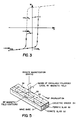
- a saturating current is applied to drive the magnetization of the toroid all the way to the bottom of the loop at -4 ⁇ M max ; when this current pulse is removed, the magnetization falls to the fully remanent value of -4 ⁇ M r .
- a precisely controlled magnetizing current pulse is applied which magnetizes the toroid to Point A in Figure 3 and when this current is removed, the magnetization falls to the minor loop remanent state, 4 ⁇ M b .
- such a switching process allows a continuum of phase states between the maximum values which would be produced at ⁇ 4 ⁇ M r .
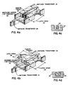
- the ferrite elements 20 and 21 are hollow rectangular cylinders that are placed longitudinally in their respective waveguides 22. Designs using both one and two toroids are common but the dual-toroid design is more common for narrow-band radar applications and for millimeter-wave applications. The single-toroid design has demonstrated the best performance when the requirement is for a frequency independent phase shift over bandwidths exceeding one octave.
- Each of the phase shifters includes matching transformers 24, 25 and latching wires 26.
- the dual-toroid shown in Figure 4b includes a dielectric slab 34 between each toroid 21 and a pair of latching wires 26 associated with each toroid.
- the latching fields for toroids 20 and 21 are shown in Figures 4c and 4d, respectively.
- the configuration of a generic, twin-slab phase shifter consists of two magnetized ferrite slabs 30, 32 that are separated by a thin dielectric spacer 34 in the center of the waveguide 31.
- the ferrite slabs 30, 32 are magnetized by a static magnetic field that is directed up in one slab and down in the other as shown by the arrows associated therewith.
- This static bias field may be produced by external magnets, or from "permanent" magnetization of the ferrite.
- the RF magnetic field associated with the propagating microwave signal is oriented such that the field lines form loops 36, 38, 40 that lie parallel to the broad wall of the waveguide 31. These "loops" 36, 38, 40 move along the waveguide 31 as the signal propagates.
- the microwave signal has the maximum possible sensitivity to the permeability of the ferrite. Therefore, a propagation constant of the microwave signal can be controlled by changing the magnetization of the ferrite.
- Figure 6 shows three arrangements for controlling the magnetization of the ferrite.
- the permanent magnets 50, 52 shown in Figure 6(a) which magnetize ferrite slabs 54 are separated by dielectric 56 and are useful for making fixed phase shifters, such as might be used in four-port circulators.
- the single- and dual-toroid phase shifters can be "latched" to partially or fully magnetized conditions by passing current pulses 60, 62 through the center of the toroids as shown in Figures 6(b) and 6(c).
- twin-slab phase shifter is inherently nonreciprocal since circular polarization of the RF magnetic field is reversed if the direction of microwave propagation is reversed. "Switched" reciprocal operation can, however, be achieved if the magnetization of the toroidal element is exactly reversed prior to the time at which the reverse propagating signal is applied.
- the dual toroids shown in Figure 6(c) are separated by a dielectric slab 68 and the single toroid 64 shown in 6(b) includes a dielectric core 69.
- Varying the phase shift produced may be accomplished in the same manner as with the dual-mode phase shifter, i.e., by varying the minor loop state of remanent magnetization to which the toroidal phase shifting element is magnetized.
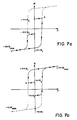
- This process is illustrated in Figures 7a and 7b.
- a two-step switching operation is required with the magnetization first being set into a fully magnetized remanent state at one end of the loop and then to a precisely controlled minor loop remanent state corresponding to the desired phase shift.
- Figure 7(b) shows the switching operation if switched reciprocity is to be achieved for a reverse propagating signal. As can be seen, the direction of the "reset" and “set” switching operations are exactly reversed from those illustrated in 7(a) for forward propagation.
- FIG. 8 shows the variation of insertion phase with magnetization for a typical twin-slab phase shifter. Curves are presented for both transmit and receive operation in order to further illustrate the concept of "switched" reciprocity. As shown in Figure 8, as the magnetization is varied from fully magnetized in one direction to fully magnetized in the opposite direction a continuous range of phase states is achieved between maximum and minimum values.
- a second technique in addition to varying the minor loop remnant states may be used for producing multiple states of phase shift with the twin-slab phase shifter.
- a number of cascaded phase shifting elements are employed each having its own phase shifting toroid(s) 80-83.
- Toroid element 83 provides 180° phase shift.
- Each succeeding element 82, 81, 80 provides one half the phase shift of its neighbor (i.e., 90°, 45°, 22.5°).
- each toroid is latched via pulse generators 85a-d and associated amplifiers 87a-d in one direction or the other only to its fully magnetized remanent states ( ⁇ 4 ⁇ M r ).
- phase shift (quantized to the number of phase shifting sections or "bits" employed) may be obtained by varying the number of command input bits 89 which are set or reset.
- pseudoreciprocal operation can be achieved if each phase shifting bit is set to the opposite state of remanent magnetization prior to the arrival of the reversed propagating signal.
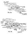
- FIG. 10a and 10b A general realization of an exemplary embodiment of the fast-switching, pseudoreciprocal phase shifter of the present invention is illustrated in Figures 10a and 10b. As can be seen, this unit is comprised of two twin-slab nonreciprocal phase shifters 100, 102, two septum polarizers 104, 106, two Faraday rotators 108, 110, and two absorptive vane polarization selectors 112, 114.
- An equivalent circuit of this device is shown in Figure 11. Although the equivalent circuit is represented as being similar to that of the dual-mode phase shifter which was presented earlier in Figure 2, the exemplary embodiment is significantly different from the dual-mode phase shifter.
- phase shifters 100, 102 employed in the exemplary embodiment which share common waveguide wall 103 are transversely magnetized toroidal phase shifter elements 105 contained entirely within an enclosing rectangular waveguide 101. Since the toroidal elements (unlike those in the dual-mode phase shifter) do not intersect the waveguide walls, eddy currents are not induced during a switching operation allowing much faster phase changes to be accomplished.
- the input and output circulating devices of the subject invention are realized through the combination of a longitudinally magnetized Faraday rotator 108,110 and a septum polarizer 104,106 rather than through a single (quadrapole) transversely magnetized nonreciprocal polarizer as in a conventional dual mode phase shifter.
- phase shifters employed may be, for example, those shown in Figures 4a and 4b. Although later illustrations show a dual-toroid, minor loop switched version of the twin-slab phase shifter in which the waveguide housing 101 is formed by metallizing the outer surface of the ferrite dielectric assembly, other realizations of the twin-slab phase shifter (i.e.” single-toroid phase shifters, twin-slab phase shifters in conventional machined waveguide housings, multi-bit phase shifters, etc.) are equally applicable.
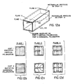
- septum polarizers 104, 106 serve to couple two rectangular waveguides 154, 156 (each propagating the TE10 mode) with a single square waveguide 152 having two propagating modes (which may be defined as the TE10 and TE01 modes or two linear combinations of these modes which are selected to be orthogonal to each other). Since the two modes propagating in the square waveguide 152 are orthogonal, the device is a four-port network with (for instance) port 1 being vertical polarization (TE10) in the square waveguide 152, port 3 being horizontal polarization (TE01) in the square waveguide 152, and ports 2 and 4 being the two rectangular waveguide ports 154, 156.
- TE10 vertical polarization
- TE01 horizontal polarization
- a horizontally polarized wave applied to the square waveguide 152 (excitation of port 3) will produce waves equal in magnitude but opposite in phase at the two rectangular waveguide ports 154, 156 (out-of-phase coupling to ports 2 and 4).
- the septum polarizer performs identically to a magic tee with vertical polarization at the input being equivalent to the sum port, horizontal polarization at the input equivalent to the difference port, and the two (rectangular waveguide) outputs being analogous to the colinear ports of the magic tee. If the device is symmetrical and impedance matched, then its scattering matrix will be that shown below.
- the insertion phase from vertical polarization in the square waveguide 152 to either the rectangular waveguide ports 154, 156 is, in general, different than that from horizontal polarization to the rectangular waveguide ports 154, 156 due to the operation of the polarizer itself (although the possibility of designing the polarizer so that these two phases would be identical is not necessarily excluded). It is, however, possible to add insertion phase trimming devices (such as thin vertical or horizontal polarized dielectric vanes) in the square waveguide 152 which will make ⁇ 1 equal to ⁇ 2 at least over a limited range of frequencies. If this is accomplished, then the scattering matrix becomes that shown below.
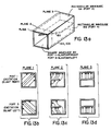
- the excitation of the square waveguide 152 may be defined as a combination of any two orthogonal modes propagating through this structure. If these modes are chosen to be slant 45 ⁇ right (TE10 + TE01) and slant 45 ⁇ left (TE10 - TE01) ports 1 and 3 will be re-defined. If phase matching (such as was necessary to arrive at equation [2] above) has been accomplished then the septum polarizer will operate as is shown in Figures 13A-D and have the scattering matrix shown below.
- Figure 13A is identical to Figure 12A and is identically labelled.
- Figures 13b-d demonstrate how the septum polarizers 104, 106 respond to slant right and slant left excitations to route the input signal to port 2 and 3, respectively, while shifting the signal polarization to vertical polarization.
- FIG. 15A and B The operation of the Faraday rotators 108, 110, which is illustrated in Figures 15A and B depends upon the Faraday rotation effect by which the polarization of electromagnetic wave propagating in a longitudinally magnetized ferrite rod 170 will rotate as the wave progresses.
- a circular or square waveguide 172 is generally used with a smaller ferrite rod whose axis coincides with the axis of the waveguide although fully ferrite filled versions are possible.
- FIG. 15a and 15b A typical realization is illustrated in Figure 15a and 15b.
- an incident wave whose electric field is vertically polarized will be rotated through an angle ⁇ °.
- Figure 15b a wave propagating in the opposite direction will also be rotated through ⁇ ° but in the same direction.
- a vertically polarized wave might rotate to an angle 45° removed from vertical when passing through the device but due to the nonreciprocal properties, an identically polarized wave (45° removed from vertical) reflected back to the output port would not be restored to the initial vertical polarization. Instead, it would continue to rotate in the same sense as before, emerging from the input as a horizontally polarized signal.
- the polarization selector 112, 114 shown at either end of the assembly illustrated in Figure 10 is simply a resistive vane 113 whose plane is oriented perpendicular to the E-field of the desired electromagnetic wave emerging from the phase shifting assembly. Since these vanes are thin and lie in a plane perpendicular to the E-field of the vertically polarized wave, the desired waves will be transmitted with little attenuation. Undesired signals whose electric fields are oriented parallel to the plane of the resistive vane 113 will be almost completely absorbed if the design of these vane (resistivity and physical dimensions) is properly chosen.
- this structure is comprised of two twin-slab non-reciprocal phase shifters 100, 102 which share common waveguide wall 103, two septum polarizers 104, 106, two Faraday rotators 108, 110, and two absorptive vane polarization selectors 112, 114 interconnected as is illustrated in Figure 16A.
- the combination of a septum polarizer and Faraday rotator 108 functions as a nonreciprocal four-port circulator yielding the equivalent circuit of Figure 11 wherein a wave entering at port 1 is routed through phase shifter 1 and then directly to the output at port 2. A signal entering at port 2 is routed through phase shifter 2 and then to the output at port 1.
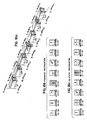
- the Faraday rotator 108 is magnetized so that the polarization of the E-field will be rotated by ferrite rod 170 through 45° and, consequently, a slant-45°-right polarized wave will be delivered at the input of the septum polarizer 104 (Section C+-C+).
- the septum polarizer 104 will deliver all of the energy contained in such a wave to the lower waveguide at its output (Section D+-D+) which leads directly to the lower phase shifter 102.
- the wave Emerging from the phase shifter 102 (Section E+-E+) the wave is converted to slant-45°-right polarization at the input to the Faraday rotator 110(Section F+-F+) rotated 45 ⁇ counterclockwise to yield a vertically polarized signal at the entrance to the polarization selector 114 (Section G+-G+) and then delivered essentially unattenuated with vertical polarization to the output of the phase shifter assembly (Section H+-H+). Any horizontal component of the wave which might be created due to imperfections in the Faraday rotators 108, 110 or septum polarizers 104, 106 will be absorbed by the resistive vane 113 within the polarization selector.
- Phase shifters 100 and 102 are switched to remanent states which are equal in magnitude but opposite in sense and, as a result, waves propagating in either direction are given identical phase shift.
- the insertion phase of the fast switching phase shifting assembly is modified by simultaneously switching the upper and lower phase shifters to new states which are again equal in magnitude but opposite in sense so that the phase shift provided by the assembly maintains reciprocal properties.
- this structure shows square waveguides being used in the polarization selectors 112,114, Faraday rotators 108, 110, and septum polarizers 104, 106, it is contemplated by the present invention that other dual-mode waveguide configurations (e.g., circular waveguide and cruciform quadridge waveguide, etc.) may alternatively be utilized.
- other dual-mode waveguide configurations e.g., circular waveguide and cruciform quadridge waveguide, etc.
- the forward and reverse propagating waves receive different phase shifts.
- an electronically scanned antenna e.g., phased array antenna
- a broad beam might be desired for transmit and a pencil beam for receive.
- the structure of Figure 16 allows such an operation to be achieved if the upper and lower phase shifters are controlled by separate electronic drivers and set to separate phase shift states.
- FIG. 17A a transmitter 192 may be connected to port 3, an antenna 196 connected to port 1, and a receiver 194 to port 2.
- the equivalent circuit of Figure 18 can also be realized by the structure of Figure 19.
- This device is also a modification of the basic fast switching pseudoreciprocal phase shifter of Figure 10.
- the output polarization selector 114 and Faraday rotator 110 have been removed but the output septum polarizer 106 remains.
- a wave applied to port 1 shown in Figure 19 will pass through the lower twin.slab phase shifter 102 and be delivered at the output of the septum polarizer 106 with a linear polarization rotated 45° to the right of vertical when viewed in the direction of propagation (from port 1).
- This particular structure may be utilized with a dual-polarized radiating element (at the end corresponding to port 2 and port 3) in a space-fed phased array.
- port 1 would transmit to and receive signals from free space while port 2 would deliver signals to and port 3 receive signals from the space feed.
- a dual-polarized antenna with separate polarization outputs (for example a dual-polarization horn attached to a orthomode transducer) would be used at the other end of the space feed to separate signals having orthogonal polarizations into the transmitter and receiver paths.
Landscapes
- Variable-Direction Aerials And Aerial Arrays (AREA)
- Waveguide Switches, Polarizers, And Phase Shifters (AREA)
Applications Claiming Priority (2)
| Application Number | Priority Date | Filing Date | Title |
|---|---|---|---|
| US145112 | 1988-01-19 | ||
| US07/145,112 US4884045A (en) | 1988-01-19 | 1988-01-19 | Fast switching reciprocal ferrite phase shifter |
Publications (2)
| Publication Number | Publication Date |
|---|---|
| EP0325340A2 true EP0325340A2 (fr) | 1989-07-26 |
| EP0325340A3 EP0325340A3 (fr) | 1990-08-22 |
Family
ID=22511653
Family Applications (1)
| Application Number | Title | Priority Date | Filing Date |
|---|---|---|---|
| EP89300001A Withdrawn EP0325340A3 (fr) | 1988-01-19 | 1989-01-03 | Déphaseur réciproque à ferrite à commutation rapide |
Country Status (2)
| Country | Link |
|---|---|
| US (1) | US4884045A (fr) |
| EP (1) | EP0325340A3 (fr) |
Cited By (6)
| Publication number | Priority date | Publication date | Assignee | Title |
|---|---|---|---|---|
| RU2165118C2 (ru) * | 1999-06-15 | 2001-04-10 | Научно-Исследовательский Институт Приборостроения | Фазированная антенная решетка |
| EP1137096A1 (fr) * | 2000-03-20 | 2001-09-26 | The Boeing Company | Diviseur/combinateur de puissance variable |
| RU2184410C1 (ru) * | 2001-06-26 | 2002-06-27 | Открытое акционерное общество "Научно-производственное объединение "Алмаз" им. акад. А.А. Расплетина" | Приемопередающий элемент фазированной антенной решетки |
| RU2470426C1 (ru) * | 2011-07-18 | 2012-12-20 | Общество с ограниченной ответственностью "Научно-производственное объединение "Завод Магнетон" | Элемент фазированной антенной решетки |
| RU2474018C2 (ru) * | 2010-12-30 | 2013-01-27 | Государственное образовательное учреждение высшего профессионального образования "Московский государственный технический университет имени Н.Э. Баумана (МГТУ им. Н.Э. Баумана) | Элемент фазированной отражательной антенной решетки |
| CN115498380A (zh) * | 2022-08-19 | 2022-12-20 | 西南应用磁学研究所(中国电子科技集团公司第九研究所) | 差相移铁氧体锁式开关单独激励方法 |
Families Citing this family (14)
| Publication number | Priority date | Publication date | Assignee | Title |
|---|---|---|---|---|
| US5129099A (en) * | 1989-03-30 | 1992-07-07 | Electromagnetic Sciences, Inc. | Reciprocal hybrid mode rf circuit for coupling rf transceiver to an rf radiator |
| US5144319A (en) * | 1991-03-14 | 1992-09-01 | Electromagnetic Sciences, Inc. | Planar substrate ferrite/diode phase shifter for phased array applications |
| US5304999A (en) * | 1991-11-20 | 1994-04-19 | Electromagnetic Sciences, Inc. | Polarization agility in an RF radiator module for use in a phased array |
| US6104342A (en) * | 1995-02-15 | 2000-08-15 | Raytheon Company | Scanned antenna array comprising a ferrite scanning line source |
| US5955998A (en) * | 1995-08-14 | 1999-09-21 | Ems Technologies, Inc. | Electronically scanned ferrite line source |
| US5660386A (en) * | 1996-05-28 | 1997-08-26 | Krieger; George | Ball throwing apparatus and method |
| US6867664B2 (en) * | 2003-05-05 | 2005-03-15 | Joey Bray | Ferrite-filled, antisymmetrically-biased rectangular waveguide phase shifter |
| US7501909B2 (en) * | 2005-06-09 | 2009-03-10 | California Institute Of Technology | Wide-bandwidth polarization modulator for microwave and mm-wavelengths |
| JP5446552B2 (ja) * | 2009-07-30 | 2014-03-19 | ソニー株式会社 | 無線通信装置、回転構造体、電子機器 |
| RU2439759C1 (ru) * | 2010-11-08 | 2012-01-10 | Общество с ограниченной ответственностью "Научно-производственное объединение "Завод Магнетон" | Элемент фазированной антенной решетки |
| US9843104B2 (en) * | 2015-02-27 | 2017-12-12 | Viasat, Inc. | Enhanced directivity feed and feed array |
| US11329391B2 (en) | 2015-02-27 | 2022-05-10 | Viasat, Inc. | Enhanced directivity feed and feed array |
| TR201800404A2 (tr) * | 2018-01-11 | 2019-07-22 | Aselsan Elektronik Sanayi Ve Ticaret As | Yüksek Ortalama RF Güce Dayanabilen Ferrit Faz Kaydırıcı |
| US11258149B2 (en) * | 2018-02-14 | 2022-02-22 | The Board Of Trustees Of The Leland Stanford Junior University | Non-reciprocal microwave window |
Family Cites Families (10)
| Publication number | Priority date | Publication date | Assignee | Title |
|---|---|---|---|---|
| US3289111A (en) * | 1964-03-04 | 1966-11-29 | Ferrotec Inc | Ferrite device utilizing the shorted turn effect, with electromagnet winding inside waveguide and adjacent to ferrite material |
| US3411113A (en) * | 1966-12-02 | 1968-11-12 | Sperry Rand Corp | Microwave gyromagnetic device wherein the gyromagnetic member has several parallel apertures throughout its length |
| US3500460A (en) * | 1967-05-17 | 1970-03-10 | Westinghouse Electric Corp | Microwave polarization switch |
| US3555463A (en) * | 1967-10-21 | 1971-01-12 | Tdk Electronics Co Ltd | Reciprocal microwave phase shifter having a plurality of longitudinal and transverse energizing conductors passing through the ferrimagnetic material |
| FR2038614A5 (fr) * | 1969-03-20 | 1971-01-08 | Thomson Csf | |
| US3626335A (en) * | 1969-11-10 | 1971-12-07 | Emerson Electric Co | Phase-shifting means |
| US3982213A (en) * | 1975-04-16 | 1976-09-21 | United Technologies Corporation | Monolithic reciprocal latching ferrite phase shifter |
| IT1226273B (it) * | 1979-08-07 | 1990-12-27 | Sits Soc It Telecom Siemens | Dispositivo per l'accordo elettronico di un magnetron di potenza. |
| US4445098A (en) * | 1982-02-19 | 1984-04-24 | Electromagnetic Sciences, Inc. | Method and apparatus for fast-switching dual-toroid microwave phase shifter |
| US4467292A (en) * | 1982-09-30 | 1984-08-21 | Hughes Aircraft Company | Millimeter-wave phase shifting device |
-
1988
- 1988-01-19 US US07/145,112 patent/US4884045A/en not_active Expired - Fee Related
-
1989
- 1989-01-03 EP EP89300001A patent/EP0325340A3/fr not_active Withdrawn
Cited By (8)
| Publication number | Priority date | Publication date | Assignee | Title |
|---|---|---|---|---|
| RU2165118C2 (ru) * | 1999-06-15 | 2001-04-10 | Научно-Исследовательский Институт Приборостроения | Фазированная антенная решетка |
| EP1137096A1 (fr) * | 2000-03-20 | 2001-09-26 | The Boeing Company | Diviseur/combinateur de puissance variable |
| US6377133B1 (en) | 2000-03-20 | 2002-04-23 | Hughes Electronics Corporation | Variable power divider/combiner |
| RU2184410C1 (ru) * | 2001-06-26 | 2002-06-27 | Открытое акционерное общество "Научно-производственное объединение "Алмаз" им. акад. А.А. Расплетина" | Приемопередающий элемент фазированной антенной решетки |
| RU2474018C2 (ru) * | 2010-12-30 | 2013-01-27 | Государственное образовательное учреждение высшего профессионального образования "Московский государственный технический университет имени Н.Э. Баумана (МГТУ им. Н.Э. Баумана) | Элемент фазированной отражательной антенной решетки |
| RU2470426C1 (ru) * | 2011-07-18 | 2012-12-20 | Общество с ограниченной ответственностью "Научно-производственное объединение "Завод Магнетон" | Элемент фазированной антенной решетки |
| CN115498380A (zh) * | 2022-08-19 | 2022-12-20 | 西南应用磁学研究所(中国电子科技集团公司第九研究所) | 差相移铁氧体锁式开关单独激励方法 |
| CN115498380B (zh) * | 2022-08-19 | 2024-01-16 | 西南应用磁学研究所(中国电子科技集团公司第九研究所) | 差相移铁氧体锁式开关单独激励方法 |
Also Published As
| Publication number | Publication date |
|---|---|
| US4884045A (en) | 1989-11-28 |
| EP0325340A3 (fr) | 1990-08-22 |
Similar Documents
| Publication | Publication Date | Title |
|---|---|---|
| US4884045A (en) | Fast switching reciprocal ferrite phase shifter | |
| US5304999A (en) | Polarization agility in an RF radiator module for use in a phased array | |
| Parker et al. | Phased arrays-part II: implementations, applications, and future trends | |
| Yoneda et al. | A design of novel grooved circular waveguide polarizers | |
| US5129099A (en) | Reciprocal hybrid mode rf circuit for coupling rf transceiver to an rf radiator | |
| US4613869A (en) | Electronically scanned array antenna | |
| CA1181822A (fr) | Element a commande de phase avec commande de polarisation | |
| US4564824A (en) | Adjustable-phase-power divider apparatus | |
| US4034377A (en) | Ferrite circulators and isolators and circuits incorporating the same | |
| US3938158A (en) | Antenna element for circular or linear polarization | |
| US3626335A (en) | Phase-shifting means | |
| US3698008A (en) | Latchable, polarization-agile reciprocal phase shifter | |
| US3982213A (en) | Monolithic reciprocal latching ferrite phase shifter | |
| Ince et al. | Phasers and time delay elements | |
| US4881052A (en) | Millimeter wave microstrip nonreciprocal phase shifter | |
| US4443800A (en) | Polarization control element for phased array antennas | |
| US3445851A (en) | Polarization insensitive microwave energy phase shifter | |
| US3500460A (en) | Microwave polarization switch | |
| US2867772A (en) | Microwave circulator | |
| US4201961A (en) | Unidirectional phase shifter | |
| EP3312933A1 (fr) | Régulateur de phase d'ondes ultra-courtes | |
| US3845421A (en) | Polarization insensitive transmission phase shifter | |
| Sorensen et al. | Low-cost nonplanar microstrip-line ferrite phase shifter utilizing circular polarization | |
| US3355682A (en) | Latching-type digital phase shifter employing toroids of gyromagnetic material | |
| JPS60187103A (ja) | 導波管形可変電力分配器 |
Legal Events
| Date | Code | Title | Description |
|---|---|---|---|
| PUAI | Public reference made under article 153(3) epc to a published international application that has entered the european phase |
Free format text: ORIGINAL CODE: 0009012 |
|
| AK | Designated contracting states |
Kind code of ref document: A2 Designated state(s): AT BE CH DE ES FR GB GR IT LI LU NL SE |
|
| DIN1 | Information on inventor provided before grant (deleted) | ||
| RAP1 | Party data changed (applicant data changed or rights of an application transferred) |
Owner name: ELECTROMAGNETIC SCIENCES, INC. |
|
| RIN1 | Information on inventor provided before grant (corrected) |
Inventor name: FULLER, JAMES A. Inventor name: ALVERSON, WILLIAM K |
|
| PUAL | Search report despatched |
Free format text: ORIGINAL CODE: 0009013 |
|
| AK | Designated contracting states |
Kind code of ref document: A3 Designated state(s): AT BE CH DE ES FR GB GR IT LI LU NL SE |
|
| 17P | Request for examination filed |
Effective date: 19901228 |
|
| STAA | Information on the status of an ep patent application or granted ep patent |
Free format text: STATUS: THE APPLICATION HAS BEEN WITHDRAWN |
|
| 18W | Application withdrawn |
Withdrawal date: 19921123 |