EP0325357B1 - Eclairage d'espace - Google Patents
Eclairage d'espace Download PDFInfo
- Publication number
- EP0325357B1 EP0325357B1 EP89300219A EP89300219A EP0325357B1 EP 0325357 B1 EP0325357 B1 EP 0325357B1 EP 89300219 A EP89300219 A EP 89300219A EP 89300219 A EP89300219 A EP 89300219A EP 0325357 B1 EP0325357 B1 EP 0325357B1
- Authority
- EP
- European Patent Office
- Prior art keywords
- space
- tubular member
- generally tubular
- lamp
- fitting according
- Prior art date
- Legal status (The legal status is an assumption and is not a legal conclusion. Google has not performed a legal analysis and makes no representation as to the accuracy of the status listed.)
- Expired - Lifetime
Links
- 239000000463 material Substances 0.000 claims description 8
- 238000005286 illumination Methods 0.000 description 4
- 238000003780 insertion Methods 0.000 description 1
- 230000037431 insertion Effects 0.000 description 1
- 238000009434 installation Methods 0.000 description 1
- 229920003023 plastic Polymers 0.000 description 1
- 239000004033 plastic Substances 0.000 description 1
- 230000011664 signaling Effects 0.000 description 1
Images

Classifications
-
- F—MECHANICAL ENGINEERING; LIGHTING; HEATING; WEAPONS; BLASTING
- F21—LIGHTING
- F21S—NON-PORTABLE LIGHTING DEVICES; SYSTEMS THEREOF; VEHICLE LIGHTING DEVICES SPECIALLY ADAPTED FOR VEHICLE EXTERIORS
- F21S8/00—Lighting devices intended for fixed installation
- F21S8/04—Lighting devices intended for fixed installation intended only for mounting on a ceiling or the like overhead structures
-
- F—MECHANICAL ENGINEERING; LIGHTING; HEATING; WEAPONS; BLASTING
- F21—LIGHTING
- F21S—NON-PORTABLE LIGHTING DEVICES; SYSTEMS THEREOF; VEHICLE LIGHTING DEVICES SPECIALLY ADAPTED FOR VEHICLE EXTERIORS
- F21S8/00—Lighting devices intended for fixed installation
- F21S8/04—Lighting devices intended for fixed installation intended only for mounting on a ceiling or the like overhead structures
- F21S8/06—Lighting devices intended for fixed installation intended only for mounting on a ceiling or the like overhead structures by suspension
-
- F—MECHANICAL ENGINEERING; LIGHTING; HEATING; WEAPONS; BLASTING
- F21—LIGHTING
- F21S—NON-PORTABLE LIGHTING DEVICES; SYSTEMS THEREOF; VEHICLE LIGHTING DEVICES SPECIALLY ADAPTED FOR VEHICLE EXTERIORS
- F21S8/00—Lighting devices intended for fixed installation
- F21S8/08—Lighting devices intended for fixed installation with a standard
- F21S8/081—Lighting devices intended for fixed installation with a standard of low-built type, e.g. landscape light
-
- F—MECHANICAL ENGINEERING; LIGHTING; HEATING; WEAPONS; BLASTING
- F21—LIGHTING
- F21V—FUNCTIONAL FEATURES OR DETAILS OF LIGHTING DEVICES OR SYSTEMS THEREOF; STRUCTURAL COMBINATIONS OF LIGHTING DEVICES WITH OTHER ARTICLES, NOT OTHERWISE PROVIDED FOR
- F21V17/00—Fastening of component parts of lighting devices, e.g. shades, globes, refractors, reflectors, filters, screens, grids or protective cages
- F21V17/02—Fastening of component parts of lighting devices, e.g. shades, globes, refractors, reflectors, filters, screens, grids or protective cages with provision for adjustment
-
- F—MECHANICAL ENGINEERING; LIGHTING; HEATING; WEAPONS; BLASTING
- F21—LIGHTING
- F21V—FUNCTIONAL FEATURES OR DETAILS OF LIGHTING DEVICES OR SYSTEMS THEREOF; STRUCTURAL COMBINATIONS OF LIGHTING DEVICES WITH OTHER ARTICLES, NOT OTHERWISE PROVIDED FOR
- F21V17/00—Fastening of component parts of lighting devices, e.g. shades, globes, refractors, reflectors, filters, screens, grids or protective cages
- F21V17/04—Fastening of component parts of lighting devices, e.g. shades, globes, refractors, reflectors, filters, screens, grids or protective cages the fastening being onto or by the light source
-
- F—MECHANICAL ENGINEERING; LIGHTING; HEATING; WEAPONS; BLASTING
- F21—LIGHTING
- F21V—FUNCTIONAL FEATURES OR DETAILS OF LIGHTING DEVICES OR SYSTEMS THEREOF; STRUCTURAL COMBINATIONS OF LIGHTING DEVICES WITH OTHER ARTICLES, NOT OTHERWISE PROVIDED FOR
- F21V7/00—Reflectors for light sources
- F21V7/0008—Reflectors for light sources providing for indirect lighting
- F21V7/0016—Reflectors for light sources providing for indirect lighting on lighting devices that also provide for direct lighting, e.g. by means of independent light sources, by splitting of the light beam, by switching between both lighting modes
-
- F—MECHANICAL ENGINEERING; LIGHTING; HEATING; WEAPONS; BLASTING
- F21—LIGHTING
- F21Y—INDEXING SCHEME ASSOCIATED WITH SUBCLASSES F21K, F21L, F21S and F21V, RELATING TO THE FORM OR THE KIND OF THE LIGHT SOURCES OR OF THE COLOUR OF THE LIGHT EMITTED
- F21Y2103/00—Elongate light sources, e.g. fluorescent tubes
Definitions
- This invention relates to a space lighting, that is to say lighting for illuminating spaces such as rooms of dwelling houses or offices or theatres or even for outdoor spaces such as patios.
- tubular lamps such as fluorescent tubes
- fittings comprise a reflector behind the tube with an optional diffuser prismatic controller, or lensed refractor in front of the tube
- tubular lamps are used to give indirect lighting by being concealed within pelmets or under soffits or within alcoves where, however, they may provide direct illumination on to objects displayed within the alcove, but some indirect illumination into the room space beyond the alcove by reflection from the walls and ceiling of the alcove.
- shaded lamps can be adjusted, for example, desk and table lamps, to direct light at a working area, mostly lamps are designed to be permanently positioned to provide direct illumination or indirect illumination in order to achieve a permanent, desired lighting effect in a room, office or other space.
- tubular lamps such as fluorescent tubes
- the fittings for tubular lamps, such as fluorescent tubes have been on the whole typical of such permanently deployed lighting fittings.
- DE-U-8523101 discloses a space lighting fitting comprising a support, lamp holder means and light directing means (5,5') adjustable between first (see Figure 1) and second (see Figure 2) positions giving direct and indirect lighting respectively.
- DE-C-885382 discloses a light fitting in which reflectors 4 are pivoted for altering the lighting direction; two reflectors are moved together by a ratchet mechanism.
- GB-A-2082744 discloses adjustable lighting apparatus comprising a shaped back plate (1) and a substantially parallel shaped front plate (7) which plates are spaced apart by triangular end panels so as to form smaller and larger apertures (15,16), these apertures having corresponding openable shutters (17,18).
- At least one fluorescent or other rectilinear, tubular source of light (25) extends fixedly and perpendicularly between the two end panels and has a reflector (28) turnable about its own longitudinal axis or an axis spaced a short distance therefrom.
- BE-A-540548 discloses ( Figure 2) a table lamp fitting comprising a light directing means (4,5,13,14,15 and 16) which surrounds a lamp (6) held in a lamp holder means (8).
- the present invention provides improved lighting fittings that give more flexibility of lighting effect whereby a single lamp can be permanently or adjustably deployed in a variety of configurations.
- the invention comprises a space lighting fitting for illuminating a space and comprising support means for attaching the fitting to a wall or ceiling surface which borders the space, lamp holder means connected to the fitting for holding an elongated lamp therein, the lamp having a longitudinal axis, light directing means adjustable between first and second positions giving direct and indirect light respectively to the space, characterised in that it comprises a generally tubular member extending along said longitudinal axis and rotatable thereabout, said generally tubular member comprising a major arcuate portion of translucent material having a first inside curvature centred on said axis and a minor arcuate portion comprising a reflector and having a reflecting surface having a second inside curvature less than said first inside curvature and, in said first position, transmitting light from the lamp directly into said space through said translucent material and in said second position reflecting light from said lamp off said wall or ceiling surface.
- the said reflecting surface may be silvered, or may be enamelled.
- the said translucent material may comprise prismatic controller means, or may comprise lensed refractor means.
- the fitting may comprise a motor connected to drive the generally tubular member in rotation.
- the said generally tubular member and the motor may have meshing gears.
- the motor may have a lay shaft extending along the generally tubular member and drivingly connected to a generally tubular member at each end thereof.
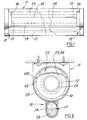
- Figures 1-3 illustrate a space lighting fitting 11 comprising lamp holder means 12 for a fluorescent tube 13 and light directing means 14 supported for rotation about the lamp holder means 12, and adjustment means 15 adapted to rotate said light directing means 14 about said lamp holder means 12, the light directing means 14 and the lamp holder means 12 being coaxial.
- the adjustment means 15 comprise rings 16 surrounding the lamp holder means 12 at each end of the tube 13 and fixed with respect to the light directing means 12, and locating means 17 to hold the rings 16 and hence the light directing means 14 in a set position.
- the locating means 17 comprise a motor 18 connected to drive the ring - which may be a stepping motor controlled e.g. by a wall switch or an infra-red signalling device or actuated by some automatic control arrangement such as a photocell which adjusts to suit ambient light conditions, or by a control signal for operating a plurality of lamps together, as in an office or factory, operating, for example, on a 0.5 to 10 volt d.c. superimposed on or sent separately from the a.c. mains supply.
- the motor 18 is connected to drive the ring by meshing with it via an idler 19.
- the motor 18 acts on the rings 16 at both ends of the tube 13 via a lay shaft 21 extending parallel to the tube 13.
- the light directing means 14 surround the tube 13 and comprise reflector means 22 which comprise an arcuate member 23 (which might have for example a silvered or an enamelled surface 24) having a lesser curvature than the cylinder (illustrated in broken line) which is the locus of its rotation about the axis of the tube 13 (hence of the lamp holder means 12).
- the light directing means 14 also comprise diffuser, prismatic controller or lensed refractor means 25, which are circular cylindrical and coaxial with their axis of rotation about the tube 13.
- the light directing means 14 comprise a circular cylindrical shell 14a surrounding the tube 13 and having the reflector means 22 internally thereof.
- the space lighting fitting can be installed as by screwing it to a ceiling as shown in Figure 2.
- the tube 13 is removable together with with light directing means for such installation and also of course for the replacement of fluorescent tubes.
- “meshing” of course is also to be understood a frictional drive without gear-type teeth, which might facilitate the insertion and removal of the light directing means together with the fluorescent tube.
- the diffuser, prismatic controller or lensed refractor means 25 can be made of a resilient plastics material so that it can be sprung into and out from engagement with the reflector means 22 to facilitate independent access.
- the arrangements provides a simple and neat solution to the problem of adjustable lighting especially in situations where the lighting fittings are not readily accessible e.g. on a ceiling or high up on a wall. But, with or without the motor or other automatic or remote control arrangement, the fittings can be adapted for use in connection with standard lamps, desk lamps and lamps which are built in to domestic commercial or industrial furniture.
Landscapes
- Engineering & Computer Science (AREA)
- General Engineering & Computer Science (AREA)
- Non-Portable Lighting Devices Or Systems Thereof (AREA)
- Securing Globes, Refractors, Reflectors Or The Like (AREA)
Claims (8)
- Applique d'éclairage d'espace (11) pour éclairer un espace et comprenant un moyen formant support pour fixer l'applique à une surface de mur ou de plafond qui borde l'espace, un moyen support de lampe (12) relié à l'applique (11) pour supporter à l'intérieur une lampe allongée (13), la lampe (13) ayant un axe longitudinal, un moyen d'orientation de la lumière (14) réglable entre des première et seconde positions donnant, respectivement, de la lumière directe et de la lumière indirecte à l'espace, caractérisée en ce qu'elle comprend un élément globalement tubulaire s'étendant le long dudit axe longitudinal et mobile en rotation autour de celui-ci, ledit élément globalement tubulaire (14) comprenant une partie principale en forme d'arc (25) en une matière translucide ayant une première courbure intérieure (23) centrée sur ledit axe, et une partie secondaire en forme d'arc comprenant un réflecteur et ayant une surface réfléchissante (24) ayant une seconde courbure intérieure plus petite que ladite première courbure intérieure et, dans ladite première position, transmettant la lumière issue de la lampe (13) directement dans ledit espace à travers ladite matière translucide (25), et, dans ladite seconde position, réfléchissant la lumière issue de ladite lampe (13) à partir de ladite surface de mur ou de plafond.
- Applique d'éclairage d'espace selon la revendication 1, caractérisée en ce que ladite surface réfléchissante (24) est argentée.
- Applique d'éclairage d'espace selon la revendication 1, caractérisée en ce que ladite surface réfléchissante (24) est émaillée.
- Applique d'éclairage d'espace selon l'une quelconque des revendications 1 à 3, caractérisée en ce que ladite matière translucide (25) comprend un moyen de commande à base de prismes.
- Applique d'éclairage d'espace selon l'une quelconque des revendications 1 à 3, caractérisée en ce que ladite matière translucide (25) comprend un moyen de réfraction à base de lentilles.
- Applique d'éclairage d'espace selon l'une quelconque des revendications 1 à 5, caractérisée en ce qu'elle comprend un moteur (18) monté de manière à entraîner en rotation l'élément globalement tubulaire (14).
- Applique d'éclairage d'espace selon la revendication 6, caractérisée en ce que ledit élément globalement tubulaire (14) et ledit moteur (18) ont des engrenages en prise.
- Applique d'éclairage d'espace selon la revendication 6, caractérisée en ce que ledit moteur (18) comporte un arbre intermédiaire (21) s'étendant le long de l'élément globalement tubulaire (14) et relié à l'élément globalement tubulaire (14), au droit de chacune de ses extrémités, de manière à l'entraîner.
Priority Applications (1)
| Application Number | Priority Date | Filing Date | Title |
|---|---|---|---|
| AT89300219T ATE102698T1 (de) | 1988-01-20 | 1989-01-11 | Raumbeleuchtung. |
Applications Claiming Priority (4)
| Application Number | Priority Date | Filing Date | Title |
|---|---|---|---|
| GB8801221 | 1988-01-20 | ||
| GB888801221A GB8801221D0 (en) | 1988-01-20 | 1988-01-20 | Space lighting |
| GB888804847A GB8804847D0 (en) | 1988-03-01 | 1988-03-01 | Space lighting |
| GB8804847 | 1988-03-01 |
Publications (3)
| Publication Number | Publication Date |
|---|---|
| EP0325357A2 EP0325357A2 (fr) | 1989-07-26 |
| EP0325357A3 EP0325357A3 (en) | 1990-04-18 |
| EP0325357B1 true EP0325357B1 (fr) | 1994-03-09 |
Family
ID=26293343
Family Applications (1)
| Application Number | Title | Priority Date | Filing Date |
|---|---|---|---|
| EP89300219A Expired - Lifetime EP0325357B1 (fr) | 1988-01-20 | 1989-01-11 | Eclairage d'espace |
Country Status (5)
| Country | Link |
|---|---|
| US (2) | US5003445A (fr) |
| EP (1) | EP0325357B1 (fr) |
| JP (1) | JPH01309203A (fr) |
| DE (1) | DE68913560D1 (fr) |
| GB (1) | GB2214285B (fr) |
Families Citing this family (11)
| Publication number | Priority date | Publication date | Assignee | Title |
|---|---|---|---|---|
| FR2653530B1 (fr) * | 1989-10-19 | 1992-01-17 | Emc2 | Dispositif d'eclairage electrique direct ou indirect, notamment lampe murale ou lampadaire. |
| DE4024738C2 (de) * | 1990-08-03 | 1995-04-27 | Siemens Ag | Indirekte Spiegelleuchte |
| JP3961652B2 (ja) * | 1997-12-03 | 2007-08-22 | 株式会社小糸製作所 | 車輌用前照灯 |
| US6652118B2 (en) | 2000-05-08 | 2003-11-25 | Sylvan R. Shemitz Designs, Inc. | Asymmetric distribution luminaire |
| USD463879S1 (en) | 2002-01-22 | 2002-10-01 | Genlyte Thomas Group Llc | Luminaire housing |
| US7128443B2 (en) * | 2002-06-28 | 2006-10-31 | Koninklijke Philips Electronics, N.V. | Light-collimating system |
| US20050005529A1 (en) * | 2003-07-10 | 2005-01-13 | David Brault | Lighting system for a greenhouse |
| US20050201103A1 (en) * | 2004-03-12 | 2005-09-15 | Honeywell International Inc. | Luminaires with batwing light distribution |
| US7556402B2 (en) * | 2004-03-29 | 2009-07-07 | Cooper Technologies Company | Direct-indirect luminaire with shutter |
| US20080055918A1 (en) * | 2006-08-31 | 2008-03-06 | Anthony Peter Mascadri | Vehicular lamp assembly having multiple moveable reflectors |
| CN103185306B (zh) * | 2011-12-28 | 2016-04-13 | 海洋王照明科技股份有限公司 | 筒灯面盖安装结构及筒灯 |
Family Cites Families (25)
| Publication number | Priority date | Publication date | Assignee | Title |
|---|---|---|---|---|
| BE540548A (fr) * | ||||
| DE236155C (fr) * | ||||
| US1902991A (en) * | 1930-10-01 | 1933-03-28 | Cardon Henry | Shell lamp |
| US2138373A (en) * | 1935-06-26 | 1938-11-29 | Earl L Canfield | Luminair |
| US2139707A (en) * | 1936-02-27 | 1938-12-13 | John W Van Denburg | Headlight system |
| US2118749A (en) * | 1937-02-02 | 1938-05-24 | Weaver May | Lamp |
| US2301419A (en) * | 1939-12-19 | 1942-11-10 | Lew Reuben | Lamp shade and the like |
| DE885382C (de) * | 1951-12-11 | 1953-08-03 | Siemens Ag | Strassenleuchte fuer Leuchtstofflampen mit verstellbaren Reflektoren, insbesondere Spiegelreflektoren |
| GB1193284A (en) * | 1966-08-05 | 1970-05-28 | Studio Artemide S A S Di E Gis | A Lamp Structure for Use as Table and Wall Lamp |
| NL7113220A (fr) * | 1970-10-02 | 1972-04-05 | ||
| US3769503A (en) * | 1972-06-23 | 1973-10-30 | Gen Electric | Lamp fixture having dichoric filter arrangement for selectively directing heat and light |
| DE2416404A1 (de) * | 1974-04-04 | 1975-10-16 | Helmut Dipl Ing Julinot | Lampe fuer leuchtstoffroehren bzw. rohroder stabfoermige beleuchtungskoerper |
| GB2037416B (en) * | 1978-12-21 | 1983-05-11 | Sassmannshause K | Lamps |
| US4232359A (en) * | 1979-04-09 | 1980-11-04 | Berkey-Colortran, Inc. | Spotlight or other illuminator |
| US4246629A (en) * | 1979-10-15 | 1981-01-20 | Louis Marrero | Fluorescent light fixture |
| GB2082744B (en) * | 1980-07-08 | 1983-12-14 | Planned Space Products Ltd | Adjustable lighting apparatus |
| SU956907A1 (ru) * | 1980-07-11 | 1982-09-07 | Предприятие П/Я А-3695 | Осветительное устройство с измен емой шириной светового пучка |
| US4323955A (en) * | 1980-07-21 | 1982-04-06 | Mark Edward H | Light with 360° rotatable cover |
| DE3212284A1 (de) * | 1982-04-02 | 1983-10-13 | Heinrich 6238 Hofheim Wendel | Leuchtengehaeuse |
| DE3316000A1 (de) * | 1983-05-03 | 1984-11-08 | Licentia Patent-Verwaltungs-Gmbh, 6000 Frankfurt | Leuchte fuer eine langgestreckte lichtquelle |
| DE8402555U1 (de) * | 1984-01-30 | 1985-05-30 | Patent-Treuhand-Gesellschaft für elektrische Glühlampen mbH, 8000 München | Leuchte für eine einseitig gesockelte elektrische Lampe |
| NL8500299A (nl) * | 1985-02-04 | 1986-09-01 | Poot Lichtenergie | Reflector. |
| DE8507634U1 (de) * | 1985-03-15 | 1985-11-14 | Licentia Patent-Verwaltungs-Gmbh, 6000 Frankfurt | Langgestreckte Leuchte mit eingebauter Spiegeloptik |
| EP0206702A3 (fr) * | 1985-06-21 | 1988-09-07 | RAYOVAC Corporation | Lampe portative avec ensemble de réflecteurs réglables |
| DE8523101U1 (de) * | 1985-08-10 | 1986-11-20 | Trilux-Lenze Gmbh + Co Kg, 5760 Arnsberg | Leuchte |
-
1989
- 1989-01-11 GB GB8900568A patent/GB2214285B/en not_active Expired - Lifetime
- 1989-01-11 DE DE89300219T patent/DE68913560D1/de not_active Expired - Lifetime
- 1989-01-11 EP EP89300219A patent/EP0325357B1/fr not_active Expired - Lifetime
- 1989-01-17 US US07/297,837 patent/US5003445A/en not_active Expired - Fee Related
- 1989-01-20 JP JP1013012A patent/JPH01309203A/ja active Pending
-
1990
- 1990-05-14 US US07/523,327 patent/US5014172A/en not_active Expired - Fee Related
Also Published As
| Publication number | Publication date |
|---|---|
| GB2214285B (en) | 1992-04-08 |
| EP0325357A3 (en) | 1990-04-18 |
| US5003445A (en) | 1991-03-26 |
| GB8900568D0 (en) | 1989-03-08 |
| EP0325357A2 (fr) | 1989-07-26 |
| JPH01309203A (ja) | 1989-12-13 |
| DE68913560D1 (de) | 1994-04-14 |
| US5014172A (en) | 1991-05-07 |
| GB2214285A (en) | 1989-08-31 |
Similar Documents
| Publication | Publication Date | Title |
|---|---|---|
| US8231242B2 (en) | Method and apparatus for lighting involving reflectors | |
| US4229782A (en) | High efficiency lighting units with beam cut-off angle | |
| US4344111A (en) | High efficiency lighting units and systems using same | |
| US6206548B1 (en) | Luminaire module having multiple rotatably adjustable reflectors | |
| EP1159857B1 (fr) | Accessoires reglables pour eclairage fluorescent | |
| US4939627A (en) | Indirect luminaire having a secondary source induced low brightness lens element | |
| US4054793A (en) | Lighting system | |
| US6152583A (en) | Adjustable luminaire having pivotable lamp and reflector assembly | |
| US6076943A (en) | Luminaire | |
| US6607289B2 (en) | Quick connect reflector holder | |
| US3805053A (en) | Fluorescent fixture | |
| US5014172A (en) | Space lighting | |
| EP0410582A1 (fr) | Armature pour éclairage spatial | |
| GB2305496A (en) | A lamp | |
| GB2149079A (en) | A lighting fitting | |
| US6007220A (en) | Reflectors for fluorescent light fixtures | |
| CN220119291U (zh) | 天花机灯具组件及天花机 | |
| EP1079176A1 (fr) | Luminaire | |
| TR2025012368Y (tr) | Işik dağilimi ve opti̇k özelli̇kleri̇ di̇gi̇tal olarak uzaktan deği̇şti̇ri̇lebi̇li̇r aydinlatma armatürü | |
| WO2004020897A1 (fr) | Luminaire | |
| EP0472288A2 (fr) | Améliorations concernant les luminaires | |
| WO1990004739A1 (fr) | Luminaire a eclairage indirect avec element diffuseur a lentille ayant une faible luminosite induite par une source secondaire | |
| IES85667Y1 (en) | A luminaire apparatus | |
| IES20090055A2 (en) | A luminaire apparatus | |
| JPH04274102A (ja) | 照明装置 |
Legal Events
| Date | Code | Title | Description |
|---|---|---|---|
| PUAI | Public reference made under article 153(3) epc to a published international application that has entered the european phase |
Free format text: ORIGINAL CODE: 0009012 |
|
| AK | Designated contracting states |
Kind code of ref document: A2 Designated state(s): AT BE CH DE ES FR GB GR IT LI LU NL SE |
|
| PUAL | Search report despatched |
Free format text: ORIGINAL CODE: 0009013 |
|
| AK | Designated contracting states |
Kind code of ref document: A3 Designated state(s): AT BE CH DE ES FR GB GR IT LI LU NL SE |
|
| RHK1 | Main classification (correction) |
Ipc: F21V 17/02 |
|
| 17P | Request for examination filed |
Effective date: 19900607 |
|
| 17Q | First examination report despatched |
Effective date: 19920519 |
|
| GRAA | (expected) grant |
Free format text: ORIGINAL CODE: 0009210 |
|
| AK | Designated contracting states |
Kind code of ref document: B1 Designated state(s): AT BE CH DE ES FR GB GR IT LI LU NL SE |
|
| PG25 | Lapsed in a contracting state [announced via postgrant information from national office to epo] |
Ref country code: IT Free format text: LAPSE BECAUSE OF FAILURE TO SUBMIT A TRANSLATION OF THE DESCRIPTION OR TO PAY THE FEE WITHIN THE PRE;WARNING: LAPSES OF ITALIAN PATENTS WITH EFFECTIVE DATE BEFORE 2007 MAY HAVE OCCURRED AT ANY TIME BEFORE 2007. THE CORRECT EFFECTIVE DATE MAY BE DIFFERENT FROM THE ONE RECORDED.SCRIBED TIME-LIMIT Effective date: 19940309 Ref country code: LI Effective date: 19940309 Ref country code: DE Effective date: 19940309 Ref country code: NL Effective date: 19940309 Ref country code: AT Effective date: 19940309 Ref country code: FR Free format text: THE PATENT HAS BEEN ANNULLED BY A DECISION OF A NATIONAL AUTHORITY Effective date: 19940309 Ref country code: SE Free format text: THE PATENT HAS BEEN ANNULLED BY A DECISION OF A NATIONAL AUTHORITY Effective date: 19940309 Ref country code: ES Free format text: THE PATENT HAS BEEN ANNULLED BY A DECISION OF A NATIONAL AUTHORITY Effective date: 19940309 Ref country code: CH Effective date: 19940309 Ref country code: BE Effective date: 19940309 Ref country code: GR Free format text: LAPSE BECAUSE OF FAILURE TO SUBMIT A TRANSLATION OF THE DESCRIPTION OR TO PAY THE FEE WITHIN THE PRESCRIBED TIME-LIMIT Effective date: 19940309 |
|
| REF | Corresponds to: |
Ref document number: 102698 Country of ref document: AT Date of ref document: 19940315 Kind code of ref document: T |
|
| REF | Corresponds to: |
Ref document number: 68913560 Country of ref document: DE Date of ref document: 19940414 |
|
| REG | Reference to a national code |
Ref country code: CH Ref legal event code: PL |
|
| EN | Fr: translation not filed | ||
| NLV1 | Nl: lapsed or annulled due to failure to fulfill the requirements of art. 29p and 29m of the patents act | ||
| PG25 | Lapsed in a contracting state [announced via postgrant information from national office to epo] |
Ref country code: GB Effective date: 19950111 |
|
| PLBE | No opposition filed within time limit |
Free format text: ORIGINAL CODE: 0009261 |
|
| STAA | Information on the status of an ep patent application or granted ep patent |
Free format text: STATUS: NO OPPOSITION FILED WITHIN TIME LIMIT |
|
| PG25 | Lapsed in a contracting state [announced via postgrant information from national office to epo] |
Ref country code: LU Free format text: LAPSE BECAUSE OF NON-PAYMENT OF DUE FEES Effective date: 19950131 |
|
| 26N | No opposition filed | ||
| GBPC | Gb: european patent ceased through non-payment of renewal fee |
Effective date: 19950111 |