EP0325377A2 - Regelvorrichtung für ein elektrisches Fahrzeug - Google Patents
Regelvorrichtung für ein elektrisches Fahrzeug Download PDFInfo
- Publication number
- EP0325377A2 EP0325377A2 EP89300315A EP89300315A EP0325377A2 EP 0325377 A2 EP0325377 A2 EP 0325377A2 EP 89300315 A EP89300315 A EP 89300315A EP 89300315 A EP89300315 A EP 89300315A EP 0325377 A2 EP0325377 A2 EP 0325377A2
- Authority
- EP
- European Patent Office
- Prior art keywords
- filter
- filter circuit
- control means
- electric vehicle
- filter capacitor
- Prior art date
- Legal status (The legal status is an assumption and is not a legal conclusion. Google has not performed a legal analysis and makes no representation as to the accuracy of the status listed.)
- Withdrawn
Links
Images

Classifications
-
- B—PERFORMING OPERATIONS; TRANSPORTING
- B60—VEHICLES IN GENERAL
- B60L—PROPULSION OF ELECTRICALLY-PROPELLED VEHICLES; SUPPLYING ELECTRIC POWER FOR AUXILIARY EQUIPMENT OF ELECTRICALLY-PROPELLED VEHICLES; ELECTRODYNAMIC BRAKE SYSTEMS FOR VEHICLES IN GENERAL; MAGNETIC SUSPENSION OR LEVITATION FOR VEHICLES; MONITORING OPERATING VARIABLES OF ELECTRICALLY-PROPELLED VEHICLES; ELECTRIC SAFETY DEVICES FOR ELECTRICALLY-PROPELLED VEHICLES
- B60L9/00—Electric propulsion with power supply external to the vehicle
- B60L9/005—Interference suppression
-
- B—PERFORMING OPERATIONS; TRANSPORTING
- B60—VEHICLES IN GENERAL
- B60L—PROPULSION OF ELECTRICALLY-PROPELLED VEHICLES; SUPPLYING ELECTRIC POWER FOR AUXILIARY EQUIPMENT OF ELECTRICALLY-PROPELLED VEHICLES; ELECTRODYNAMIC BRAKE SYSTEMS FOR VEHICLES IN GENERAL; MAGNETIC SUSPENSION OR LEVITATION FOR VEHICLES; MONITORING OPERATING VARIABLES OF ELECTRICALLY-PROPELLED VEHICLES; ELECTRIC SAFETY DEVICES FOR ELECTRICALLY-PROPELLED VEHICLES
- B60L9/00—Electric propulsion with power supply external to the vehicle
- B60L9/16—Electric propulsion with power supply external to the vehicle using AC induction motors
- B60L9/18—Electric propulsion with power supply external to the vehicle using AC induction motors fed from DC supply lines
- B60L9/22—Electric propulsion with power supply external to the vehicle using AC induction motors fed from DC supply lines polyphase motors
-
- H—ELECTRICITY
- H02—GENERATION; CONVERSION OR DISTRIBUTION OF ELECTRIC POWER
- H02M—APPARATUS FOR CONVERSION BETWEEN AC AND AC, BETWEEN AC AND DC, OR BETWEEN DC AND DC, AND FOR USE WITH MAINS OR SIMILAR POWER SUPPLY SYSTEMS; CONVERSION OF DC OR AC INPUT POWER INTO SURGE OUTPUT POWER; CONTROL OR REGULATION THEREOF
- H02M1/00—Details of apparatus for conversion
- H02M1/12—Arrangements for reducing harmonics from AC input or output
-
- B—PERFORMING OPERATIONS; TRANSPORTING
- B60—VEHICLES IN GENERAL
- B60L—PROPULSION OF ELECTRICALLY-PROPELLED VEHICLES; SUPPLYING ELECTRIC POWER FOR AUXILIARY EQUIPMENT OF ELECTRICALLY-PROPELLED VEHICLES; ELECTRODYNAMIC BRAKE SYSTEMS FOR VEHICLES IN GENERAL; MAGNETIC SUSPENSION OR LEVITATION FOR VEHICLES; MONITORING OPERATING VARIABLES OF ELECTRICALLY-PROPELLED VEHICLES; ELECTRIC SAFETY DEVICES FOR ELECTRICALLY-PROPELLED VEHICLES
- B60L2200/00—Type of vehicles
- B60L2200/26—Rail vehicles
Definitions
- the present invention relates to a control device for an electric vehicle and, particularly, to one which eliminates the problem of induction in a signal system of such an electric vehicle as a result of high frequency current fed back from the control device through a power transmission line.
- Figure 3 shows a typical example of a conventional control device of an electric vehicle which is disclosed in "Drive/Control Device for Prototype Electric Vehicle for Tokyo Metropolitan Traffic Agency Line No. 12", “Reports in the 23rd Domestic Symposium on Utilization of Cybernetics in Rail Way", pages 236 to 240, Japan Rail Way Cybernetics Conference. As shown in Figure 3, d.c.
- a filter capacitor 16 of a U phase inverter 17a constitutes, together with the filter reactors 10 and 11, a reverse L type filter circuit.
- the U phase inverter 17a constitutes, together with the filter reactors 10 and 11, a reverse L type filter circuit.
- the U phase inverter 17a constitutes, together with the filter reactors 10 and 11, a reverse L type filter circuit.
- the U phase inverter includes a pair of series connected thyristors each having a parallel diode. V and W phase inverters 17b and 17c are also provided and the inverters 17 actuate induction motors 18a to 18d.
- a control device includes, in addition to a reverse L type first filter circuit composed of a first filter reactor and a first filter capacitor and provided between a collector and a control device for controlling a driving motor of an electric car, a second filter circuit composed of a second filter reactor and a second filter capacitor connected in series with the second filter reactor.
- the second filter circuit is connected in parallel to the first filter capacitor and a sum of impedances of the second filter circuit and the first filter capacitor looked from the control device exhibits a small value for a specific frequency.
- An advantage of the present invention is that the control device is compact and can be manufactured with minimum cost.
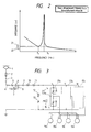
- a second filter reactor 19 and a second filter capacitor 20 connected in series with the reactor 19 are connected across parallel connected inverters 17a, 17b and 17c.
- the reactor 19 and the capacitor 20 constitute a second filter circuit which is connected in parallel to a filter capacitor 16 and circuit constants of the second filter circuit are selected such that a total impedance value of the second filter circuit when looked from the side of the filter capacitor 16 and the control device becomes small at a specific frequency.
- Figure 2 is a graph showing a frequency characteristics of the total impedance of the second filter circuit in which reference numerals 21 and 22 depict a first and second minimum values thereof, respectively.
- I1 I Z2/(Z1+Z2) (4)
- I2 I Z1/(A1+A2) (5)
- the circuit constants of the second filter circuit are set such that the total impedance Z2 of this filter circuit and the filter capacitor 16 takes a value near either of two minimum values existing for a specific frequency or takes two values near minimum values for two frequencies.
- the present invention includes a second filter circuit composed of a second filter reactor and a second filter capacitor connected in series with the former, the second filter circuit being connected in parallel to a first filter capacitor and having circuit constants selected such that a total impedance of this filter circuit and the first filter capacitor becomes small value for a specific frequency. Therefore, the induction problem for the specific frequency can be solved and the minimization of the device can be achieved at low cost, resulting in a minimized equipping space.
Landscapes
- Engineering & Computer Science (AREA)
- Power Engineering (AREA)
- Life Sciences & Earth Sciences (AREA)
- Sustainable Development (AREA)
- Sustainable Energy (AREA)
- Transportation (AREA)
- Mechanical Engineering (AREA)
- Electric Propulsion And Braking For Vehicles (AREA)
- Inverter Devices (AREA)
Applications Claiming Priority (2)
| Application Number | Priority Date | Filing Date | Title |
|---|---|---|---|
| JP11216/88 | 1988-01-21 | ||
| JP63011216A JPH01186101A (ja) | 1988-01-21 | 1988-01-21 | 電気車制御装置 |
Publications (2)
| Publication Number | Publication Date |
|---|---|
| EP0325377A2 true EP0325377A2 (de) | 1989-07-26 |
| EP0325377A3 EP0325377A3 (de) | 1990-06-13 |
Family
ID=11771776
Family Applications (1)
| Application Number | Title | Priority Date | Filing Date |
|---|---|---|---|
| EP89300315A Withdrawn EP0325377A3 (de) | 1988-01-21 | 1989-01-13 | Regelvorrichtung für ein elektrisches Fahrzeug |
Country Status (5)
| Country | Link |
|---|---|
| US (1) | US5113126A (de) |
| EP (1) | EP0325377A3 (de) |
| JP (1) | JPH01186101A (de) |
| AU (1) | AU611987B2 (de) |
| MX (1) | MX173136B (de) |
Families Citing this family (4)
| Publication number | Priority date | Publication date | Assignee | Title |
|---|---|---|---|---|
| JP3046276B2 (ja) * | 1998-05-11 | 2000-05-29 | 三菱電機株式会社 | 電力変換装置 |
| FR2935930B1 (fr) * | 2008-09-12 | 2010-10-29 | Alstom Transport Sa | Chaine de traction electrique pour vehicule ferroviaire. |
| WO2015097868A1 (ja) * | 2013-12-27 | 2015-07-02 | 三菱電機株式会社 | 電力変換装置 |
| DE102017209742A1 (de) * | 2017-06-09 | 2018-12-13 | Robert Bosch Gmbh | Gesteuerte Lastvorrichtung und Herstellungsverfahren für eine gesteuerte Lastvorrichtung |
Family Cites Families (7)
| Publication number | Priority date | Publication date | Assignee | Title |
|---|---|---|---|---|
| US3691439A (en) * | 1971-01-28 | 1972-09-12 | Danfoss As | Control arrangement for a three phase motor with intermediate d.c. regulation |
| US3746963A (en) * | 1971-06-09 | 1973-07-17 | Static Power Inc | Polyphase inverter with d.c. supply |
| SE423771B (sv) * | 1978-07-03 | 1982-05-24 | Asea Ab | Stromriktarutrustning for overforing av energi mellan ett vexelspenningsnet och ett likspenningsnet |
| JPS561773A (en) * | 1979-06-14 | 1981-01-09 | Toyo Electric Mfg Co Ltd | Inverter |
| JPS56110406A (en) * | 1980-01-31 | 1981-09-01 | Mitsubishi Electric Corp | Filter device for electric vehicle |
| JPS57145503A (en) * | 1981-03-04 | 1982-09-08 | Hitachi Ltd | Controlling device of induction motor driven electric motor vehicle |
| DE3585896D1 (de) * | 1984-02-16 | 1992-05-27 | Fanuc Ltd | Hochfrequenzgeraeuschabsorptionsschaltkreis. |
-
1988
- 1988-01-21 JP JP63011216A patent/JPH01186101A/ja active Pending
-
1989
- 1989-01-05 AU AU27748/89A patent/AU611987B2/en not_active Ceased
- 1989-01-13 EP EP89300315A patent/EP0325377A3/de not_active Withdrawn
- 1989-01-20 MX MX014605A patent/MX173136B/es unknown
-
1990
- 1990-08-13 US US07/566,319 patent/US5113126A/en not_active Expired - Fee Related
Also Published As
| Publication number | Publication date |
|---|---|
| AU2774889A (en) | 1989-07-27 |
| EP0325377A3 (de) | 1990-06-13 |
| MX173136B (es) | 1994-02-02 |
| US5113126A (en) | 1992-05-12 |
| JPH01186101A (ja) | 1989-07-25 |
| AU611987B2 (en) | 1991-06-27 |
Similar Documents
| Publication | Publication Date | Title |
|---|---|---|
| KR100963725B1 (ko) | 매트릭스 컨버터 장치 | |
| Steinke | Use of an LC filter to achieve a motor-friendly performance of the PWM voltage source inverter | |
| CA2580104C (en) | Improved power converter with reduced common mode voltage | |
| US6014323A (en) | Multiphase power converter | |
| RU2222092C2 (ru) | Устройство преобразовательной цепи с промежуточной цепью переменного тока | |
| US7336059B2 (en) | System and method for charging and discharging a superconducting coil | |
| JP2807760B2 (ja) | スイッチング電源 | |
| EP0199315B1 (de) | Steuereinrichtung für elektrische Lokomotive mit Wechselstrom/Gleichstrom-Konvertern | |
| US5449993A (en) | Regenerative ac to dc converter | |
| US4431956A (en) | Drive equipment | |
| EP0325377A2 (de) | Regelvorrichtung für ein elektrisches Fahrzeug | |
| EP0081133A1 (de) | Wechselrichter vom Stromtyp | |
| JP3194066B2 (ja) | 電力変換装置 | |
| KR100205269B1 (ko) | 턴 오프 회로 | |
| US5014179A (en) | Transistor load-line controller | |
| JP4005758B2 (ja) | 電気車制御装置 | |
| JP7149881B2 (ja) | 電力変換装置および当該電力変換装置を搭載する鉄道車両 | |
| CN1647339A (zh) | 感应传输电能的装置 | |
| JP3315303B2 (ja) | 電動機制御装置 | |
| SU1286447A1 (ru) | Т говый электропривод транспортного средства с питанием от контактной сети посто нного тока | |
| JPH0446042B2 (de) | ||
| JPH11113102A (ja) | 交直両用電気車制御装置 | |
| JPS63121401A (ja) | 電気車制御装置 | |
| SU955457A2 (ru) | Двух чейковый последовательный инвертор | |
| JPH0833313A (ja) | 電力変換装置のスナバ回路 |
Legal Events
| Date | Code | Title | Description |
|---|---|---|---|
| PUAI | Public reference made under article 153(3) epc to a published international application that has entered the european phase |
Free format text: ORIGINAL CODE: 0009012 |
|
| AK | Designated contracting states |
Kind code of ref document: A2 Designated state(s): ES FR GB IT |
|
| PUAL | Search report despatched |
Free format text: ORIGINAL CODE: 0009013 |
|
| AK | Designated contracting states |
Kind code of ref document: A3 Designated state(s): ES FR GB IT |
|
| 17P | Request for examination filed |
Effective date: 19901116 |
|
| RAP1 | Party data changed (applicant data changed or rights of an application transferred) |
Owner name: MITSUBISHI DENKI KABUSHIKI KAISHA |
|
| 17Q | First examination report despatched |
Effective date: 19920824 |
|
| STAA | Information on the status of an ep patent application or granted ep patent |
Free format text: STATUS: THE APPLICATION IS DEEMED TO BE WITHDRAWN |
|
| 18D | Application deemed to be withdrawn |
Effective date: 19930304 |