EP0325430A2 - Vorrichtung zur Messung der thermischen Konduktivität - Google Patents
Vorrichtung zur Messung der thermischen Konduktivität Download PDFInfo
- Publication number
- EP0325430A2 EP0325430A2 EP89300450A EP89300450A EP0325430A2 EP 0325430 A2 EP0325430 A2 EP 0325430A2 EP 89300450 A EP89300450 A EP 89300450A EP 89300450 A EP89300450 A EP 89300450A EP 0325430 A2 EP0325430 A2 EP 0325430A2
- Authority
- EP
- European Patent Office
- Prior art keywords
- heat
- temperature
- specimen
- measuring
- fluid
- Prior art date
- Legal status (The legal status is an assumption and is not a legal conclusion. Google has not performed a legal analysis and makes no representation as to the accuracy of the status listed.)
- Granted
Links
Images








Classifications
-
- G—PHYSICS
- G01—MEASURING; TESTING
- G01N—INVESTIGATING OR ANALYSING MATERIALS BY DETERMINING THEIR CHEMICAL OR PHYSICAL PROPERTIES
- G01N25/00—Investigating or analyzing materials by the use of thermal means
- G01N25/18—Investigating or analyzing materials by the use of thermal means by investigating thermal conductivity
-
- G—PHYSICS
- G01—MEASURING; TESTING
- G01K—MEASURING TEMPERATURE; MEASURING QUANTITY OF HEAT; THERMALLY-SENSITIVE ELEMENTS NOT OTHERWISE PROVIDED FOR
- G01K17/00—Measuring quantity of heat
- G01K17/06—Measuring quantity of heat conveyed by flowing media, e.g. in heating systems e.g. the quantity of heat in a transporting medium, delivered to or consumed in an expenditure device
- G01K17/08—Measuring quantity of heat conveyed by flowing media, e.g. in heating systems e.g. the quantity of heat in a transporting medium, delivered to or consumed in an expenditure device based upon measurement of temperature difference or of a temperature
- G01K17/20—Measuring quantity of heat conveyed by flowing media, e.g. in heating systems e.g. the quantity of heat in a transporting medium, delivered to or consumed in an expenditure device based upon measurement of temperature difference or of a temperature across a radiating surface, combined with ascertainment of the heat-transmission coefficient
Definitions
- the present invention concerns an apparatus for measuring thermal conductivity used for measuring the thermal conductivity of various materials including thermal insulating and heat reserving materials etc, at a steady-state heat flux.
- thermal conductivity of various materials used as thermal insulating and heat reserving materials is not steady but varies according to their temperature. Their thermal conductivity increases with the rise in their temperature, i.e. it becomes easy for them to conduct heat. This means that if the thermal conductivity of a material which is used at temperatures exceeding 1,000 °C is to be determined, then the measurement of its thermal conductivity must be done by actually heating it up to its service temperature.
- a conventional method for measurement of thermal conductivity is prescribed in ASTM c-177-84 etc. and for example, it is shown in Figure 18.
- This conventional apparatus for measuring thermal conductivity is equipped with a main heater b and an auxiliary heater c arranged respectively in the upper and lower parts of a thermally-insulated enclosure a which heaters produce a steady downward heat flow in the enclosure a, and with a heat flow meter d placed in the upper part of the auxiliary heater c which plate is designed for the measurement of heat flow quantity of the said steady heat flow.
- a device whose heat flow meter d contains a gas flow path of a spiral form through which passes the heat-measuring gas.
- the amount of heat received is calculated from the temperature rise and flow rate of the heat-measuring gas.
- a thermal equilibrium state is created in the enclosure a by means of the main heater b and the auxiliary heater c by arranging a specimen S whose thermal conductivity is to be measured at the center of the enclosure a and by arranging standard heat transfer plates S1 and S2 of known thermal conductivity above and below the specimen.
- the temperature gradient indicated as line B is thus formed through the specimen S and the standard heat transfer plates S1 and S2.
- the thermal conductivity of the specimen S at a particular temperature is calculated from the temperature difference measured by the thermometers e1 and e2 between the upper and lower surfaces of the specimen S in a steady state while maintaining the average inside temperature of the specimen S at the temperature to be measured, and from the amount of heat measured by the heat flow meter d at a steady heat flow, i.e. the amount of heat flow through the specimen S.
- the symbol g represents heaters for the compensation of wall temperature, which controls the surface temperature of the enclosure a so that the temperature gradient of the enclosure is consistent with the temperature gradient in the enclosure a in order to avoid the heat transfer between the enclosure a and its inner space thereby preventing the flow from dispersing from the peripheral surface of the enclosure a.
- thermocouples because the temperature is measured by means of thermocouples, the highest measurable temperature is limitted relatively low.
- the present invention which was made in view of the above facts has for its objective to provide a thermal-conductivity-measuring device capable of obtaining a sufficient accuracy of measurement.
- the present invention concerns an apparatus for measuring thermal conductivity, consisting of:
- Figure 1 is a vertical drawing indicating the general configuration of the apparatus for measuring thermal conductivity in the case here in question.
- the numeral 1 indicates a housing made up of a body 2 with water jacket and of a cover 4 connected to the body 2 with a hinge 3.
- a measuring chamber 8 consisting of a lower and upper disc shaped heat insulators 5 and 6 and a cylindrical lateral heat insulator 7 in which the specimen S is placed.
- a main heater 9 to maintain the measuring chamber 8 at a specified temperature while in the lower heat insulator 5 is embedded a compensating heater 10 to maintain the inside temperature of the lower heat insulator 5 at the same level as that of the heat flow meter (described later).
- electrodes 11 and 12 which pass through the cover 4 of the housing 1 and the body 2.
- the numeral 13 indicates a radiation thermometer to measure the temperature in the measuring chamber 8.
- the inside of the lateral heat insulator 7 which forms the side wall of the measuring chamber 8 is covered with a wall-surface-temperature-compensating plate (call heat compensating plate hereinafter) 14 which is formed in a cylindrical shape with materials having an adequate resistance to heat and an excellent thermal conductivity like, for example, graphite, heat-resistant steel, molybdenum etc.
- a disc shaped heat flow meter 15 At the center in the upper part of the lower heat insulator 5 is arranged a disc shaped heat flow meter 15 around which an annular compensating cooling plate 16 is located.
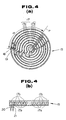
- the heat flow meter 15 as shown in Figure 4 (a) and (b), contains a path 17 for heat-measuring gas for the measurement of the inner received heat, made up of upper and lower plates and a partition plate, each consisting of metal, which is formed like a double spiral with inlet-side and outlet-side paths adjacent to each other.
- An inlet 18 and an outlet 19 for heat-measuring gas are located side by side each at one end of the inlet-side path 17a and the outlet-side path 17b.
- the other ends of the said paths which are located at the center of the heat flow meter 15 are connected to each other.
- the heat-measuring gas introduced from the inlet 18 flows thus toward the center from the periphery in the inlet-side path 17a as indicated by an arrow in the drawing to be led at the center of the heat flow meter 15 toward the outlet-side path 17b through which it flows back to the periphery.
- an inlet pipe 20 and an outlet pipe 21 to lead the heat-measuring gas in and out as indicated by arrows in Figure 1.
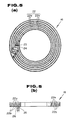
- this compensating cooling plate 16 is built in the same way as the heat flow meter 15 except that it is annular and that the said heat flow meter 15 is placed at its center. That is to say, this compensating cooling plate 16, as indicated in Figure 5 (a) and (b), contains a cooling gas flow path 22 formed with upper and lower plates and a partition plate, each consisting of metal, which is formed like a double spiral with inlet-side 22a and outlet-side 22b paths adjacent to each other.
- An inlet 23 and an outlet 24 for cooling gas are located side by side each at one end of inlet-side and outlet-side paths 22a and 22b located at the innermost periphery of this compensating cooling plate 16 while the other ends of the said paths which are located at the outermost periphery of the compensating cooling plate 16 are connected to each other.
- the cooling gas introduced from the inlet 23, as indicated by an arrow in the drawing flows thus through the inlet-side path 22a from the inner to the outer periphery from where it is led to the outlet-side path 22b, then through the outlet-side path 22b back to the inner periphery and then out of the outlet 24 to the periphery.
- To the above-mentioned inlet 23 and outlet 24 are connected an inlet pipe 25 and an outlet pipe 26 to lead the cooling gas in and out as indicated by arrows in Figure 1.
- the above-mentioned heat-measuring and cooling gases are heated to a specified temperature by gas preheaters 27 and 28 (as shown in Figure 1) embedded in the lower heat insulator 5 and are then led into the heat flow meter 15 and the compensating cooling plate 16, respectively.
- Thermometers (not shown) are provided for measuring the temperature at the inlet 18 and outlet 19 for heat-measuring gas as well as at the inlet 23 and outlet 24 for cooling gas, respectively.
- the above-mentioned heat flow meter 15 like the one d used in the conventional apparatus for measuring thermal conductivity, is intended to measure the temperature at the inlet 18 and outlet 19 and thereby measure the received heat by the heat-measuring gas, i.e. the transmitted heat through the specimen S, on the basis of the temperature difference between the inlet 18 and the outlet 19 and the gas flow at the inlet and the outlet 19.
- the compensating cooling plate 16 placed around the periphery of the heat flow meter 15, on the other hand is intended to prevent the outward flow of heat from the heat flow meter 15 by maintaining its temperature at the same level as the heat flow meter 15 and is intended to control the heat flow which flows from the measuring chamber 8 to the heat flow meter 15 to become lateral flow.
- a heat-measuring plate 29 On top of the above-mentioned heat flow meter 15 and compensating cooling plate 16 is arranged a heat-measuring plate 29 on top of which is located a disc shaped standard heat transfer plate 30 of a material with a known thermal conductivity.
- This standard heat transfer plate 30 which, like the above-mentioned standard heat transfer plates s1 and s2 used in a conventional device, is intended to maintain the temperature of the specimen S at a high level and the surface temperature of the heat flow meter 15 at a low level and which is at the same time intended to verify and correct a measured heat flow value determined from the temperature difference and known thermal conductivity by measuring the upper and lower surface temperature of the heat transfer plate 30 with a thermometer (not shown) inserted in the heat-measuring plate 29 and a thermocouple 33 inserted in the lower heat-measuring plate described later, is a layer-built structure made of laminar heat insulator 30a such as formed plate of carbon fiber densely wound in a spiral form.
- this standard heat transfer plate 30 As its laminar heat insulator 30a has a wound form, this standard heat transfer plate 30 has a thermal conductivity 2 to 3 times higher in the direction of thickness than in the direction of diameter. This means that this standard heat transfer plate 30 transfers heat easily in the direction of thickness but with difficulty in the direction of diameter.
- thermocouples 33 and 34 are Inserted in the lower 31 and upper 32 heat-measuring plates which measure the temperature of the lower and upper surfaces of the specimen S.
- the numeral 35 indicates a cylindrical heat insulator placed outside the standard heat transfer plate 30.
- thermocouple 34 into the upper measuring plate 32.
- the device here under review in which the inside of the measuring chamber 8 is provided with the heat compensating plate 14 of a highly heat-conductive material extending therein, however, permits such an amount of heat as may be lost by the effect of heat conduction to be conducted through the heat compensating plate 14 to the lateral heat insulator 7 so that the heat radiation from the specimen S and the standard heat transfer plate 30 to their peripheries can be avoided effectively.
- the heat compensating plate 14 may not be disposed to cover the whole part of the chamber 8 above the specimen. It is sufficient that the heat compensating plate 14 protrudes in the measuring chamber 8 from the peripheral part of the specimen.
- the actual distance z1 of the heat compensating plate 14 is determined by making a calculation taking into account the whole range of possible lateral heat flows.
- the device in the first preferred embodiment employs the heat flow meter 15 with the gas flow path 17 formed like a double spiral, the surface temperature of the heat flow meter never becomes uneven which makes it possible to obtain adequate accuracy of measurement.
- the average temperatures of the measuring gases passing through the paths which are adjacent to each other are all the same and hence the surface temperature of the heat flow meter, too, is the same so that ultimately the heat flow meter 15 as a whole has an almost even temperature.
- annular compensating cooling plate 16 around the heat flow meter 15 which like the heat flow meter 15 also maintains an even temperature all over the surface.
- the standard heat transfer plate 30 employed has a thermal conductivity which is small in the axial direction than in the radial direction due to the particular spiral form of the laminar heat insulator 30a, the steady transmitted heat through the specimen S flows only downward through the standard heat transfer plate 30 and is restricted from flowing sidewards. Consequently the loss of heat flowing sideward from the standard heat transfer plate 30 will naturally be minimized.
- the apparatus for measuring thermal conductivity here under review is capable of exactly measuring the transmitted heat Q and hence improving the accuracy of measurement.
- the heat lost from the lateral heat insulator 7 and the transmitted heat from the heat compensating plate 14 to the heat insulator 7 are both constant in the direction of thickness of the specimen S so that the thickness of the heat compensating plate 14 is assumed to be constant which in normal cases proves to be sufficiently effective.
- the above-mentioned heat loss Q1 and the transmitted heat Q2 are not constant in the direction of thickness of the specimen S. Consequently, if we make the transmitted heat to all the parts of the lateral heat insulator 7 vary according to the amount lost by making the thickness of the heat compensating plate 14 gradually smaller from the upper to the lower part, then we can obtain a higher accuracy of measurement.
- This temperature difference ⁇ ⁇ is a constant which is proportional to ⁇ l in case the temperature gradient of the specimen S (i.e. degree of change between the upper ⁇ 1 and lower ⁇ 2 surface temperatures) is linear (all the examples of calculations hitherto introduced are such cases).
- the inside of the specimen S and the heat compensating plate 14 which is in contact with it can maintain one and the same temperature all over the surface respectively and, as a result, we can obtain an accuracy of measurement which is much better than the one obtained in that above-mentioned case in which the thickness of the heat compensating plate 14 is constant.
- the gas path 17 which is formed into a double spiral in the heat flow meter 15 with one part almost concentric and the other part bent inward, it may be of course realized in the form of a perfect spiral.
- the inlet 18 and outlet 19 for gas are installed on the outer periphery side, they may just as well be installed at the center of the heat flow meter 15 so as to let the measuring gas flow from the center to the outer periphery and then back to the center.
- the laminar heat insulator 30a constituting the standard heat transfer plate 30
- any other material will do as long as it is has heat-insulating and heat-resistant properties.
- a laminar heat insulator 30a such as, for example, alumina silica paper as one of the two laminas and a highly heat transfer material such as, for example, metal plate 30b as the other lamina
- a highly heat transfer material such as, for example, metal plate 30b
- a combination of graphite heat insulator and graphite foil multi-layer winding proves to be effective for use at high temperatures.
- the standard heat transfer plate 30 is provided only on the lower surface of the specimen 30.
- the apparatus for measuring thermal conductivity under review in the second preferred embodiment is set up in such a way that the compensating heater 10 referred to in the executed the first preferred embodiment is omitted and the heat compensating plate 50 is provided in the lower heat insulator 5.
- the heat compensating plate 50 like the heat flow meter 15 and the compensating cooling plate 16, contains a path formed into a spiral (not shown) for water which as a heat-measuring fluid is supplied by a circulating system to the heat-measuring plate 15, the compensating cooling plate 16 and the heat compensating plate 50.
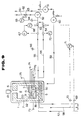
- This circulating system which is made up of the main components as illustrated in Figure 9 including a circulating pump (means for pressurized feed) 51 and a cooler (means for temperature adjustment) 52 installed at the pressure side of the said circulating pump 51, is designed to circulate water for heat transfer by pumping the water with the circulating pump 51 to the cooler 52 where the water is cooled down to a specified temperature before it is led through feed pipes 55 and 56 branched off via flow-control valves 53 and 54 to and then through heat flow meter 15 and the compensating cooling plate 16, as illustrated by arrows and broken lines in Figure 8, whereupon it passes through communicating tubes 57 and 58 (illustrated as pipe routes in Figure 9) provided in the lower heat insulator 5 and then through the above-mentioned heat compensating plate 50 and then is pumped through a return pipe 59 and a tank 60 back to the cooler 52.
- communicating tubes 57 and 58 illustrated as pipe routes in Figure 9
- a feed pipe 61 equipped with a flow-control valve 63 for primary cooling water and a return pipe 62.
- the degree of opening of this flow-control valve 63 is adjusted by the temperature indicator/regulator 65 according to the temperature at the outlet of the cooler 52 thereby making it possible to maintain this temperature at a certain level (for example 50°C).
- the temperature of the water supplied to the heat flow meter 15 through the feed pipe 55 is measured by a thermocouple 66 while the flow rate is regulated by adjustment of the flow-control valve 53. This flow rate is adjusted so that the temperature rise when the water passes through the heat flow meter 15 is a certain value (for example 5°C or so). Once it is adjusted, the flow rate is maintained constant by the flow-control valve which is automatically controlled by a flow meter 67 and a flow-control gauge 68.
- the quantity of the water supplied through the feed pipe 56 to the compensating cooling plate 16 is controlled by the above-mentioned flow-control valve 54 which is adjusted by a temperature indicator/regulator 71 according to the outlet temperature of the heat flow meter 15 and that of the compensating cooling plate 16 measured by thermocouples 69 and 70 so that the said outlet temperatures may be equal to each other while the quantity of flow is indicated by a flow meter 72.
- thermocouples 73, 74 and 75 respectively while the inside and the outside of the heat insulator 35 are equipped with 2 pairs of thermocouples adjacent to each other, i.e. altogether four thermocouples 76, respectively.
- start the circulating pump 51 of the circulating system maintain the water temperature at the outlet of the cooler 52 constant, for example, at 50°C and supply water through the feed pipes 55 and 56 to the heat flow meter 15 and the compensating cooling plate 16 of specified flow rates respectively.
- the water flow rate to the compensating cooling plate 16 is automatically adjusted by the thermocouples 69 and 70, the temperature indicator/regulator 71 and the flow-control valve 54 so that the water temperature at the outlet of the compensating cooling plate 16 is equal to the water temperature at the outlet of the heat flow meter 15 (i.e. 55°C or so).
- the temperature of the heat flow meter 15 and that of the compensating cooling plate are maintained at the same level while water with a temperature of about 55°C flows into the heat compensating plate 50 from both the heat flow measuring plate 15 and compensating cooling plate 16 thereby causing this heat compensating plate to maintain the said outlet temperature.
- the specimen S and the water as heat-measuring fluid measure the temperature on the upper (front) surface 1 and the lower (back) surface 2 of the specimen S with the thermocouples 75 and 74. Also, accurately measure the temperature of the water flowing through the heat flow meter 15 at the inlet and the outlet with the thermocouples 66 and 69 as well as the flow rate with the flow meter 67 to find the received heat by the heat flow meter 15, i.e. the transmitted heat Q through the specimen S. Also, find the thermal conductivity La at the set temperature of the specimen S with the above-mentioned equation (1) from the heat flow Q, the upper ⁇ 1 and lower ⁇ 2 surface temperatures of the specimen S and the distance z from the surface thereof. In this case the effective area A of the specimen S is equal to the area of the heat flow meter 15.
- a measurement error can be considered due to the heat radiation to the outer part from the heat insulator 35 placed around the specimen S. we can, however, easily correct the measured value and thus further improve the accuracy of measurement by measuring the inside temperature of the insulator 35 with the thermocouples 76 and calculating the amount of heat lost from the heat insulator 35.
- the thickness of the lower heat insulator 5 can be made large enough to avoid the risk of a measurement error, and the heat compensating plate 50 may be omitted. If in this case the bodies of water flowing out of the heat flow meter 15 and the compensating cooling plate 16 are made to meet through a duct which in return is made to meander in the lower heat insulator 5, then one can get an equivalent effect as in the case in which the heat compensating plate 50 is provided.
- the temperature control system is made up of one unit of the cooler 52 and the circulating water is maintained at a constant temperature by controlling the quantity of the primary cooling water supplied to this cooler 52. It is nevertheless quite possible to set up the temperature control system in other ways, for example, as illustrated in Figure 10.
- it is not necessary to exactly control the water temperature at the outlet of the cooler 81 (hence the flow- control valve referred to in the above-mentioned case may be omitted), but it suffices to control the water temperature at the outlet of the heater 83 only by controlling the output of the heater 82. Setting up the temperature control system 80 in this way makes it possible to control the circulating water temperature more exactly and more easily.
- heat-measuring fluid not only just water but also oils or gases may be used.
- oils or gases may be used for heat-measuring fluid.
- a blower in place of the circulating pump and to use flow-control valves and flow meters for gases.
- the device is realized as an upright type, it is also quite possible to realize the device as a horizontal type which is set up in such a way that the specimen S is placed in a vertical position in the measuring chamber.
- the device according to the third preferred embodiment differs from the one according to the second preferred embodiment in that the standard heat transfer plate 30 is omitted and the specimen S is placed in its position, that found the specimen S is provided a enclosure 100 in place of the heat insulator 35 and that the enclosure 100 and the upper side of the specimen S are covered with a heat transfer plate 101.
- the enclosure 100 which is of a cylindrical shape, is arranged in such a way that its lower side makes good contact with the upper side of the compensating cooling plate 16 while its outside makes good contact with the inside of the lateral heat insulator 7.
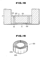
- This enclosure 100 as shown in Figure 12 consists of thin layers of heat insulator 100a made of, for example, formed sheets of carbon fiber densely wound into a spiral of a multi-layer structure. Due to the particular form obtained by winding the thin layer of heat insulator 100a as described above, this enclosure 100 has a thermal conductivity in the axial direction (direction of thickness) substantially (for example about 10 times) larger than that in the radial direction. This means that the enclosure 100 transfers heat easily in the axial direction but with difficulty in the radial direction.
- the thermal conductivity of the enclosure 100 in the axial direction is substantially (for example about 5 times) larger than that of the above-mentioned lateral heat insulator 7. It is desirable to make the said conductivity in the axial direction substantially larger even than the expected thermal conductivity of the specimen S.
- a lower heat-measuring plate 102 Inside this enclosure 100 is arranged a lower heat-measuring plate 102 with its lower surface making good contact with the upper surface of the heat flow meter 15 and with the compensating cooling plate 16 while on its upper side is placed the specimen S whose thermal conductivity is to be measured and on the upper surface of which is arranged the above-mentioned heat transfer plate 101.
- This heat transfer plate 101 covers the upper surface of the specimen S and that of the enclosure 100 to maintain the upper surface temperature of the specimen S at the same level as that of the enclosure 100.
- thermocouples (not shown) for the measurement of the upper and lower temperatures of the specimen S respectively are inserted in the above-mentioned lower heat measuring plate 102 and the heat transfer plate 101.
- the heat transfer plate 101 which is illustrated in Figure 11 as one sheet, may as well be divided into two sections, if necessary, one covering the upper surface of the specimen S and the other one covering that of the enclosure 100.
- the enclosure 100 is arranged inside the measuring chamber 8 while the specimen S is placed inside the said enclosure 100 whose thermal conductivity is substantially larger (i.e. which conducts heat more easily) in the axial direction than in the radial direction so that in this enclosure 100, the heat flow, as illustrated by arrows in Figure 14 (a), mainly takes place in the axial direction, i.e. downward while the flow in the radial direction, i.e. side way flow, is restricted. Since a heat insulator 7 is provided outside the enclosure, the flow of heat from the enclosure 100 to the heat insulator 7 is restricted by this also suppressing the heat flow in the axial direction.
- the inside temperature curve in such a case is generally extremely similar even among materials of basically different thermal conductivity values. Consequently, in the case when the temperature at point C on the upper surface of the enclosure 100 is T1, i.e. the same as at the point A and the temperature at point D on the lower surface of the enclosure in the same horizontal section as the lower surface of the specimen S is T2, i.e. the same as at point B, then the inside temperature of the enclosure 100 will assume a characteristics as indicated by the temperature curve Y drawn with a dotted line in Figure 14 (b). These temperature curves X and Y turn out to be almost identical with each others, i.e. both inside temperatures are almost identical with other at any point in the same horizontal section. This fact becomes even more obvious when the thermal conductivity of the enclosure 100 is larger than the expected thermal conductivity of the specimen S. Consequently it is desirable to set the thermal conductivity of the enclosure 100 in the axial direction correspondingly larger.
- heat insulator 103 of a cylindrical form inside the enclosure 100.
- this heat insulator 103 may be of a normal type or be set up in the same way as the above- mentioned heat-flow-compensating cylinder 100.
- by additionally providing the heat insulator 103 inside the enclosure 100 we can reduce further the influence of an eventual non-negligible difference in the temperature curves X and Y shown in Figure 14 (b).
- the enclosure 100 is set up as a spiral made by winding thin strips of the heat insulator 100a with while a formed sheet of carbon fiber employed as the heat insulator 100a
- the configuration of the enclosure is not limited to the type mentioned above only but one may as well employ the enclosure 100 made by winding two thin strips of sheets of different materials one laid on top of the other.
- the laminar heat insulator 100a such as, for example, alumina silica paper as one of the two laminas and a highly heat-conductive material such as, for example, a metal plate 100b as the other lamina
- a combination between graphite heat insulator and graphite foil multi-layer winding proves to be effective for use at high temperatures.
- one may as well form the enclosure using a material with a property such that its thermal conductivity varies according to the direction rather than using the winding of lamina as described above.
- the device according to the fourth preferred embodiment consists of the second furnace whose inside is divided by a lamina 120 into the measuring chamber 8 in which the specimen S is placed and a vacuum chamber 121 in which a vacuum can be formed.
- the lamina 120 which is of a disc shape is installed with its periphery inserted between annular flanges 122 and 123 fixed to the inner surface of the housing 1 while between the flange 122 and the lamina 120 is provided a seal 124 for maintaining a vacuum formed in the vacuum chamber 121.
- This lamina 120 which is made of a metal plate with an excellent thermal conductivity (for example stainless steel plate) and whose thickness is adequately thin (for example about 0.3 mm) must have an adequate strength to resist the pressure difference between the vacuum chamber 121 and the measuring chamber 8.
- a lower heat-measuring plate 31 On the upper surface of the standard heat transfer plate 30 is arranged a lower heat-measuring plate 31 on which is arranged the specimen S whose thermal conductivity is to be measured and on top of which is arranged an upper heat-measuring plate 32.
- the disc shaped heat- measuring plate 29 which is attached fast to the lower side of the lamina 120 and at the center of the lower side of which is arranged the heat flow meter 15 around which is located the compensating cooling plate 16 which is supported by a column 125 resting on the bottom of the furnace 1 while the above-mentioned heat-measuring plate 15 is supported by a fixture 126 fixed to the compensating cooling plate 16.
- a reflective board 127 which covers the lower side of the heat flow meter 15.
- the reflective board 127 is made of a metal with an excellent thermal conductivity with its upper surface (surface facing the heat flow meter 15) finished with a mirror surface grade of metallic luster with an extremely small radiation coefficient.
- the heat radiation can be reduced to an almost negligible degree when conducting measurements with the vacuum chamber 121 kept under vacuum so that an adequate accuracy of measurement can be obtained.
- the heat flow meter 15 since in this device the heat flow meter 15 is arranged in the vacuum chamber 121 the heat lost from this heat flow meter 15 to the environment occurs almost exclusively through radiation without a large loss of heat occurring as has been the case until now by heat transfer and convection. Furthermore, the reflective board itself which is arranged on the lower side of the heat flow meter 15 is also intended to reduce radiation heat loss from the compensating cooling plate 16 so that the compensating cooling plate 16 assumes a temperature also equivalent to that of the heat flow meter 15.
- a possible heat loss other than the one by radiation is the heat transfer from the heat heat flow meter 15 to the compensating cooling plate 16 through the fixture 126 supporting the heat flow meter 15.
- the heat flow through the fixture 126 can be almost neglected since almost the same temperature is maintained between the heat flow meter 15 and the compensating cooling plate 16.
- the heat transfer takes place from the compensating cooling plate 16 to the environment thereby causing a temperature difference between the compensating cooling plate 16 and the heat flow meter 15.
- the transmitted heat can be almost neglected since the thickness of the lamina 120 is sufficiently small.
- the heat transmitted from the compensating cooling plate 16 to the environment through the lamina 120 is proportional to the area of heat transfer A1 obtained as a product of the length of the periphery of the compensating cooling plate 16 multiplied by the thickness of lamina 120.
- This value ⁇ becomes considerably large when the value z is substantially smaller than the value D.
- ⁇ is equal to about 417.
- the transmitted heat to the outer periphery through the lamina 120 is of the order of 1/100 of that in the direction of thickness and as such may be said to be nearly negligible.
- the vacuum chamber 121 which is evacuated gives rise to the development of a pressure difference between the measuring chamber 8 and the vacuum chamber 121 which is then exerted on the lamina 120.
- the lamina 120 itself which has an adequate strength, however, is fixed by means of the flanges 122 and 123 at its periphery and is supported by the column 125 through the compensating cooling plate 16.
- the lamina 120 is pressed fast against the heat-measuring plate 29 while the upper heat-measuring plate 32, the specimen S and the lower heat-measuring plate 31 and the standard heat transfer plate 30 are all pressed fast against the lamina 120, too, so that the development of a gap between them is naturally avoided and hence the heat transfer between them is maintained in a favorable condition. In this respect, too, the accuracy of measurement can be improved.
- the standard heat transfer plate installed on the upper side of the lamina 120 may, if there is no particular need for it, be omitted, thereby causing the lower heat-measuring plate 31 to stick fast to the upper side of the lamina 120.
- any other material may as well be used as long as such material can be machined to an adequate thinness and has a good thermal conductivity.
Landscapes
- Physics & Mathematics (AREA)
- Chemical & Material Sciences (AREA)
- General Physics & Mathematics (AREA)
- Life Sciences & Earth Sciences (AREA)
- Combustion & Propulsion (AREA)
- Health & Medical Sciences (AREA)
- Engineering & Computer Science (AREA)
- Analytical Chemistry (AREA)
- Biochemistry (AREA)
- General Health & Medical Sciences (AREA)
- Immunology (AREA)
- Pathology (AREA)
- Investigating Or Analyzing Materials Using Thermal Means (AREA)
Applications Claiming Priority (12)
| Application Number | Priority Date | Filing Date | Title |
|---|---|---|---|
| JP431088U JPH01110359U (de) | 1988-01-18 | 1988-01-18 | |
| JP7804/88 | 1988-01-18 | ||
| JP780388A JPH0625742B2 (ja) | 1988-01-18 | 1988-01-18 | 熱伝導率測定装置 |
| JP780488A JPH0750051B2 (ja) | 1988-01-18 | 1988-01-18 | 熱伝導率測定装置 |
| JP4310/88U | 1988-01-18 | ||
| JP7803/88 | 1988-01-18 | ||
| JP18172/88 | 1988-01-28 | ||
| JP1817288A JPH0750052B2 (ja) | 1988-01-28 | 1988-01-28 | 熱伝導率測定装置 |
| JP2110088U JPH0613484Y2 (ja) | 1988-02-19 | 1988-02-19 | 熱伝導率測定装置 |
| JP21100/88U | 1988-02-19 | ||
| JP21101/88U | 1988-02-19 | ||
| JP2110188U JPH0613485Y2 (ja) | 1988-02-19 | 1988-02-19 | 熱伝導率測定装置 |
Publications (3)
| Publication Number | Publication Date |
|---|---|
| EP0325430A2 true EP0325430A2 (de) | 1989-07-26 |
| EP0325430A3 EP0325430A3 (de) | 1991-10-23 |
| EP0325430B1 EP0325430B1 (de) | 1996-05-01 |
Family
ID=27547829
Family Applications (1)
| Application Number | Title | Priority Date | Filing Date |
|---|---|---|---|
| EP89300450A Expired - Lifetime EP0325430B1 (de) | 1988-01-18 | 1989-01-18 | Vorrichtung zur Messung der thermischen Konduktivität |
Country Status (3)
| Country | Link |
|---|---|
| US (1) | US4929089A (de) |
| EP (1) | EP0325430B1 (de) |
| DE (1) | DE68926356T2 (de) |
Cited By (6)
| Publication number | Priority date | Publication date | Assignee | Title |
|---|---|---|---|---|
| FR2683908A1 (fr) * | 1991-11-14 | 1993-05-21 | Aerospatiale | Procede de mesure de la conductivite thermique d'un materiau. |
| FR2745636A1 (fr) * | 1996-03-04 | 1997-09-05 | Aerospatiale | Procede pour determiner la conductivite thermique d'un materiau a haute temperature et conductimetre pour la mise en oeuvre de ce procede |
| US6142662A (en) * | 1998-06-16 | 2000-11-07 | New Jersey Institute Of Technology | Apparatus and method for simultaneously determining thermal conductivity and thermal contact resistance |
| RU2189581C2 (ru) * | 2000-12-14 | 2002-09-20 | Уральский электрохимический комбинат | Способ определения эффективной теплопроводности порошковых материалов |
| KR20140005074A (ko) * | 2012-07-03 | 2014-01-14 | 한국전자통신연구원 | 열전도도 측정 장치 및 그 측정 방법 |
| CN114485998A (zh) * | 2020-11-13 | 2022-05-13 | 北京华卓精科科技股份有限公司 | 散热量测量方法及装置 |
Families Citing this family (16)
| Publication number | Priority date | Publication date | Assignee | Title |
|---|---|---|---|---|
| US5297868A (en) * | 1993-06-23 | 1994-03-29 | At&T Bell Laboratories | Measuring thermal conductivity and apparatus therefor |
| US6241383B1 (en) * | 1998-03-25 | 2001-06-05 | Murray F. Feller | Heat exchanger maintenance monitor apparatus and method |
| US6331075B1 (en) | 1998-05-01 | 2001-12-18 | Administrator, National Aeronautics And Space Administration | Device and method for measuring thermal conductivity of thin films |
| US6183128B1 (en) * | 1999-05-03 | 2001-02-06 | Westvaco Corporation | Apparatus and method for determining paperboard thermal conductivity |
| JP3444252B2 (ja) * | 1999-12-17 | 2003-09-08 | 株式会社島津製作所 | 熱伝導度検出器 |
| US6487866B1 (en) * | 2000-07-10 | 2002-12-03 | The United States Of America As Represented By The National Aeronautics & Space Administration | Multipurpose thermal insulation test apparatus |
| US6742926B1 (en) * | 2000-07-10 | 2004-06-01 | The United States Of America As Represented By The Administrator Of The National Aeronautics And Space Administration | Methods of testing thermal insulation and associated test apparatus |
| JP2002131257A (ja) * | 2000-10-26 | 2002-05-09 | Nisshinbo Ind Inc | 熱伝導率測定方法、測定装置及び断熱材の製造方法 |
| CN2706759Y (zh) * | 2003-12-03 | 2005-06-29 | 鸿富锦精密工业(深圳)有限公司 | 热流产生装置 |
| CN2672651Y (zh) * | 2003-12-19 | 2005-01-19 | 鸿富锦精密工业(深圳)有限公司 | 热流产生装置 |
| TWM249053U (en) * | 2003-12-26 | 2004-11-01 | Hon Hai Prec Ind Co Ltd | Heat generating device |
| TWM249412U (en) * | 2003-12-26 | 2004-11-01 | Hon Hai Prec Ind Co Ltd | Heat generating device |
| GB0617451D0 (de) | 2006-09-05 | 2006-10-18 | Medical Prediction Ltd | |
| US7559689B2 (en) * | 2007-02-12 | 2009-07-14 | Honda Motor Co., Ltd. | Attaching in situ thermal management equipment to high pressure storage tanks for industrial gases |
| GB0815694D0 (en) * | 2008-08-28 | 2008-10-08 | Cambridge Tempreature Concepts | Tempreature sensor structure |
| WO2010064196A2 (es) * | 2008-12-02 | 2010-06-10 | Universidad Del Valle | Dispositivo para la determinación de la conductividad térmica y procesos de aplicación del mismo |
Family Cites Families (9)
| Publication number | Priority date | Publication date | Assignee | Title |
|---|---|---|---|---|
| US2214344A (en) * | 1935-10-24 | 1940-09-10 | John J Daly | Beverage barrel cooler |
| US2690653A (en) * | 1952-08-14 | 1954-10-05 | Dole Refrigerating Co | Stamped plate |
| US3263485A (en) * | 1964-01-30 | 1966-08-02 | Minnesota Mining & Mfg | Apparatus for determining thermal conductivity |
| US3266290A (en) * | 1964-03-19 | 1966-08-16 | American Cyanamid Co | Measurement of thermal conductivity |
| US3279239A (en) * | 1964-04-29 | 1966-10-18 | Dow Chemical Co | Method and apparatus for measurement of thermal conductivity |
| FR2245247A5 (en) * | 1973-09-26 | 1975-04-18 | Ctre Ex Etu Batiment | Measurement of thermal conductivity and diffusivity - is obtained from recording of thermal shock effects on isolating materials |
| PL139300B1 (en) * | 1983-04-27 | 1987-01-31 | Pan Ct Badan Molekularnych I M | Method of determination of thermal conductivity and heat storage capacity of materials and apparatus therefor |
| US4553852A (en) * | 1983-12-07 | 1985-11-19 | W. R. Grace & Co. | Apparatus and method for heat flow measurement |
| US4812050A (en) * | 1985-05-28 | 1989-03-14 | The United States Of America As Represented By The Secretary Of The Navy | Method for calibrating a heat flux gauge |
-
1989
- 1989-01-18 US US07/298,052 patent/US4929089A/en not_active Expired - Fee Related
- 1989-01-18 EP EP89300450A patent/EP0325430B1/de not_active Expired - Lifetime
- 1989-01-18 DE DE68926356T patent/DE68926356T2/de not_active Expired - Fee Related
Cited By (6)
| Publication number | Priority date | Publication date | Assignee | Title |
|---|---|---|---|---|
| FR2683908A1 (fr) * | 1991-11-14 | 1993-05-21 | Aerospatiale | Procede de mesure de la conductivite thermique d'un materiau. |
| FR2745636A1 (fr) * | 1996-03-04 | 1997-09-05 | Aerospatiale | Procede pour determiner la conductivite thermique d'un materiau a haute temperature et conductimetre pour la mise en oeuvre de ce procede |
| US6142662A (en) * | 1998-06-16 | 2000-11-07 | New Jersey Institute Of Technology | Apparatus and method for simultaneously determining thermal conductivity and thermal contact resistance |
| RU2189581C2 (ru) * | 2000-12-14 | 2002-09-20 | Уральский электрохимический комбинат | Способ определения эффективной теплопроводности порошковых материалов |
| KR20140005074A (ko) * | 2012-07-03 | 2014-01-14 | 한국전자통신연구원 | 열전도도 측정 장치 및 그 측정 방법 |
| CN114485998A (zh) * | 2020-11-13 | 2022-05-13 | 北京华卓精科科技股份有限公司 | 散热量测量方法及装置 |
Also Published As
| Publication number | Publication date |
|---|---|
| EP0325430A3 (de) | 1991-10-23 |
| EP0325430B1 (de) | 1996-05-01 |
| DE68926356T2 (de) | 1996-11-14 |
| DE68926356D1 (de) | 1996-06-05 |
| US4929089A (en) | 1990-05-29 |
Similar Documents
| Publication | Publication Date | Title |
|---|---|---|
| EP0325430B1 (de) | Vorrichtung zur Messung der thermischen Konduktivität | |
| EP0370162B1 (de) | Verfahren und Vorrichtung zum Messen und Steuern eines Flüssigkeitsdurchflusses | |
| CN102640070B (zh) | 压力式流量控制装置 | |
| KR101303653B1 (ko) | 유체의 유량을 제어하기 위한 열 질량유량 컨트롤러 및 열 질량유량 컨트롤러에서 열 사이포닝을 보상하기 위한 방법 | |
| KR100705375B1 (ko) | 온도센서 교정장치 | |
| US1902427A (en) | Flow meter | |
| US5547282A (en) | Calorimetric measuring apparatus | |
| EP1477781A1 (de) | Massendurchflussmesser | |
| JP2006145446A (ja) | 熱伝導率測定装置及び熱伝導率の測定方法 | |
| KR102453893B1 (ko) | 항온조를 이용한 온도계 교정 장치 | |
| US4339949A (en) | Process and apparatus for the thermal measurement of mass flow | |
| Levy et al. | Heat transfer to water in thin rectangular channels | |
| Hallman | Experimental Study of Combined Forced and Free-laminar Convection in a Vertical Tube | |
| US6572263B1 (en) | Dry calorimeter | |
| EP3070444A1 (de) | Oberflächentemperaturmessfühler | |
| KR102453896B1 (ko) | 항온조를 이용한 온도계 교정 장치의 교정 용기 | |
| EP0325441B1 (de) | Verfahren zur Messung der thermischen Konduktivität | |
| US4978229A (en) | Method and apparatus for testing thermal conductivity | |
| JP3315368B2 (ja) | 熱伝導率測定装置及び測定方法 | |
| US5641231A (en) | Temperature monitoring apparatus equipped with gas chamber for converting temperature to gas pressure | |
| JP2638994B2 (ja) | 熱伝導率測定方法 | |
| JPH01193635A (ja) | 熱伝導率測定装置 | |
| Byrd et al. | Design, manufacture, and calibration of infrared radiometric blackbody sources | |
| JPH0613484Y2 (ja) | 熱伝導率測定装置 | |
| CN223526215U (zh) | 一种用于测试液态金属中材料腐蚀速率的装置 |
Legal Events
| Date | Code | Title | Description |
|---|---|---|---|
| PUAI | Public reference made under article 153(3) epc to a published international application that has entered the european phase |
Free format text: ORIGINAL CODE: 0009012 |
|
| AK | Designated contracting states |
Kind code of ref document: A2 Designated state(s): DE FR GB IT |
|
| PUAL | Search report despatched |
Free format text: ORIGINAL CODE: 0009013 |
|
| AK | Designated contracting states |
Kind code of ref document: A3 Designated state(s): DE FR GB IT |
|
| 17P | Request for examination filed |
Effective date: 19920107 |
|
| 17Q | First examination report despatched |
Effective date: 19930910 |
|
| GRAH | Despatch of communication of intention to grant a patent |
Free format text: ORIGINAL CODE: EPIDOS IGRA |
|
| GRAA | (expected) grant |
Free format text: ORIGINAL CODE: 0009210 |
|
| AK | Designated contracting states |
Kind code of ref document: B1 Designated state(s): DE FR GB IT |
|
| PG25 | Lapsed in a contracting state [announced via postgrant information from national office to epo] |
Ref country code: IT Free format text: LAPSE BECAUSE OF FAILURE TO SUBMIT A TRANSLATION OF THE DESCRIPTION OR TO PAY THE FEE WITHIN THE PRE;WARNING: LAPSES OF ITALIAN PATENTS WITH EFFECTIVE DATE BEFORE 2007 MAY HAVE OCCURRED AT ANY TIME BEFORE 2007. THE CORRECT EFFECTIVE DATE MAY BE DIFFERENT FROM THE ONE RECORDED.SCRIBED TIME-LIMIT Effective date: 19960501 |
|
| REF | Corresponds to: |
Ref document number: 68926356 Country of ref document: DE Date of ref document: 19960605 |
|
| ET | Fr: translation filed | ||
| PLBE | No opposition filed within time limit |
Free format text: ORIGINAL CODE: 0009261 |
|
| STAA | Information on the status of an ep patent application or granted ep patent |
Free format text: STATUS: NO OPPOSITION FILED WITHIN TIME LIMIT |
|
| 26N | No opposition filed | ||
| PGFP | Annual fee paid to national office [announced via postgrant information from national office to epo] |
Ref country code: FR Payment date: 19980109 Year of fee payment: 10 Ref country code: GB Payment date: 19980109 Year of fee payment: 10 |
|
| PGFP | Annual fee paid to national office [announced via postgrant information from national office to epo] |
Ref country code: DE Payment date: 19980123 Year of fee payment: 10 |
|
| PG25 | Lapsed in a contracting state [announced via postgrant information from national office to epo] |
Ref country code: GB Free format text: LAPSE BECAUSE OF NON-PAYMENT OF DUE FEES Effective date: 19990118 |
|
| GBPC | Gb: european patent ceased through non-payment of renewal fee |
Effective date: 19990118 |
|
| PG25 | Lapsed in a contracting state [announced via postgrant information from national office to epo] |
Ref country code: FR Free format text: LAPSE BECAUSE OF NON-PAYMENT OF DUE FEES Effective date: 19990930 |
|
| PG25 | Lapsed in a contracting state [announced via postgrant information from national office to epo] |
Ref country code: DE Free format text: LAPSE BECAUSE OF NON-PAYMENT OF DUE FEES Effective date: 19991103 |
|
| REG | Reference to a national code |
Ref country code: FR Ref legal event code: ST |