EP0325433B1 - Système de commande pour transmission-réception sans fil - Google Patents
Système de commande pour transmission-réception sans fil Download PDFInfo
- Publication number
- EP0325433B1 EP0325433B1 EP89300457A EP89300457A EP0325433B1 EP 0325433 B1 EP0325433 B1 EP 0325433B1 EP 89300457 A EP89300457 A EP 89300457A EP 89300457 A EP89300457 A EP 89300457A EP 0325433 B1 EP0325433 B1 EP 0325433B1
- Authority
- EP
- European Patent Office
- Prior art keywords
- code
- receiver
- data
- wireless
- transmitters
- Prior art date
- Legal status (The legal status is an assumption and is not a legal conclusion. Google has not performed a legal analysis and makes no representation as to the accuracy of the status listed.)
- Expired - Lifetime
Links
Images









Classifications
-
- G—PHYSICS
- G08—SIGNALLING
- G08B—SIGNALLING SYSTEMS, e.g. PERSONAL CALLING SYSTEMS; ORDER TELEGRAPHS; ALARM SYSTEMS
- G08B25/00—Alarm systems in which the location of the alarm condition is signalled to a central station, e.g. fire or police telegraphic systems
- G08B25/01—Alarm systems in which the location of the alarm condition is signalled to a central station, e.g. fire or police telegraphic systems characterised by the transmission medium
- G08B25/10—Alarm systems in which the location of the alarm condition is signalled to a central station, e.g. fire or police telegraphic systems characterised by the transmission medium using wireless transmission systems
-
- G—PHYSICS
- G08—SIGNALLING
- G08B—SIGNALLING SYSTEMS, e.g. PERSONAL CALLING SYSTEMS; ORDER TELEGRAPHS; ALARM SYSTEMS
- G08B25/00—Alarm systems in which the location of the alarm condition is signalled to a central station, e.g. fire or police telegraphic systems
- G08B25/007—Details of data content structure of message packets; data protocols
Definitions
- This invention relates to a wireless transmission-reception control system which carries out a signal transmission utilizing an extremely low frequency wave.
- the wireless transmission-reception control system of the kind referred to finds its utility when applied to first-aid communication system, security communication system, calling system, remote instrument control system and the like.
- the wireless transmission-reception control systems have been widely utilized as remote control system in recent years, in which event it is intended to avoid mutual interference between the respective systems.
- a channel defining house code is provided to data transmitted in each system, coincidence of such house code is confirmed upon receiving the transmitted data, and any radio interference with another system is to be thereby prevented from occurring.
- H. Ikeda is a reception arrangement comprising a single reception unit and a plurality of display units connected to the reception unit and including many display elements arranged for channel display.
- the reception unit is employed in common by the respective display units so as to render no receiving function required to be provided to the respective display units, to restrain in particular any deterioration in S/N ratio, and to allow calling order for the respective display elements to be easily discriminated.
- UK Patent Specification GB-A-2186404 discloses a security system in which a central receiving unit checks the accuracy of transmitted condition-indicating signals from one or more sending units.
- WO 85/01980 discloses an electronic locking system which includes a signal transmitting unit and a signal receiving unit, the latter including a programmable memory unit responsive to each and all codes contained in the former so that upon changing the code signal in the transmitting unit the memory of the receiving unit may be reprogrammed to be responsive to the newly encoded signal from the transmitting unit so as to allow a latching mechanism to be operated.
- a primary concern of the present invention is, therefore, to provide a wireless transmission-reception control system which renders in particular the house code setting on the end user side to be unnecessary, and allows an ID code of transmitted data from the respective wireless transmitters to be automatically registered by the wireless receiver.
- a wireless transmission-reception control system comprising:
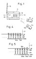
- the wireless transmission-reception control system includes more than one or, in general aspects of use, a plurality (while only two are shown in the drawing) of wireless transmitters 11 and lla which are preferably in a thin card type, and a wireless receiver 12 which receives data transmitted from the wireless transmitters 11 and lla.
- a call switch 13 or 13a functioning as a control switch is provided in top surface of the wireless transmitter 11 or lla, while the wireless receiver 12 generally comprises a body casing 14 and an antenna 15 mounted to the casing 14, while there are provided on the casing 14, as required, an operating slide switch 16, mode indicating lamp 17 and operation indicating lamp 18.
- a plurality of the wireless transmitters 11, 11a ... and the single wireless receiver 12 are combined to form the system in one unit, whereas, if desired, the system may be formed by combining a plurality of the wireless receivers 12 with the plurality of wireless transmitters 11, 11a ... into one unit.
- the wireless transmitters 11 and lla shall be detailed first.
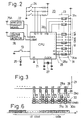
- a transmission control circuit 20 incorporated in each of the transmitters 11, 11a ..., and this circuit 20 includes a microcomputer formed by a one-chip CPU 21 to which the call switch 13 as well as a wireless transmitting means 22 including an antenna 15A and an ID code section 23 in which an ID code is fixedly set are connected.
- a set of transmission data defining, for example, a call sound of a tone pattern preliminarily set together with the ID code are provided from the CPU 21 to the wireless transmitting means 22 and are transmitted as a radio wave signal from the antenna 15A towards the wireless receiver 12.
- the tone pattern is set by means of a switch assembly 24, that is, a voltage applied to the CPU 21 is varied by making on and off switches of the assembly 24 so as to set the tone pattern to be transmitted as the transmission data.
- a switch assembly 24 that is, a voltage applied to the CPU 21 is varied by making on and off switches of the assembly 24 so as to set the tone pattern to be transmitted as the transmission data.
- an indicating lamp 25 to be lighted on upon operation of the call switch 13 is connected.
- a cell voltage drop detector 26 is connected to the CPU 21 to detect a lower voltage level of the cell than a set level, so that a detection signal of the thereby detected voltage drop will be transmitted out of the CPU 21 as included in the transmission data.
- a reference clock generator 27 is connected to the CPU 21 to detect a lower voltage level of the cell than a set level, so that a detection signal of the thereby detected voltage drop will be transmitted out of the CPU 21 as included in the transmission data.
- a specific ID code to each of the wireless transmitters 11 and 11a can be set and provided thereto.
- a comb-teeth shaped conducting pattern 30A is formed as connected initially to the respective lead wires 28, 28a ... 28n of the CPU 21, and then the connection of the pattern 30A at ground level is broken with respect to proper ones of the lead wires 28, 28a ... 28n by means of punch holes 31A, 31Aa ... 31An made by punching off connecting portions of the pattern to the lead wires, and the ID code is thereby set.
- the lead wires 28, 28a ... 28n are provided with conducting lands 29B, 29Ba ...
- a comb-teeth shaped conducting pattern 30B made at ground level is connected through jumpers 31B, 31Ba ... 31Bn, and then proper ones of the jumpers 31B, 31Ba ... 31Bn for setting the ID code are cut to break the connection.
- the transmission data are transmitted from the wireless transmitting means 22 of the wireless transmitter 11 as a radio wave signal, in such a signal format of one frame as shown in FIG. 6. That is, 20 bits of H0 to H19 are assigned for the ID code, a pre-receive TP is provided to the top, 3 bits of transmission data D0 to D2 are provided after the ID code, and a parity check P is provided to the last. With such 20 bits employed, it is made possible to set about 1,000,000 different ID codes, but the bit number for the ID code may be increased or decreased as occasion demands.
- the wireless receiver 12 shall be referred to in detail next.
- a reception circuit 40 which generally comprises a front end/decoder means 41 for decoding and taking out the transmission data received through the antenna 15, a mode switching means 42 for switching the setting of the receiver operation mode between a registering mode and a normal mode, and a system data table 43 for registering therein at least the ID code provided to the transmission data, and the ID code taken out of the front end/decoder means 41 is provided to a discriminating means 44 for collating the ID code with the already registered ID code in the system data table 43 and discriminating whether or not they are in coincidence.
- a manual change-over switch 47 is provided to the mode switching means 42 as shown in FIG. 8, so that the means 42 can be set either into the registering mode or into the normal mode by manually actuating the switch 47.
- the manual switch 47 is first depressed to actuate the mode switching means 42 to switch the mode over to the registering mode, the indicating lamp 17 is thereby lit, and the data registered in the system data table 43 are all cleared.
- a depression of the call switch 13 at one 11 of the plurality of wireless transmitters included in the system causes the transmission data in the transmitter 11 to be transmitted thereout as the radio wave signal, the transmitted data received through the antenna 15 by the wireless receiver 12 are decoded at the front end/decoder means 41, and the ID code is taken out of the data.
- the thus taken out ID code is registered as it is at the system data table 43, and, when the call switches of the remaining wireless transmitters are sequentially depressed to have their data transmitted to the receiver 12, the ID codes of the plurality of the wireless transmitters included in the system are sequentially registered in the wireless receiver 12.
- any ID code identical with already registered ID code is nullified upon being provided to the system data table 43, so as to prevent any double registering of the same ID code.
- the system data table 43 is preferably of a storing capacity enough for registering all of the ID codes determined by the bit number but, in practice, the capacity may be the one good enough for the ID codes only of the number of the wireless transmitter included in the system.
- the manual switch 47 is depressed again to actuate the mode switching means 42, and the mode is switched over to the normal mode.
- the call switch 13 of the wireless transmitter 11 in this state where the wireless receiver 12 is in the normal mode, the transmitted data received through the antenna 15 by the receiver 12 are decoded at the front end/decoder means 41, and the ID code is taken out of the data.
- the transmitted data of the particular ID code are provided to the transmission data discriminating means 45 to be decoded, and the control signal corresponding to the decoded data is provided as an output.
- the system is employed as such call chime system as shown in FIG.
- the control signal is conveyed to a phonic signal generating circuit 49 in a chime means 48 and to a timer 50 and a phonic sign is produced by a speaker 51 with its tone varied as occasion demands.
- the transmission data are formed by such 3 bits as DATA0 to DATA2, it is possible to prepare four different phonic call signs by actuating the phonic signal generating circuit 49 and speaker 51 with combinations of outputs at 1/0 ports PORT1 to PORT3 at the transmission data discriminating means 45.
- the discriminating means 45 provides at the PORT1 an output of "1" and the timer 50 is activated upon rising of this output, so that the phonic call sign can be generated by the speaker 51 depending on the set time of the timer 50.
- the bits of DATA1 and DATA2 are further discriminated to optimumly define the outputs at the PORT2 and PORT3 so that different phonic call signs as desired are to be produced, whereas, when DATA0 is "0", the PORT outputs are reset so as to wait for next output provision from the front end/decoder means 41.
- FIG. 10 For the phonic signal generating circuit 49, it may be possible to employ an arrangement, as shown in FIG. 10 as an example, which comprises a 3:4 decoder 52 formed by combining AND gates AND1 to AND3 and NOT gates NOT1 and NOT2 respectively arranged to receive the three port outputs PORT1 to PORT3 from the 1/0 ports of the discriminating means 45, and a melody IC 53 which receives four outputs from the decoder 52 to be thereby driven.
- FIG. 11 further, it may be also possible to add to the receiver, if required, means for transferring the sign to some other device associated by connecting a transistor 54 to the 1/0 port output terminal PORT1 of the discriminating means 45 so as to utilize the open output or, as in FIG. 12, by connecting a transistor 54A to the 1/0 port output terminal PORT1, further connecting a relay coil 54B to the collector of the transistor 54A, and disposing a relay contact 54C to oppose the relay coil 54B to be thereby opened and closed.
- the wireless receiver 12 should preferably be of such arrangement as shown in FIG. 13.
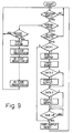
- the mode switching means in the basic arrangement of FIG. 7 comprises a start switch 55 and a timer control circuit 56, in which event the transmitted data from one of the wireless transmitters will cause the start switch 55 to be actuated, as in the time-chart of FIG. 15, then the timer control circuit 56 is started as triggered by the start switch 55, and the state of the registering mode is attained during a set time at this timer control circuit 56. Upon elapsing of this set time, the mode is automatically switched over to the normal mode (see also FIGS. 14 and 15).
- the operation indicating lamp 18 which is lighted on upon receipt at the wireless receiver 12 of the transmitted data may be provided in the timer control circuit 56.
- the wireless receiver 12 in the present aspect is to be operated in accordance with the flow-chart of FIG. 14, other arrangement and operation in the present instance are substantially the same as those in the receiver which has been disclosed with reference to FIG. 7 or 8 except for the automatic mode switching, and the same constituents as those in the receiver of FIG. 7 or 8 are denoted by the same reference numerals.
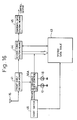
- the arrangement may be so made, if required, as to allow the already registered data maintained without being cleared and further data registered sequentially additionally. Further, the arrangement may be so made as to allow the registration to be reliably carried out even in an event where a delay is caused in the registering operation of the ID code, by replacing the timer control circuit 56 in the receiver of FIG. 13 with such a re-triggerable timer control circuit 56A as shown in FIG. 16, and extending the set time of the timer to have the registration carried out re-triggerably, as will be clear in view of FIG. 17 in comparison with FIG. 15.
- the wireless receiver allows a plurality of ID codes to be registered for each of preliminarily set groups of the codes.
- the system data table 43A is divided into a plurality of registering areas, and a group selecting switch 58 is connected to the table 43A so that one of the registering areas can be selected through this group selecting switch 58.
- a plurality of the operation indicating lamps 18a and 18b are connected to the mode switching means 42 for indicating the operation in respect of each of the divided registering areas so that any one of the registering areas in which the codes are being registered may be visualy confirmed, and the discriminating means 45 is provided with an output terminal means 59 having divided terminals Ol to On corresponding to the divided registering areas so as to obtain the control outputs in correspondence to the respective registering areas.
- a plurality of objects to be controlled may be controlled as divided into groups by means of the single wireless receiver, so that, in the case of forming, for example, a wireless security system, a plurality of objects can be monitored for each of divided groups of the objects, or, when a wireless chime system is formed, a plurality of the phonic call signs made mutually different for each of the divided object groups may be generated.
- the wireless receiver 12 of FIG. 18 is arranged for the mode switching by means of the manual switch in the same manner as in the receiver of FIG. 8, the arrangement can be modified as required into the automatic mode switching with such start switch and timer control circuit as in the case of FIG. 14 employed, or into such automatic mode switching arrangement as in the case of FIG. 16 where the re-triggerable operation is carried out by means of the re-triggerable timer control circuit.
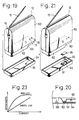
- a body casing 60 of the wireless receiver 12 comprises a bottom cover 61 securable to the casing 60 by means of screws not shown, at a stepped bottom part 62 of the casing 60, and such a movable member 63 of the start switch that renders the switch turned on in projected state under a spring load is provided to project out of lower surface of the bottom part 62.
- an operating hole 64 is provided through the cover for allowing the movable member 63 to be operated from the exterior by means of a proper jig passed through the hole 64 in a state where the bottom cover 61 is secured to the casing 60.
- the start switch can be turned on by placing the movable member 63 of the start switch into such projected state as shown by broken lines in FIG. 20 by means of the jig on users' side even when the bottom cover 61 is fixedly secured to the body casing 60 on manufacturers' side.
- This start switch actuatable without requiring the bottom cover 61 to be detached allows the receiver to be placed into sales in a state of incorporating a back-up cell for the system data table in the receiver on the side of the manufacturers, and required labor on the users' side can be simplified.
- the bottom cover is required to be detached.
- the prevention of such accidental turning on of the start switch can be reliably achieved by such arrangement as in FIG. 21, in which an "off" plate 65 is provided on inner surface of the bottom cover 61 as held by supports 66 enclosing the operating hole 64, so that the off plate 65 urges the movable member 63 into its retreated position, and the start switch can be reliably prevented from being put into "on” state even when an impact is given to the wireless receiver 12.
- the bottom cover 61 is to be detached to remove the "off” plate 65, and the movable member 63 may be placed into the projected "on” state.
- the arrangement should preferably be also so made that, after the mounting of the bottom cover 61, the start switch can be turned off by restoring the retreated state of the movable member 63 by the jig inserted through the hole 64.
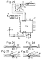
- a switch 75 is connected at its normally closed terminal NC to a minus side terminal of a back-up cell 70 and at normally opened terminal NO to a reset terminal RST of a CPU 67 forming a main element of the circuit, while a plus side terminal of the back-up cell 70 is connected to the anode of a diode 71 the cathode of which is connected to the cathode of another diode 72 connected at the anode to an external power source S, and a junction between the cathodes of the both diodes 71 and 72 is connected to a VDD terminal of the CPU 67.
- a resistor 73 is connected across the junction between the both diodes 71 and 72 and a junction between the normally opened terminal NO and the reset terminal RST, and a capacitor 74 is connected across the junction between the terminals NO and RST and the ground.
- the reset terminal RST of the CPU 67 will be at a voltage level of L, a reset signal is thus provided thereto and the receiver 12 is held in the reset state.
- a back-up power source voltage is caused to be applied to the VDD terminal even in a state where the external power source S is not connected.
- a series circuit of the resistor 73 and capacitor 74 acts to render the diode 71 to be in "off" state, and the voltage of the back-up power source 70 is not applied to the CPU.
- a lighting control arrangement for the mode indicating lamp 17 is formed by connecting the lamp 17 to a control mode output terminal M1 and a registration mode output terminal M2 of the CPU 67 through two series circuits of a diode and a resistor and mutually parallel.
- the resistor 76 in the series circuit connected to the output terminal M2 is set to be of a value smaller than the resistor 75 in the series circuit connected to the CPU output terminal M1, whereby, in a state where the wireless receiver 12 is switched into the registering mode, an "L" level pulse signal is provided out of the registering mode output terminal M2 to have the indicating lamp 17 lighted on.
- the indication of the particular registering mode can be made easier to be visually confirmed.
- the indicating lamp 17 therefore, it is preferable to employ a green color lamp, in view of that the green color light is larger in the brightness than, for example, red color light as seen in FIG. 23.
- the wireless transmitter 11 can be made thin.
- the transmitter 11 comprises a thin card-type hollow casing 80, which includes a plurality of key-top members 81 made depressible inward by cutting out the members in a cantilever type, a light permeating hole 82 made in the center of a front part adjacent front end side edge, inward projected locking arms 83 and 83a provided in rear part, and a seating part 84 made in the center of a rear end side edge for seating a later disclosed cell holder.
- a control circuit board 85 is provided for being accommodated within the casing 80, and this circuit board 85 carries a loop-shaped antenna 15A formed on front part of the board in a conductor pattern, a plurality of switches 24 at next stage portion of the front part for allowing the key-top members 81 of the casing 80 to be resiliently brought into contact with them, the CPU 21 in a rear part and next to the switches 24, a reference frequency generator 87 for a transmission circuit and also provided in the rear part and next to the switches 24, and a reference clock generator 27 comprising a quartz oscillator disposed in rear part of the board 85, while an indicating lamp 25 is provided in the center of the front part adjacent the front end side edge, and a conductor part 88 is provided along the rear end side for connection of the power source.
- the cell holder 90 to be fitted in the seating part 84 of the casing 80 is formed to have a cell supporter 92 for receiving a coin-shaped circular cell 91, and locking arms 93 and 93a at extended ends of the supporter 92 for lockingly engaging with the locking arms 83 and 83a of the casing 80 when the holder 90 is mounted to the casing 80, so that the cell holder 90 as well as the cell 91 will be held at a predetermined position.
- name-plate seals 95 and 96 on which article number, usage instructions and the like are printed are bonded, while the upper side seal 95 carries depression instructing prints 97 at positions opposing the key-top members 81 of the casing 80 and a light permeating part 98 formed in the center of front side end portion of the seal 95 to align with the lamp 25 of the circuit board 85 and the light permeating hole 82 of the casing 80.
- These control circuit board 85, casing 80 and seals 95 and 96 may preferably be joined integral by means of screws 99.
- the key-top member 81′ made thin at base portion for easy depression can be bent down to engage the switch 24′, but the depression made by the finger body portion is likely to cause depressing stroke of the key-top member 81′ to be relatively larger.
- the depression by the finger tip from the non-actuated state of FIG. 28 to actuated state of FIG. 29 of the key-top member 81 renders the depressing stroke to be relatively smaller.
- Such smaller depressing stroke of the key-top members 81 is contributive to a realization of the thin card-type wireless transmitters 11, in combination with such features that the planar loop-shaped antenna 15A is employed in the wireless transmitters, the ID code setting for the respective transmitters can be made preliminarily on the manufacturers' side to render any connecting member for connecting work on the users' side to be unnecessary, the key-top member is made thin at base portion to render the member elastically bendable and restorable without requiring any separate return spring, and so on. Further, the antenna 15A is disposed so as not to be covered by the user's hand upon depression of the key-top members 81, and the radio wave radiation efficiency of the antenna 15A is not to be reduced.
- FIG. 30 there is shown another arrangement suitable for applying the wireless transmitter 11 to a wireless chime system, in which the control circuit board 85 in the transmitter of FIG. 24 is made to include an insulating seal 100 having a plurality of apertures 101 and 101a and interposed between the conductor part 88 and the comb-teeth contactor 94.
- the conductor part 88 is so provided that, in the same manner as in the case of setting the mutually different ID codes in the foregoing embodiments, some of a plurality of branch conductors 102, 102a ...
- the insulating seal 100 is prepared to have the apertures 101 and 101a at different positions or in different size from other seals for all other transmitters, different ones only of the branch conductors 102, 102a ... 102n forming the conductor part 88 can be brought into contact with the minus electrode of the cell 91 through some of the teeth of the contactor 94 not covered by the insulating seal 100.
- the insulating seal 100A is provided with the apertures allowing first, third and sixth teeth of the contactor 94 to contact with the cell 91 so that a sound of such sequential tone of marimba will be produced.
- Another insulating seal 100B of FIG. 32 having apertures allowing first, second and sixth teeth of the contactor 94 to contact with the cell 91 produces an intermittent sound tone of the marimba, whereas still another insulating seal 100C of FIG. 33 having apertures which allow first and sixth teeth of the contactor 94 to contact with the cell 91 is to produce an ordinary buzzar sound.
- Other arrangements in the wireless transmitter shown in FIG. 30 are substantially the same as those in the transmitter shown in FIGS. 24 and 25, and the same constituents in the transmitter of FIG. 30 as those in FIGS. 24 and 25 are denoted by the same reference numerals.
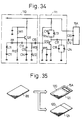
- the wireless transmitting means 22 comprises an oscillation circuit 110 and a frequency multiplier 111, to the latter of which the loop shaped antenna 15A is connected.
- the oscillation circuit 110 is formed to oscillate at a frequency determined by a crystal oscillator X11, coil L11 and capacitor C11, the oscillation of which is stabilized by means of a positive feedback amount determined by a capacitor C12 and a negative feedback amount determined by capacitors C13 and C14 and a coil L12.
- the oscillation circuit 110 includes a transistor Q11 for the crystalline oscillation, as DC biased by resistors R11 and R12 and with a negative feedback applied by a resistor R13.
- An output of the oscillation circuit 110 is applied through a capacitor C15 to a transistor Q12 biased by resistors R14 and R15 in the frequency multiplier 111, in which a higher harmonic of frequencies provided by a resonance circuit formed by a coil L13 and a capacitor C16 is selectively amplified to be provided through capacitors C17 and C19 to the loop antenna 15A and radiated thereout as a radio wave signal.
- the amplified higher harmonic is synchronized with a predetermined oscillation frequency by means of a parallel oscillation circuit of a capacitor C18 and a coil L14 so as to be of a low impedance with respect to other frequencies and to perform a filtration for removing any disturbing wave.
- the loop antenna 15A includes a capacitor C20 for improving the antenna radiation efficiency together with inductance component of the antenna 15A.
- a conducting shield 121 on the other surface of the substrate except for a portion corresponding to the loop antenna 15A, as will be seen in FIG. 35 showing the both surfaces of the substrate 86.
- the wireless transmission-reception control system can be utilized as such security system as shown in FIG. 36.
- the wireless transmitters 11 they may be any of various aspects of transmitting various security signals as the transmission data, and they may be formed in the form of such a transmitter 130 that generates the transmission data relative to fire alarming in association with a fire sensor, a transmitter 131 that provides monitoring data as the transmission data of opened/closed state detection signal or the like as to windows and doors in association with a crime prevention switches, or transmitters 132-134 that are to be carried by aged persons, patients and so on as hung on their neck for generating emergency signals.
- the transmission data from these transmitters are transmitted towards the wireless receiver 12 as driven by a driving member of the fire sensor, crime prevention switch or the like or by a manual depression of the call switch 13 of the transmitters.
- the interior arrangement of the wireless receiver 12 is as has been disclosed in the above, its front body face carries, for example, an area-code indicator 12a, a mode state indicator 12b, a security-information indicator 12c, control switches 12d, and a registering mode switch 12e.
- the transmission data from the security system are also the same in the basic structure as such format as in the case of the ID code referred to in the above with reference to FIG. 6, but they may be such that a pre-receive signal TP is provided at the top of each of the two frame data divided by, for example, a pause Tk, the frames are respectively formed by such security data S5-S0 disposed next to the ID code as alarming signal, dead-cell warning signal and crime preventing signal, function codes E1 and E0 disposed at next stage, and odd number parity check code P at the last stage.
- the system may be so arranged that the transmission data are transmitted continuously periodically as normal information and an abnormality is confirmed when the transmission of the normal information is interrupted.
- FIG. 38 these is shown a block circuit of a wireless receiver embodying the present invention when the same is applied to the foregoing security system, the basic arrangement of which is the same as that in the foregoing embodiments of FIGS. 7 and 8 and so on, and the same constituents are denoted by the same reference numerals.
- means 45B for decoding outputs of the ID code coincidence detecting means 44 into a zone unit code and the security data contained in output security signal of the zone unit code decoding means 45B is to be indicated at a security information indicating means 59A, while the output of the decoding means 45B is provided to an alarm operating means 59B to have such proper alarm means as a buzzar, siren or the like actuated.
- the security signal from the ID code coincidence discriminating means 45 includes a plurality of data
- means 45C for discriminating the type of the security data so that an output discrimination signal will be provided from the discriminating means 45C to the security information indicating means 59A.
- means 59C for scroll-indicating and controlling the watching zone code which denoting monitoring zone assigned to the respective wireless transmitters as well as the unit code, so that an output of the scroll indicating means 59C is provided to an address designating means 43B and an address designating signal is to be provided from this address designating means 43B to the system data table 43.
- the receiver 12 may also be designed to provide an output of the front end/decoder means 41 directly to an ID code indicating means 59D, to have the ID code displayed prior to the discrimination of its coincidence or non-coincidence.
- the zone unit scroll indicating means 59C is actuated and, as the security signal is provided from one of the wireless transmitters 11 while the zone and unit are indicated at the indicator 12a, the particular zone and unit codes being indicated at the moment are assigned to the ID code of the security signal received and are registered.
- the system data table 43 may be provided, as will be clear when FIG. 39 is also referred to, for registering 64 different ID codes with divisions of, for example, 8 zones and 8 units, together with other data.
- the wireless transmission-reception control system described herein can be employed as a transmission communication system utilizing telephone office line 140A as will be shown in FIG. 40, in which event a communication transmitting means 140 in which the wireless receiver 12 is included incorporates therein a communication control station 141 which transmits through the telephone line 140A the output of the receiver 12, while a communication receiving means 150 to which the information from the transmitting means 140 is provided comprises a communication control station 151 which receives the output from the communication control station 141 in the transmitting means 140, so that a communication can be achieved between the both communication control stations 141 and 151 respectively through telephone sets 142 and 155.
- the communication control stations 141 and 151 comprise respectively a MODEM and an NCU, by the latter of which the stations are connected and disconnected automatically with the telephone line 140A in a manner known per se.
- An output of the MODEM on the side of the communication receiving means 150 is provided through a controller 152 and a driving circuit 153 to an indicating means 154, so that the transmission data from the wireless transmitter 11 and decoded by the wireless receiver 12 on the side of the communication transmitting means 140 can be displayed on the indicator 154 at a further remote place than the receiver. It is made possible, therefore, to establish the data transmission beyond the transmission-reception zone between the wireless transmitters 11 and the wireless receiver 12. With the foregoing automatic mode switching arrangement employed here, it is made possible to automatically transmit the data to the indicator 154 installed at a remote position.
- the wireless transmission-reception control system described herein may also be employed for opening and closing operation of garage entrance shutters, as schematically shown in FIG. 41, in which event the chime means 48 in the embodiment of FIG. 8 is replaced by a shutter elevator 160 and the wireless transmitters 11, 11a ... are provided respectively with three operating switches 24 for elevating, lowering and stopping the shutter.
Landscapes
- Business, Economics & Management (AREA)
- Emergency Management (AREA)
- Physics & Mathematics (AREA)
- General Physics & Mathematics (AREA)
- Engineering & Computer Science (AREA)
- Computer Networks & Wireless Communication (AREA)
- Selective Calling Equipment (AREA)
- Alarm Systems (AREA)
- Mobile Radio Communication Systems (AREA)
- Transmitters (AREA)
Claims (5)
- Un système de commande pour un dispositif d'émission - réception sans fil comprenant:- un récepteur pour recevoir, à partir d'une pluralité d'émetteurs (11A, 11B) des signaux hertziens comportant des codes d'identification (codes ID) ainsi que des données, le récepteur comprenant des moyens de décodage (41) destinés à extraire le code d'identification et à décoder les données d'un signal reçu;- des moyens de discrimination (44) pour comparer un code d'identification reçu avec des codes d'identification stockés dans des moyens à registre de données (43) pour déterminer si le code d'identification est valable ou pas;- des moyens pour générer un signal de sortie en réponse aux composants de données de signaux reçus présentant des codes d'identification valables; etcaractérisé en ce que le récepteur comprend:- des moyens de commutation initiale (46) pour faire passer le récepteur en mode registre en réponse à la reception d'un signal originaire d'un desdits émetteurs; selon le mode registre, le récepteur réalisant l'extraction du code d'identification du signal reçu pour l'ajouter à ceux présents dans les moyens à registre de données;- des moyens de temporisation (56A) activés par les moyens de commutation initiale pour maintenir le récepteur dans ledit mode registre pendant une durée prédéterminée, et pour faire basculer automatiquement le récepteur vers un mode de décodage de données après l'écoulement de la durée prédéterminée, la durée prédéterminée étant remise à zéro quand un code d'identification est jugé valable par les moyens de discrimination.
- Un système selon la revendication 1, et comportant une pluralité d'émetteurs, un code d'identification unique étant associé à chaque émetteur.
- Un système selon la revendication 2, dans lequel chaque émetteur comprend un circuit intégré en forme de puce (21) ainsi qu'une pluralité de conducteurs (28) partant de ladite puce, le code d'identification pour l'émetteur étant préréglé en fixant pour chacune des conducteurs un niveau de signal.
- Un système selon la revendication 3, dans lequel chaque émetteur comprend un interrupteur d'appel (13, 13A), et dans lequel ledit récepteur est muni de moyens d'avertissement sonore (48, 49) pour générer un signal de sortie sonore en réponse à la réception de signaux dudit émetteur.
- Un système selon la revendication 4, dans lequel chaque émetteur comprend une antenne (15), une carte électronique de commande (85) à laquelle est reliée l'antenne, et sur laquelle est montée la puce; un boîtier relativement plat (80) renfermant la carte, la puce, et une pile d'alimentation plate (91) montée à l'intérieur du boîtier.
Applications Claiming Priority (2)
| Application Number | Priority Date | Filing Date | Title |
|---|---|---|---|
| JP1178688 | 1988-01-21 | ||
| JP11786/88 | 1988-01-21 |
Publications (3)
| Publication Number | Publication Date |
|---|---|
| EP0325433A2 EP0325433A2 (fr) | 1989-07-26 |
| EP0325433A3 EP0325433A3 (fr) | 1991-06-12 |
| EP0325433B1 true EP0325433B1 (fr) | 1996-09-11 |
Family
ID=11787616
Family Applications (1)
| Application Number | Title | Priority Date | Filing Date |
|---|---|---|---|
| EP89300457A Expired - Lifetime EP0325433B1 (fr) | 1988-01-21 | 1989-01-18 | Système de commande pour transmission-réception sans fil |
Country Status (3)
| Country | Link |
|---|---|
| EP (1) | EP0325433B1 (fr) |
| DE (1) | DE68927117T2 (fr) |
| HK (1) | HK1007616A1 (fr) |
Families Citing this family (1)
| Publication number | Priority date | Publication date | Assignee | Title |
|---|---|---|---|---|
| GB2292627A (en) * | 1994-08-23 | 1996-02-28 | Niagara Holdings Limited | Security systems |
Family Cites Families (3)
| Publication number | Priority date | Publication date | Assignee | Title |
|---|---|---|---|---|
| US4665397A (en) * | 1983-11-01 | 1987-05-12 | Universal Photonics, Inc. | Apparatus and method for a universal electronic locking system |
| DE3642951A1 (de) * | 1986-02-06 | 1987-08-20 | Notifier Co | Detektorsystem, insbesondere sicherungssystem, und verfahren zur erzeugung einer anzeige eines zustandes an mindestens einer entfernten stelle |
| US4855713A (en) * | 1988-10-07 | 1989-08-08 | Interactive Technologies, Inc. | Learn mode transmitter |
-
1989
- 1989-01-18 DE DE68927117T patent/DE68927117T2/de not_active Expired - Fee Related
- 1989-01-18 EP EP89300457A patent/EP0325433B1/fr not_active Expired - Lifetime
-
1998
- 1998-06-25 HK HK98106649A patent/HK1007616A1/en not_active IP Right Cessation
Also Published As
| Publication number | Publication date |
|---|---|
| DE68927117T2 (de) | 1997-04-03 |
| EP0325433A3 (fr) | 1991-06-12 |
| EP0325433A2 (fr) | 1989-07-26 |
| DE68927117D1 (de) | 1996-10-17 |
| HK1007616A1 (en) | 1999-04-16 |
Similar Documents
| Publication | Publication Date | Title |
|---|---|---|
| US5291193A (en) | Identification registration for a wireless transmission-reception control system | |
| US5386209A (en) | Cluster alarm monitoring system | |
| CA2200341C (fr) | Appareil de transmission optique de donnees et de localisation, et systeme, procede, emetteurs et recepteurs utilises conjointement | |
| US4728936A (en) | Control and display system | |
| US20060273895A1 (en) | Portable communication device alerting apparatus | |
| US20040124978A1 (en) | Transmitter for a wireless security and alerting system with at least one discreet button for identification | |
| EP0325433B1 (fr) | Système de commande pour transmission-réception sans fil | |
| JPH0315879B2 (fr) | ||
| CA2132663C (fr) | Clavier de saisie de donnees | |
| HK1007616B (en) | Wireless transmission-reception control system | |
| US6104319A (en) | Data entry keypad assembly | |
| EP0051325B1 (fr) | Système de commande à distance | |
| US6262653B1 (en) | Light flashing apparatus | |
| EP0727880A2 (fr) | Système de télécommande pour transmettre des signaux codés avec un émetteur auxiliaire qui apprend des codes des autres émetteurs | |
| JP3440648B2 (ja) | ワイヤレス通信制御システム | |
| JP2688949B2 (ja) | ワイヤレス送信制御システム | |
| JPH0554269A (ja) | 2重タンパー機能付ワイヤレス送信器 | |
| CA2281127C (fr) | Appareil d'eclairage clignotant | |
| US4764765A (en) | Binary display device to aid switch setting | |
| CN2329053Y (zh) | 集群式多信道报警器 | |
| JPH0638676B2 (ja) | ワイヤレス送信制御システム | |
| JPS581293A (ja) | 家庭用集中監視無線システム | |
| KR910005330Y1 (ko) | 무선 비상 경보장치 | |
| JPH021684A (ja) | ワイヤレス送信通報システム | |
| MY105608A (en) | Improvement in alarm control mechanisms |
Legal Events
| Date | Code | Title | Description |
|---|---|---|---|
| PUAI | Public reference made under article 153(3) epc to a published international application that has entered the european phase |
Free format text: ORIGINAL CODE: 0009012 |
|
| AK | Designated contracting states |
Kind code of ref document: A2 Designated state(s): DE GB |
|
| 17P | Request for examination filed |
Effective date: 19901210 |
|
| PUAL | Search report despatched |
Free format text: ORIGINAL CODE: 0009013 |
|
| AK | Designated contracting states |
Kind code of ref document: A3 Designated state(s): DE GB |
|
| 17Q | First examination report despatched |
Effective date: 19931105 |
|
| GRAG | Despatch of communication of intention to grant |
Free format text: ORIGINAL CODE: EPIDOS AGRA |
|
| GRAH | Despatch of communication of intention to grant a patent |
Free format text: ORIGINAL CODE: EPIDOS IGRA |
|
| GRAH | Despatch of communication of intention to grant a patent |
Free format text: ORIGINAL CODE: EPIDOS IGRA |
|
| GRAA | (expected) grant |
Free format text: ORIGINAL CODE: 0009210 |
|
| AK | Designated contracting states |
Kind code of ref document: B1 Designated state(s): DE GB |
|
| REF | Corresponds to: |
Ref document number: 68927117 Country of ref document: DE Date of ref document: 19961017 |
|
| PLBE | No opposition filed within time limit |
Free format text: ORIGINAL CODE: 0009261 |
|
| STAA | Information on the status of an ep patent application or granted ep patent |
Free format text: STATUS: NO OPPOSITION FILED WITHIN TIME LIMIT |
|
| 26N | No opposition filed | ||
| PGFP | Annual fee paid to national office [announced via postgrant information from national office to epo] |
Ref country code: GB Payment date: 19980109 Year of fee payment: 10 |
|
| PGFP | Annual fee paid to national office [announced via postgrant information from national office to epo] |
Ref country code: DE Payment date: 19980123 Year of fee payment: 10 |
|
| PG25 | Lapsed in a contracting state [announced via postgrant information from national office to epo] |
Ref country code: GB Free format text: LAPSE BECAUSE OF NON-PAYMENT OF DUE FEES Effective date: 19990118 |
|
| GBPC | Gb: european patent ceased through non-payment of renewal fee |
Effective date: 19990118 |
|
| PG25 | Lapsed in a contracting state [announced via postgrant information from national office to epo] |
Ref country code: DE Free format text: LAPSE BECAUSE OF NON-PAYMENT OF DUE FEES Effective date: 19991103 |