EP0325499A1 - Erfassungsgerät zur Digitalisierung von Hochdynamiksignalen - Google Patents
Erfassungsgerät zur Digitalisierung von Hochdynamiksignalen Download PDFInfo
- Publication number
- EP0325499A1 EP0325499A1 EP89400029A EP89400029A EP0325499A1 EP 0325499 A1 EP0325499 A1 EP 0325499A1 EP 89400029 A EP89400029 A EP 89400029A EP 89400029 A EP89400029 A EP 89400029A EP 0325499 A1 EP0325499 A1 EP 0325499A1
- Authority
- EP
- European Patent Office
- Prior art keywords
- voltage
- signals
- acquisition device
- digital
- samples
- Prior art date
- Legal status (The legal status is an assumption and is not a legal conclusion. Google has not performed a legal analysis and makes no representation as to the accuracy of the status listed.)
- Granted
Links
Images
Classifications
-
- H—ELECTRICITY
- H03—ELECTRONIC CIRCUITRY
- H03M—CODING; DECODING; CODE CONVERSION IN GENERAL
- H03M1/00—Analogue/digital conversion; Digital/analogue conversion
- H03M1/12—Analogue/digital converters
- H03M1/18—Automatic control for modifying the range of signals the converter can handle, e.g. gain ranging
- H03M1/186—Automatic control for modifying the range of signals the converter can handle, e.g. gain ranging in feedforward mode, i.e. by determining the range to be selected directly from the input signal
- H03M1/187—Automatic control for modifying the range of signals the converter can handle, e.g. gain ranging in feedforward mode, i.e. by determining the range to be selected directly from the input signal using an auxiliary analogue/digital converter
Definitions
- the subject of the present invention is an acquisition device making it possible to digitize signals with high dynamics after possible amplification.
- Seismic prospecting methods generally include the emission of waves by a seismic source, the reception of waves returned by the various reflecting interfaces of the subsoil and the production of seismic recordings representative of the configuration of the subsoil.
- the reception of the waves is carried out by reception devices comprising a very large number of sensors distributed along the seismic profile to be studied.
- the sensors are distributed all along and inside a flexible, tight sheath, of great length which is called seismic flute.
- the set of sensors is generally divided into a plurality of sub-assemblies.
- the signals picked up by the sensors of the same sub-assembly are most often collected by an electronic data acquisition device which digitizes and records them.
- the signals recorded by the various acquisition devices are transmitted sequentially to a central control and recording laboratory by means of a multiplexed transmission system by means of transmission lines or by radio.
- a transmission system is described, for example, in French patent No. 2,471,088.
- seismic reception devices comprising an increased number of seismic sensors and consequently to increase in parallel the number and the complexity of the acquisition devices used to collect all the signals received. It is therefore desirable to use acquisition devices whose various electronic modules are optimized to reconcile performance, reliability and relatively low electrical consumption.
- the acquisition devices used in particular in seismic transceiver systems for example include an analog multiplexer whose different inputs are connected to the various signal sensors, either directly or via fixed gain preamplifiers and filters.
- the output of the multiplexer is connected to a single amplifier made up of several stages connected in series or in parallel. Each of the stages can be associated with a feedback network.
- a selection member chooses the number of amplification stages and / or their respective gains, so as to give each amplified signal a suitable amplitude before applying it to an analog-digital converter. This transforms each signal sample into a digital word, by comparing its amplitude with a fixed reference signal applied to it.
- the acquisition device makes it possible to transform an analog signal into samples of digitized signals with a relatively simple structure where the applied signals are practically not altered during the whole phase of their acquisition.
- sampling means and an analog-digital converter adapted to transform the signal samples delivered successively by the sampling means, into digital words, in relation to a reference voltage, and selection means for generating a voltage. reference for said converter which depends on the amplitude of the signals to be digitized.
- the selection means comprise a generator producing a stabilized DC voltage of fixed amplitude, a voltage divider means producing a plurality of fixed secondary voltages and selection means comprising several voltage comparators for comparing the amplitude of each of the successive samples with said secondary voltages derived from the stabilized voltage, a switching means for choosing one of the secondary voltages and a logic assembly for generating a control signal of the switching means for choosing from among the secondary voltages, that which suitable for digitizing each of the samples of successive signals to be digitized, and a signal indicative of the selected secondary voltage.
- the stabilized voltage divider means comprises for example a network of resistors whose values are chosen so that the secondary voltages are in a proportional relationship determined with respect to each other.
- the signals to be digitized, previously amplified if necessary in a fixed gain amplifier are directly applied to the sampling and analog-digital conversion means.
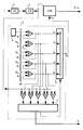
- FIG. 1 shows a block diagram of the device .
- the devices to be digitized are applied to a fixed gain amplifier 1 if their level is insufficient.
- the amplified signals are directed to the input of a blocker sampler 2.
- the output of this one is connected to the input of an analog-digital converter 3.
- the device comprises a set 4 for generating a reference voltage variable.
- This assembly 4 includes a stabilized voltage source 5 delivering a very constant voltage V S.
- a voltage divider network comprising for example five resistors R1 to R5 interconnected in series, connects the output of the voltage source 5 to earth.
- the values of the various resistors R1 to R5 of the network are chosen so that the voltages measurable at the nodes interconnection of resistors R1 and R2, R2 and R3, R3 and R4, R4 and R5, are respectively equal to V S / 2, V S / 4, V S / 8 and V S / 16 for example.
- the output of source 5 and the various interconnection nodes are respectively connected to the inputs of five buffer amplifier A1, A2 ... A5.
- the outputs of these buffer amplifiers are connected to five inputs X1, X2 ... X5 of a multiplexer 6.
- the output of the latter is connected to the input e ref of the analog-digital converter 3 adapted to receive the voltage benchmark depending on which the conversion to digital signals is performed.
- the outputs of the buffer amplifiers A1 to A5 are respectively also connected to a first input of five voltage comparators C1, C2 ... C5. The second input of each of these is connected to the output of the sampler-blocker 2.
- comparators C1 to C5 are connected to inputs of a set of logic gates 7 adapted to select the voltage V R to be applied to the input e ref of the converter 3 from the voltages available at the inputs X1 to X5 of the multiplexer 6 , and to deliver a signal indicative of the value G of the gain to be associated with each digital word N (Ve) coming from the analog-digital converter 3.
- the selection operations can be summarized by the table below where the first column P corresponds to the different ranges of variation of the voltage V e , delimited by the voltages V S , V S / 2, V S / 4, V S / 8 and V S / 16; the second column X, at the number of an input X1 to X5 of the multiplexer 6 actually connected to the input e ref of the analog-digital converter 3 as a function of the range where the input voltage V e is located and the third column , the 3-bit digital word G associated with each digital value N (Ve) as a function of the switching carried out by the multiplexer 6.
- Each digitized signal sample is therefore defined by two digital words, one N (Ve) corresponding to a mantissa and the other G to an associated exponent.
- the digital-analog converter 3 and the various circuits for selecting the reference voltage therefore make it possible to digitize signals with very wide dynamics.
Landscapes
- Engineering & Computer Science (AREA)
- Theoretical Computer Science (AREA)
- Analogue/Digital Conversion (AREA)
- Arrangements For Transmission Of Measured Signals (AREA)
- Geophysics And Detection Of Objects (AREA)
Applications Claiming Priority (2)
| Application Number | Priority Date | Filing Date | Title |
|---|---|---|---|
| FR8800764A FR2626423A1 (fr) | 1988-01-21 | 1988-01-21 | Dispositif d'acquisition pour la numerisation de signaux a grande dynamique |
| FR8800764 | 1988-01-21 |
Publications (2)
| Publication Number | Publication Date |
|---|---|
| EP0325499A1 true EP0325499A1 (de) | 1989-07-26 |
| EP0325499B1 EP0325499B1 (de) | 1994-04-20 |
Family
ID=9362573
Family Applications (1)
| Application Number | Title | Priority Date | Filing Date |
|---|---|---|---|
| EP89400029A Expired - Lifetime EP0325499B1 (de) | 1988-01-21 | 1989-01-05 | Erfassungsgerät zur Digitalisierung von Hochdynamiksignalen |
Country Status (8)
| Country | Link |
|---|---|
| US (1) | US4990913A (de) |
| EP (1) | EP0325499B1 (de) |
| JP (1) | JPH02207618A (de) |
| CN (1) | CN1013538B (de) |
| CA (1) | CA1296805C (de) |
| DE (1) | DE68914691T2 (de) |
| FR (1) | FR2626423A1 (de) |
| NO (1) | NO890238L (de) |
Cited By (1)
| Publication number | Priority date | Publication date | Assignee | Title |
|---|---|---|---|---|
| GB2245443A (en) * | 1990-06-22 | 1992-01-02 | Philips Electronic Associated | Signal digitiser |
Families Citing this family (22)
| Publication number | Priority date | Publication date | Assignee | Title |
|---|---|---|---|---|
| US5343200A (en) * | 1990-08-31 | 1994-08-30 | Canon Kabushiki Kaisha | Analog/digital converter with digital automatic gain control |
| FR2691026B1 (fr) * | 1992-05-07 | 1997-01-03 | Thomson Csf | Convertisseur analogique-numerique et boucle d'asservissement utilisant un tel convertisseur. |
| US5359327A (en) * | 1993-05-28 | 1994-10-25 | Brown Eric W | A/D converter system with interface and passive voltage reference source |
| US5488368A (en) * | 1993-05-28 | 1996-01-30 | Technoview Inc. | A/D converter system and method with temperature compensation |
| US5610604A (en) * | 1994-12-07 | 1997-03-11 | Panasonic Technologies, Inc. | Analog to digital converter providing varying digital resolution |
| US5684480A (en) * | 1995-01-30 | 1997-11-04 | Telefonaktiebolaget Lm Ericsson | Wide dynamic range analog to digital conversion |
| US5659313A (en) * | 1995-03-31 | 1997-08-19 | Panasonic Technologies, Inc. | System and method for reducing noise during analog to digital conversion |
| US5874736A (en) * | 1996-10-25 | 1999-02-23 | Exergen Corporation | Axillary infrared thermometer and method of use |
| US6298459B1 (en) * | 1997-07-18 | 2001-10-02 | Fujitsu Limited | Analog to digital converter with encoder circuit and testing method therefor |
| US6703951B2 (en) | 1997-07-18 | 2004-03-09 | Fujitsu Limited | Analog to digital converter with encoder circuit and testing method therefor |
| US6317070B1 (en) * | 1998-08-20 | 2001-11-13 | Telefonaktiebolaget Lm Ericsson (Publ) | Floating-point analog-to-digital converter |
| US6255974B1 (en) | 1999-01-08 | 2001-07-03 | Mitsubishi Electric And Electronics Usa, Inc | Programmable dynamic range sigma delta A/D converter |
| DE19936327C2 (de) * | 1999-08-02 | 2003-04-24 | Infineon Technologies Ag | Verfahren und Vorrichtung zur Durchführung von ratiometrischen Messungen unter Verwendung eines Analog/Digital- oder eines Digital/Analog-Umsetzers, Analog/Digital- oder Digital/Analog-Umsetzer, und Verfahren zum Betreiben eines Analog/Digital- oder Digital/Analog-Umsetzers |
| US7062168B1 (en) * | 2001-03-19 | 2006-06-13 | Dbm Optics, Incorporated | Bifurcated range stages to increase speed or dynamic range of measuring instruments and associated methods |
| US20040134988A1 (en) * | 2003-01-09 | 2004-07-15 | Hand Held Products, Inc. | Analog-to-digital converter with automatic range and sensitivity adjustment |
| JP2005094678A (ja) * | 2003-09-19 | 2005-04-07 | Sanyo Electric Co Ltd | ビデオ信号処理装置及びテレビジョン受像装置 |
| US20100164768A1 (en) * | 2008-12-31 | 2010-07-01 | Texas Instruments Incorporated | Providing digital codes representing analog samples with enhanced accuracy while using an adc of lower resolution |
| WO2014200473A1 (en) | 2013-06-12 | 2014-12-18 | Schneider Electric It Corporation | Dynamic sensitivity adjustment for adc measurements |
| CN103837887B (zh) * | 2014-02-19 | 2016-07-20 | 中国地震局地球物理研究所 | 一种高动态范围地震信号分级采集方法及系统 |
| TWI643451B (zh) * | 2017-10-02 | 2018-12-01 | 緯創資通股份有限公司 | 具多階轉換範圍的類比數位轉換器、放大電路及相關類比數位轉換方法 |
| CN112865797A (zh) * | 2021-03-01 | 2021-05-28 | 云南电网有限责任公司电力科学研究院 | 一种基于adc的高精度采样系统 |
| CN113110671B (zh) * | 2021-04-16 | 2022-08-23 | 浙江正泰中自控制工程有限公司 | 一种用于控制系统的可变功耗模拟量电流输出电路 |
Citations (5)
| Publication number | Priority date | Publication date | Assignee | Title |
|---|---|---|---|---|
| FR1481960A (fr) * | 1966-01-10 | 1967-05-26 | Societe D'etudes, Recherches Et Constructions Electroniques | Procédé et dispositif de codage numérique |
| US3411153A (en) * | 1964-10-12 | 1968-11-12 | Philco Ford Corp | Plural-signal analog-to-digital conversion system |
| US3585631A (en) * | 1969-11-26 | 1971-06-15 | Westinghouse Electric Corp | Square law analog-to-digital converter |
| US3699325A (en) * | 1969-10-09 | 1972-10-17 | Shell Oil Co | Time-shared instantaneous gain-ranging amplifier |
| FR2580877A1 (fr) * | 1985-04-19 | 1986-10-24 | Labo Electronique Physique | Convertisseur analogique-numerique non lineaire |
Family Cites Families (13)
| Publication number | Priority date | Publication date | Assignee | Title |
|---|---|---|---|---|
| US3603972A (en) * | 1968-12-24 | 1971-09-07 | Texaco Inc | Amplifier system |
| US3597761A (en) * | 1969-11-14 | 1971-08-03 | American Astronics Inc | High-speed analog-to-digital converter and method therefor |
| BE793746A (fr) * | 1972-01-11 | 1973-07-09 | Sercel Rech Const Elect | Amplificateur d'echantillons de signaux analogiques avec reglage de gain automatique |
| IE38230B1 (en) * | 1972-09-15 | 1978-01-18 | Ind Des Telecommunications Com | Improvements in digital coders |
| US3813609A (en) * | 1972-11-27 | 1974-05-28 | Petty Ray Geophysical Inc | Multiple stage sample normalizing amplifier with automatic gain prediction |
| US3919657A (en) * | 1973-11-12 | 1975-11-11 | Texaco Inc | Wide dynamic range amplifier system with slew rate control |
| FR2441956A1 (fr) * | 1978-11-17 | 1980-06-13 | Inst Francais Du Petrole | Methode d'amplification de signaux multiplexes et dispositif de mise en oeuvre |
| JPS55100741A (en) * | 1979-01-26 | 1980-07-31 | Hitachi Ltd | Multi-input comparator |
| US4393368A (en) * | 1980-05-16 | 1983-07-12 | Motorola Inc. | Multithreshold A/D converter utilizing error amplifiers |
| JPS57152726A (en) * | 1981-03-17 | 1982-09-21 | Toshiba Corp | A/d converting circuit |
| US4684924A (en) * | 1982-09-30 | 1987-08-04 | Wood Lawson A | Analog/digital converter using remainder signals |
| US4584560A (en) * | 1984-06-11 | 1986-04-22 | Geometrics, Inc. | Floating point digitizer |
| JPS61142823A (ja) * | 1984-12-17 | 1986-06-30 | Tokyo Keiki Co Ltd | 信号変換方式 |
-
1988
- 1988-01-21 FR FR8800764A patent/FR2626423A1/fr active Granted
-
1989
- 1989-01-05 EP EP89400029A patent/EP0325499B1/de not_active Expired - Lifetime
- 1989-01-05 DE DE68914691T patent/DE68914691T2/de not_active Expired - Fee Related
- 1989-01-13 CN CN89100281.2A patent/CN1013538B/zh not_active Expired
- 1989-01-19 NO NO89890238A patent/NO890238L/no unknown
- 1989-01-20 JP JP1011758A patent/JPH02207618A/ja active Pending
- 1989-01-20 CA CA000588728A patent/CA1296805C/fr not_active Expired - Lifetime
- 1989-01-23 US US07/299,313 patent/US4990913A/en not_active Expired - Fee Related
Patent Citations (5)
| Publication number | Priority date | Publication date | Assignee | Title |
|---|---|---|---|---|
| US3411153A (en) * | 1964-10-12 | 1968-11-12 | Philco Ford Corp | Plural-signal analog-to-digital conversion system |
| FR1481960A (fr) * | 1966-01-10 | 1967-05-26 | Societe D'etudes, Recherches Et Constructions Electroniques | Procédé et dispositif de codage numérique |
| US3699325A (en) * | 1969-10-09 | 1972-10-17 | Shell Oil Co | Time-shared instantaneous gain-ranging amplifier |
| US3585631A (en) * | 1969-11-26 | 1971-06-15 | Westinghouse Electric Corp | Square law analog-to-digital converter |
| FR2580877A1 (fr) * | 1985-04-19 | 1986-10-24 | Labo Electronique Physique | Convertisseur analogique-numerique non lineaire |
Non-Patent Citations (1)
| Title |
|---|
| PATENT ABSTRACTS OF JAPAN, vol. 6, no. 254 (E-148)[1132], 14 décembre 1982, page 54 E 148; & JP-A-57 152 726 (TOKYO SHIBAURA DENKI K.K.) 21-09-1982 * |
Cited By (2)
| Publication number | Priority date | Publication date | Assignee | Title |
|---|---|---|---|---|
| GB2245443A (en) * | 1990-06-22 | 1992-01-02 | Philips Electronic Associated | Signal digitiser |
| GB2245443B (en) * | 1990-06-22 | 1994-05-25 | Philips Electronic Associated | Signal digitiser |
Also Published As
| Publication number | Publication date |
|---|---|
| EP0325499B1 (de) | 1994-04-20 |
| NO890238D0 (no) | 1989-01-19 |
| CN1013538B (zh) | 1991-08-14 |
| FR2626423A1 (fr) | 1989-07-28 |
| CA1296805C (fr) | 1992-03-03 |
| JPH02207618A (ja) | 1990-08-17 |
| US4990913A (en) | 1991-02-05 |
| DE68914691D1 (de) | 1994-05-26 |
| CN1039689A (zh) | 1990-02-14 |
| DE68914691T2 (de) | 1994-08-04 |
| FR2626423B1 (de) | 1995-05-24 |
| NO890238L (no) | 1989-07-24 |
Similar Documents
| Publication | Publication Date | Title |
|---|---|---|
| EP0325499B1 (de) | Erfassungsgerät zur Digitalisierung von Hochdynamiksignalen | |
| EP0057802B1 (de) | Phasen- und Amplitudenmessung für ein Bohrlochsystem zur Bestimmung der dielektrischen Eigenschaften | |
| EP1080433B1 (de) | Schaltung und verfahren zum kalibrieren der phasenabweichung zwischen mehreren analog-digital-wandlern in einem datenerfassungssystem | |
| EP0762145B1 (de) | Pulsverarbeitungssystem für einen Gammateilchen-CdTe-Strahlungsdetektor | |
| EP3566308A1 (de) | Steuerungsschaltungen für ultraschallwandler | |
| CA2020100A1 (fr) | Dispositif perfectionne pour effectuer des essais sous contraintes sur des echantillons de roche et autres materiaux | |
| EP0406080B1 (de) | Verfahren und Gerät zur Erfassung und genauen Digitalisierung analoger Daten | |
| WO1993025919A1 (fr) | Systeme d'acquisition sismique pourvu de moyens de traitement decentralises | |
| FR2787201A1 (fr) | Methode et dispositif d'acquisition synchronisee de signaux sismiques | |
| EP3438692B1 (de) | Abtast- und halteschaltung für ein lidar-system | |
| FR2623351A1 (fr) | Circuit de modulation de phase, repeteur le comportant, et ensemble de telecommunications comportant des repeteurs | |
| FR2707115A1 (fr) | Procédé pour produire des formes d'ondelettes sismiques ayant une énergie de lobes latéraux minimale. | |
| CA1323656C (fr) | Procede de mesure de la frequence d'un signal periodique et frequencemetre pour la mise en oeuvre du procede du procede | |
| FR2975187A1 (fr) | Mesure differentielle de tension | |
| FR2459531A1 (fr) | Circuit generateur de fonctions temporelles optimales | |
| EP0201415B1 (de) | Logarithmische Wandler und ihre Anwendung zur übertragenen Lichtmessung | |
| CA1263188A (fr) | Dispositif pour amplifier et echantillonner des signaux a grande dynamique | |
| EP0463964B2 (de) | Anlage zur Erzeugung und zum Empfang von Ultraschall | |
| WO1988004124A1 (fr) | Dispositif de traitement d'un signal electrique audiofrequence | |
| Asch | Seismic recording systems | |
| EP0204599A1 (de) | Verfahren und Vorrichtung zur Bestimmung des Kennzeichens von grosser Distanz einer seismischen Sendergruppe | |
| FR2565695A1 (fr) | Procede et dispositif de mesure de la composante reactive d'une impedance complexe | |
| Havskov et al. | Analog to digital converter | |
| FR2469720A1 (fr) | Systeme ameliorant les procedes de mesures acoustiques | |
| FR2697388A1 (fr) | Procédé et dispositif de conversion dynamique analogique/numérique et numérique/analogique. |
Legal Events
| Date | Code | Title | Description |
|---|---|---|---|
| PUAI | Public reference made under article 153(3) epc to a published international application that has entered the european phase |
Free format text: ORIGINAL CODE: 0009012 |
|
| 17P | Request for examination filed |
Effective date: 19890112 |
|
| AK | Designated contracting states |
Kind code of ref document: A1 Designated state(s): DE GB IT NL |
|
| 17Q | First examination report despatched |
Effective date: 19920925 |
|
| ITF | It: translation for a ep patent filed | ||
| GRAA | (expected) grant |
Free format text: ORIGINAL CODE: 0009210 |
|
| AK | Designated contracting states |
Kind code of ref document: B1 Designated state(s): DE GB IT NL |
|
| REF | Corresponds to: |
Ref document number: 68914691 Country of ref document: DE Date of ref document: 19940526 |
|
| GBT | Gb: translation of ep patent filed (gb section 77(6)(a)/1977) |
Effective date: 19940504 |
|
| PLBE | No opposition filed within time limit |
Free format text: ORIGINAL CODE: 0009261 |
|
| STAA | Information on the status of an ep patent application or granted ep patent |
Free format text: STATUS: NO OPPOSITION FILED WITHIN TIME LIMIT |
|
| 26N | No opposition filed | ||
| PGFP | Annual fee paid to national office [announced via postgrant information from national office to epo] |
Ref country code: GB Payment date: 19951222 Year of fee payment: 8 |
|
| PGFP | Annual fee paid to national office [announced via postgrant information from national office to epo] |
Ref country code: NL Payment date: 19960131 Year of fee payment: 8 |
|
| PGFP | Annual fee paid to national office [announced via postgrant information from national office to epo] |
Ref country code: DE Payment date: 19960215 Year of fee payment: 8 |
|
| PG25 | Lapsed in a contracting state [announced via postgrant information from national office to epo] |
Ref country code: GB Effective date: 19970105 |
|
| PG25 | Lapsed in a contracting state [announced via postgrant information from national office to epo] |
Ref country code: NL Effective date: 19970801 |
|
| GBPC | Gb: european patent ceased through non-payment of renewal fee |
Effective date: 19970105 |
|
| NLV4 | Nl: lapsed or anulled due to non-payment of the annual fee |
Effective date: 19970801 |
|
| PG25 | Lapsed in a contracting state [announced via postgrant information from national office to epo] |
Ref country code: DE Effective date: 19971001 |
|
| PG25 | Lapsed in a contracting state [announced via postgrant information from national office to epo] |
Ref country code: IT Free format text: LAPSE BECAUSE OF NON-PAYMENT OF DUE FEES;WARNING: LAPSES OF ITALIAN PATENTS WITH EFFECTIVE DATE BEFORE 2007 MAY HAVE OCCURRED AT ANY TIME BEFORE 2007. THE CORRECT EFFECTIVE DATE MAY BE DIFFERENT FROM THE ONE RECORDED. Effective date: 20050105 |