EP0325565A1 - Sensoreinrichtung - Google Patents
Sensoreinrichtung Download PDFInfo
- Publication number
- EP0325565A1 EP0325565A1 EP89830008A EP89830008A EP0325565A1 EP 0325565 A1 EP0325565 A1 EP 0325565A1 EP 89830008 A EP89830008 A EP 89830008A EP 89830008 A EP89830008 A EP 89830008A EP 0325565 A1 EP0325565 A1 EP 0325565A1
- Authority
- EP
- European Patent Office
- Prior art keywords
- coded
- revolving
- metric
- elements
- drum
- Prior art date
- Legal status (The legal status is an assumption and is not a legal conclusion. Google has not performed a legal analysis and makes no representation as to the accuracy of the status listed.)
- Granted
Links
Images


Classifications
-
- G—PHYSICS
- G06—COMPUTING OR CALCULATING; COUNTING
- G06M—COUNTING MECHANISMS; COUNTING OF OBJECTS NOT OTHERWISE PROVIDED FOR
- G06M1/00—Design features of general application
- G06M1/27—Design features of general application for representing the result of count in the form of electric signals, e.g. by sensing markings on the counter drum
- G06M1/272—Design features of general application for representing the result of count in the form of electric signals, e.g. by sensing markings on the counter drum using photoelectric means
-
- G—PHYSICS
- G06—COMPUTING OR CALCULATING; COUNTING
- G06M—COUNTING MECHANISMS; COUNTING OF OBJECTS NOT OTHERWISE PROVIDED FOR
- G06M1/00—Design features of general application
- G06M1/27—Design features of general application for representing the result of count in the form of electric signals, e.g. by sensing markings on the counter drum
- G06M1/274—Design features of general application for representing the result of count in the form of electric signals, e.g. by sensing markings on the counter drum using magnetic means; using Hall-effect devices
Definitions
- the object of the present invention is a transducer measuring device based on the positioning of at least one pair of revolving mechanical elements. This device can be applied with advantage in the field of measuring angle dimensions, angular displacements, the number of revolutions and the indications of a mechanical meter for measuring fluids, gases or electricity.
- a known type of meter for example, is composed of an assembly of interacting revolving elements, controlled by a driving gear whose movement is related to the flow of fluid or gas passing in a given pipeline, in such a way as to obtain a correlation between the quantity of fluid or gas which has passed through and the number of revolutions or fractions of a revolution made by the revolving meter elements.
- Each revolving element is subdivided into a predetermined number of zones, each bearing a number.
- the revolving elements are coupled in such a way that as soon as one finishes a revolution it causes the one lying next to it to rotate at a predetermined angle.
- the indication of the number of revolutions or fraction of a revolution made by the assembly can be displayed and/or the mechanical measurement can be transduced into an electric signal which can be suitably handled.
- a transducer device capable, for example, of allowing the number of revolutions shown by a meter of the above-mentioned type to be transduced, in which decade wheels are provided together with the metric drums, that is wheels comprising openings positioned according to a predetermined code, the indication of whose position is appropriately taken, the device being able also to comprise an element acting as a vernier, whose reading is taken and processed with the reading of said decade wheels so as to increase measurement precision.
- the transducer devices of the type described above produced up to the present day, foresee three wheel assemblies keyed to different axes.
- the first assembly is entirely mechanical and serves to provide rotary motion for the second assembly, which is composed of metric drums, on the first of which a sensor "vernier" can be mounted, said drums transmitting the motion to the third assembly, composed of elements coded according to a decadal code.
- Transducer devices are also known which foresee wheel units keyed to the same shaft.
- a device for indicating the distance covered by a vehicle comprising a mechanical meter, composed of wheels each comprising a contact drum and a numbered disk.
- the contact drums are provided with protruding contact elements which are read by sliding contacts. Readings can also be effected by the eye from the numbered disk.
- US-A-3.723.711 describes another reading device comprising at least one numbered wheel, provided on its periphery of protruding elements, which are read by mobile contacts.
- a reading device comprising at least one numbered rotating drum, which bears a series of numbers or symbols on its periphery.
- the flat part of the drum is divided into as many sectors as the numbers or symbols contemplated; each sector bears notches, which are different for each sector.
- the various sectors are lighted and the light passing through the notches is received by a photo-electric cell from which the number or symbol indicated derives.
- this invention overcomes the drawbacks relating to the realizations described above, it has the defect of leading to errors in reading when the number of numbered rotating drums (and therefore the numbers to be read) is more than one.
- synchronized angular displacement is not obtained at the passage from the lower to the upper decade, in the case of the drums being numberd from 0 to 9, or, in any case, at the passage from the reading made up of a determined symbol "n" on the preceding drum and of the last symbol on the following drum, to the reading made up of the symbol "n+1" on the preceding drum and of the first symbol on the following drum.
- the aim of the present invention is, therefore, to simplify the construction of a transducer device of the type mentioned and thereby lower its production costs.
- a further aim is to allow remote reading of the transducer without the use of sliding contacts.
- a third aim is to prevent the occurrence of reading errors at the passage from one decade to the other.
- the above aim has been achieved by keying the metric drums and the coded revolving elements, which make up the revolving metric indicators, to the same shaft.
- the number of axes has been brought from three to two, a reduction with respect to the devices of the known type.
- the reduction of the number of the axes reduces friction in the system; this is very advantageous as metric meters are being dealt with where passive absorption of power by the measuring member is very important, as in the case of electric meter, for example.
- the coded revolving elements are, in addition, each positioned ahead out of phase at an appropriate angle with respect to the preceding coded revolving element, or positioned further to the right; in addition the device for the electronic processing of the signal read on the coded revolving elements, does not allow a signal, having a value lower than that of any signal previously sent, to be issued to the displaying device. In this way, errors which can occur at the passage from one decade to the other are eliminated.
- the coded revolving elements are read by means of photo-optical type devices, or by magnetic or electromagnetic type proximity sensors; however there is no contact between the reading device and the coded revolving element.
- a meter device 1 comprising a series of coded revolving metric indicators 2, each composed of a metric drum 11, that is a numbered drum, and a decade wheel 14, that is a wheel with slots 15 positioned according to a predetermined binary code; connected to each other by means of a small internal clutch 13, which can be a simple H7 coupling on the shaft 9.
- each metric drum 11 and each decade wheel 14 the latter is positioned out of phase ahead at an appropiate angle with respect to the preceding decade wheel, the angle having a certain appropriately determined value.
- the first decade wheel 14, or the one positioned furthest to the right of the meter is connected to the relative drum 11 shifted 0° out of phase; the second decade wheel 14 from the right is connected to the relative drum 11 shifted 7,2° out of phase; the third decade wheel 14 from the right is connected to the relative drum 11 shifted 14,4° out of phase, or7,2° with respect to the preceding decade wheel, and so on.
- the metric drums 11 are coupled by means of gears 21 in such a way that to every revolution of the first drum 11, or the one furthest to the right of the meter, corresponds a part revolution of the adjacent drum 11 positioned immediately to the left of the preceding one, and so on.
- the first drum 11 (on the right in fig. 1) engages with a drive pinion 12 which is in turn connected to a gear assembly (not visible in the drawing), which can be set in rotation by the passage of a fluid or gas in a duct.
- the number of revolutions of the meter which can be read directly on the drums 11 thanks to their numeration, is therefore correlated with the flow of fluid or gas which has passed into the duct.
- a reader 22 is positioned corresponding to an area of the periphery of each decade wheel 14.
- a further reader 23 relates to an element 24 acting as a vernier and integral with the first drum 11.
- Each reader 22 of the decade wheels 14 sends a reading signal to a processing device 18, in accordance with the diagram in figure 3.
- the reader 23 also sends a reading signal to the processing device 18; the signals from readers 22 and 23 are processed so as to increase the accuracy of the measurement. The most accurate measurement can then be sent to a further displaying device 20.
- the processing device 18 also foresees synchronization of the signals coming from the various readers, in such a way that the signal coming from one reader does not vary until after a subsequent reader has recorded a variation.
- the handling device 18 also carries out a 'no return' routine, which does not allow the sending of a signal corresponding to a count of an amount lower than that of a count previously made. In this way the possibility of making under-readings is also eliminated.
- FIG 4 a device is shown similar to the one previously described, in which, however, the drums 11, although still coupled so that a complete revolution of one corresponds to a part revolution of the following one, are not numbered and therefore reading is carried out exclusively by means of the readers 22 of the decade wheels 14′, which are integral with said drums 11′.
- FIG 5 a device is shown in which the decade wheels 14 ⁇ are positioned two by two opposite each other.
- FIG. 6a and 6b the diagram is shown of a possible reading device in a transducer device similar to the one in the example illustrated in figures 1 and 2.
- the decade wheels 14 ⁇ are wheels which are transparent to light, provided with an opaque strip of stepped width along the circumference. Each value of the width of the strip corresponds to a number.
- the reading device is composed of a light source 25 and a light meter 26.
- the light source 25 is focalized onto the measuring strip and conveyed onto the light meter 26; in the light meter element a different tension or current, directly proportional to the width of the opaque strip, and therefore to a different number, corresponds to the different width of the strip.
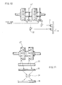
- FIGS 7a and 7b an electromagnetic resonance reading device is shown.
- the decade wheels 14 IV have a magnetic strip which may be coded or not, but is appropriately shaped, either with its width varying continuously or stepped, or shaped in thickness or section.
- Oscillator coils 19 are positioned opposite said strips, which can be cut directly on the metric drums 11 III .
- Each magnetic strip being coupled electromagnetically to the respective resonant circuit 19, determines beats or oscillations on harmonics of the base frequency, which, when appropriately filtered, allow the angular position of the wheel 14 IV or of the drum 11 III to be taken.
- a reading device comprising a look-through optical reader 29 and a light source 27 lighting up from inside the shaft 28 onto which are keyed the coded revolving metric indicators 2′, slotted on their cylindrical surface.
- a reading device is shown composed of proximity sensors 30, which are also magnetic, relating to the metallic, slotted, coded revolving metric indicators 2 ⁇ .
- a reading device is shown composed of light meters 31 which measure the light transmitted by the look-through coded decade wheels 14 V , the light, coming from a source and falling on the decade wheels 14 V , and the light transmitted by the latter being deviated by means of a unit of offset prisms 32.
- a reading device composed of an illuminating led 33 and a unit capable of measuring the light reflected by the coded revolving metric indicators 2′′′, comprising a reflector 35, a lens 34 and an image sensor 36.
Landscapes
- Physics & Mathematics (AREA)
- General Physics & Mathematics (AREA)
- Engineering & Computer Science (AREA)
- Theoretical Computer Science (AREA)
- Arrangements For Transmission Of Measured Signals (AREA)
- Fire-Detection Mechanisms (AREA)
- Lubrication Of Internal Combustion Engines (AREA)
- Color Television Image Signal Generators (AREA)
- Measuring Fluid Pressure (AREA)
- Paper (AREA)
- Length Measuring Devices With Unspecified Measuring Means (AREA)
Priority Applications (1)
| Application Number | Priority Date | Filing Date | Title |
|---|---|---|---|
| AT89830008T ATE88588T1 (de) | 1988-01-18 | 1989-01-10 | Sensoreinrichtung. |
Applications Claiming Priority (2)
| Application Number | Priority Date | Filing Date | Title |
|---|---|---|---|
| IT8819101A IT1215727B (it) | 1988-01-18 | 1988-01-18 | Dispositivo trasduttore perfezionato. |
| IT1910188 | 1988-01-18 |
Publications (2)
| Publication Number | Publication Date |
|---|---|
| EP0325565A1 true EP0325565A1 (de) | 1989-07-26 |
| EP0325565B1 EP0325565B1 (de) | 1993-04-21 |
Family
ID=11154543
Family Applications (1)
| Application Number | Title | Priority Date | Filing Date |
|---|---|---|---|
| EP89830008A Expired - Lifetime EP0325565B1 (de) | 1988-01-18 | 1989-01-10 | Sensoreinrichtung |
Country Status (5)
| Country | Link |
|---|---|
| US (1) | US5010334A (de) |
| EP (1) | EP0325565B1 (de) |
| AT (1) | ATE88588T1 (de) |
| DE (1) | DE68906033T2 (de) |
| IT (1) | IT1215727B (de) |
Cited By (5)
| Publication number | Priority date | Publication date | Assignee | Title |
|---|---|---|---|---|
| EP0939380A1 (de) * | 1998-02-27 | 1999-09-01 | MR Engineering AG | Ausleseeinrichtung für ein Rollenzählwerk |
| US6407377B1 (en) | 1998-02-27 | 2002-06-18 | Mr Engineering Ag | Apparatus for reading-out a setting of number wheels |
| WO2010055181A1 (es) * | 2008-11-11 | 2010-05-20 | Juan Melsom | Dispositivo contador electrónico de valores numéricos accionado manualmente. |
| DE102009003976A1 (de) | 2009-01-07 | 2010-07-08 | Hengstler Gmbh | Vorrichtung zur optischen Abtastung der Teilstriche eines mechanischen Rollenzählwerkes |
| WO2011009970A1 (es) * | 2009-07-23 | 2011-01-27 | Pro Games Ag | Mesa electrónica de póquer |
Families Citing this family (6)
| Publication number | Priority date | Publication date | Assignee | Title |
|---|---|---|---|---|
| US5422466A (en) * | 1992-07-23 | 1995-06-06 | Wako Seiki Kabushiki Kaisha | Revolution indicator for measuring distances |
| CN1147821C (zh) * | 2000-04-23 | 2004-04-28 | 孙小唐 | 机械转轮式计数器及其电子数字化读取方法 |
| JP4358790B2 (ja) * | 2005-06-30 | 2009-11-04 | コンテックス株式会社 | 照明手段内蔵電磁カウンタ |
| EP1993212B1 (de) * | 2007-05-15 | 2010-07-14 | Atmel Automotive GmbH | Wandlervorrichtung |
| CN103499357B (zh) * | 2013-10-24 | 2015-09-30 | 辽宁宏建仪器制造有限公司 | 远传仪表用电信号计数光电直读装置 |
| US9712896B2 (en) * | 2014-12-30 | 2017-07-18 | Acotel Groups S.P.A. | Device and method for reading a meter |
Citations (8)
| Publication number | Priority date | Publication date | Assignee | Title |
|---|---|---|---|---|
| GB858193A (en) * | 1957-08-12 | 1961-01-11 | Edward Butterworth | Improvements in or relating to electrical apparatus for the remote reading of meters |
| FR2159479A1 (de) * | 1971-11-10 | 1973-06-22 | Tri Tech | |
| FR2212081A5 (de) * | 1972-12-22 | 1974-07-19 | Anvar | |
| FR2362368A1 (fr) * | 1976-08-20 | 1978-03-17 | Siemens Ag | Dispositif pour mesurer des quantites de liquide ou de gaz |
| US4199676A (en) * | 1977-02-04 | 1980-04-22 | Hellmut Heuer | Encoder |
| GB2072906A (en) * | 1980-03-27 | 1981-10-07 | Audi Ag | Device for measuring the distance covered by a vehicle |
| EP0205779A2 (de) * | 1985-04-02 | 1986-12-30 | FABBRICHE RIUNITE MISURATORI SACOFGAS S.p.A | Messgeber, dem der Stand von mindestens einem mechanischen Drehelement zugrundeliegt |
| GB2188159A (en) * | 1986-03-19 | 1987-09-23 | Honda Motor Co Ltd | Angle-of-rotation sensor |
Family Cites Families (8)
| Publication number | Priority date | Publication date | Assignee | Title |
|---|---|---|---|---|
| US3017086A (en) * | 1957-12-04 | 1962-01-16 | Magnavox Co | High speed counters |
| US3262108A (en) * | 1961-06-13 | 1966-07-19 | Warner Swasey Co | Analog to digital converter |
| US3310801A (en) * | 1964-05-15 | 1967-03-21 | Hersey Sparling Meter Company | Analog-digital converter for watt-hour meters |
| US3846789A (en) * | 1973-04-06 | 1974-11-05 | Gen Electric | Remote-reading register with error detecting capability |
| US4031386A (en) * | 1976-06-15 | 1977-06-21 | Rockwell International Corporation | Optical transducer encoding apparatus |
| US4426574A (en) * | 1981-12-11 | 1984-01-17 | Veeder Industries Inc. | Fuel pump counter readout |
| GB2187011B (en) * | 1986-02-20 | 1989-11-08 | Smith Meters Ltd | Remote reading of a counting device |
| KR890008726Y1 (ko) * | 1987-02-03 | 1989-11-30 | 최혁 | 원격 검침용 계량기 |
-
1988
- 1988-01-18 IT IT8819101A patent/IT1215727B/it active
-
1989
- 1989-01-10 DE DE8989830008T patent/DE68906033T2/de not_active Expired - Fee Related
- 1989-01-10 EP EP89830008A patent/EP0325565B1/de not_active Expired - Lifetime
- 1989-01-10 AT AT89830008T patent/ATE88588T1/de not_active IP Right Cessation
- 1989-01-17 US US07/297,434 patent/US5010334A/en not_active Expired - Lifetime
Patent Citations (8)
| Publication number | Priority date | Publication date | Assignee | Title |
|---|---|---|---|---|
| GB858193A (en) * | 1957-08-12 | 1961-01-11 | Edward Butterworth | Improvements in or relating to electrical apparatus for the remote reading of meters |
| FR2159479A1 (de) * | 1971-11-10 | 1973-06-22 | Tri Tech | |
| FR2212081A5 (de) * | 1972-12-22 | 1974-07-19 | Anvar | |
| FR2362368A1 (fr) * | 1976-08-20 | 1978-03-17 | Siemens Ag | Dispositif pour mesurer des quantites de liquide ou de gaz |
| US4199676A (en) * | 1977-02-04 | 1980-04-22 | Hellmut Heuer | Encoder |
| GB2072906A (en) * | 1980-03-27 | 1981-10-07 | Audi Ag | Device for measuring the distance covered by a vehicle |
| EP0205779A2 (de) * | 1985-04-02 | 1986-12-30 | FABBRICHE RIUNITE MISURATORI SACOFGAS S.p.A | Messgeber, dem der Stand von mindestens einem mechanischen Drehelement zugrundeliegt |
| GB2188159A (en) * | 1986-03-19 | 1987-09-23 | Honda Motor Co Ltd | Angle-of-rotation sensor |
Cited By (6)
| Publication number | Priority date | Publication date | Assignee | Title |
|---|---|---|---|---|
| EP0939380A1 (de) * | 1998-02-27 | 1999-09-01 | MR Engineering AG | Ausleseeinrichtung für ein Rollenzählwerk |
| US6407377B1 (en) | 1998-02-27 | 2002-06-18 | Mr Engineering Ag | Apparatus for reading-out a setting of number wheels |
| WO2010055181A1 (es) * | 2008-11-11 | 2010-05-20 | Juan Melsom | Dispositivo contador electrónico de valores numéricos accionado manualmente. |
| DE102009003976A1 (de) | 2009-01-07 | 2010-07-08 | Hengstler Gmbh | Vorrichtung zur optischen Abtastung der Teilstriche eines mechanischen Rollenzählwerkes |
| WO2010079129A2 (de) | 2009-01-07 | 2010-07-15 | Hengstler Gmbh | Vorrichtung zur optischen abtastung der teilstriche eines mechanischen rollenzählwerkes |
| WO2011009970A1 (es) * | 2009-07-23 | 2011-01-27 | Pro Games Ag | Mesa electrónica de póquer |
Also Published As
| Publication number | Publication date |
|---|---|
| DE68906033T2 (de) | 1993-08-05 |
| ATE88588T1 (de) | 1993-05-15 |
| DE68906033D1 (de) | 1993-05-27 |
| EP0325565B1 (de) | 1993-04-21 |
| IT8819101A0 (it) | 1988-01-18 |
| IT1215727B (it) | 1990-02-22 |
| US5010334A (en) | 1991-04-23 |
Similar Documents
| Publication | Publication Date | Title |
|---|---|---|
| KR100360511B1 (ko) | 체적측정계기용다자리수계수휠기구 | |
| US5010334A (en) | Transducer device | |
| CA2057884C (en) | Digitial linear measuring device | |
| CA1103357A (en) | Meter dial encoder for remote meter reading | |
| EP0783675B1 (de) | Apparat zur drehmomentmessung von rotierenden wellen | |
| US5483831A (en) | Direct liquid level reading device | |
| US4740690A (en) | Absolute combinational encoders coupled through a fixed gear ratio | |
| US4117320A (en) | Digital measuring instruments | |
| SU1034619A3 (ru) | Устройство дл измерени угла или угловой скорости | |
| US4321531A (en) | Direction sensitive pulse initiator for a wattmeter | |
| US4803484A (en) | Optically readable and human readable dial | |
| US7406772B2 (en) | Device for measuring the position, the path or the rotational angle of an object | |
| US3944821A (en) | Detection of angular position | |
| US5045691A (en) | Opto-electronic system for measuring and displaying rotary movement | |
| US3326077A (en) | Optical device employing multiple slit patterns for zero reference in a shaft encoder | |
| CN204007757U (zh) | 计量表读数字轮 | |
| EP0344931A2 (de) | Zähler | |
| CA1225151A (en) | Apparatus for digital angular measurement | |
| JP3545120B2 (ja) | 積算回転数計測装置及び積算回転数計測方法 | |
| US5422466A (en) | Revolution indicator for measuring distances | |
| EP0205779B1 (de) | Messgeber, dem der Stand von mindestens einem mechanischen Drehelement zugrundeliegt | |
| US3660830A (en) | Multi-element shaft encoder incorporating a geneva drive | |
| US6181423B1 (en) | Linear encoder providing engagement by engraving | |
| US2829833A (en) | Azimuth counter | |
| JPH0427488B2 (de) |
Legal Events
| Date | Code | Title | Description |
|---|---|---|---|
| PUAI | Public reference made under article 153(3) epc to a published international application that has entered the european phase |
Free format text: ORIGINAL CODE: 0009012 |
|
| AK | Designated contracting states |
Kind code of ref document: A1 Designated state(s): AT BE CH DE ES FR GB GR IT LI LU NL SE |
|
| 17P | Request for examination filed |
Effective date: 19900104 |
|
| 17Q | First examination report despatched |
Effective date: 19911211 |
|
| GRAA | (expected) grant |
Free format text: ORIGINAL CODE: 0009210 |
|
| AK | Designated contracting states |
Kind code of ref document: B1 Designated state(s): AT BE CH DE ES FR GB GR IT LI LU NL SE |
|
| PG25 | Lapsed in a contracting state [announced via postgrant information from national office to epo] |
Ref country code: SE Effective date: 19930421 Ref country code: NL Effective date: 19930421 Ref country code: LI Effective date: 19930421 Ref country code: GR Free format text: LAPSE BECAUSE OF FAILURE TO SUBMIT A TRANSLATION OF THE DESCRIPTION OR TO PAY THE FEE WITHIN THE PRESCRIBED TIME-LIMIT Effective date: 19930421 Ref country code: ES Free format text: THE PATENT HAS BEEN ANNULLED BY A DECISION OF A NATIONAL AUTHORITY Effective date: 19930421 Ref country code: CH Effective date: 19930421 Ref country code: BE Effective date: 19930421 Ref country code: AT Effective date: 19930421 |
|
| REF | Corresponds to: |
Ref document number: 88588 Country of ref document: AT Date of ref document: 19930515 Kind code of ref document: T |
|
| ITF | It: translation for a ep patent filed | ||
| REF | Corresponds to: |
Ref document number: 68906033 Country of ref document: DE Date of ref document: 19930527 |
|
| ET | Fr: translation filed | ||
| REG | Reference to a national code |
Ref country code: CH Ref legal event code: PL |
|
| NLV1 | Nl: lapsed or annulled due to failure to fulfill the requirements of art. 29p and 29m of the patents act | ||
| PG25 | Lapsed in a contracting state [announced via postgrant information from national office to epo] |
Ref country code: LU Free format text: LAPSE BECAUSE OF NON-PAYMENT OF DUE FEES Effective date: 19940131 |
|
| PLBE | No opposition filed within time limit |
Free format text: ORIGINAL CODE: 0009261 |
|
| STAA | Information on the status of an ep patent application or granted ep patent |
Free format text: STATUS: NO OPPOSITION FILED WITHIN TIME LIMIT |
|
| 26N | No opposition filed | ||
| REG | Reference to a national code |
Ref country code: GB Ref legal event code: IF02 |
|
| PGFP | Annual fee paid to national office [announced via postgrant information from national office to epo] |
Ref country code: GB Payment date: 20050105 Year of fee payment: 17 |
|
| PGFP | Annual fee paid to national office [announced via postgrant information from national office to epo] |
Ref country code: FR Payment date: 20050113 Year of fee payment: 17 |
|
| PGFP | Annual fee paid to national office [announced via postgrant information from national office to epo] |
Ref country code: DE Payment date: 20050317 Year of fee payment: 17 |
|
| PG25 | Lapsed in a contracting state [announced via postgrant information from national office to epo] |
Ref country code: GB Free format text: LAPSE BECAUSE OF NON-PAYMENT OF DUE FEES Effective date: 20060110 |
|
| PG25 | Lapsed in a contracting state [announced via postgrant information from national office to epo] |
Ref country code: FR Free format text: LAPSE BECAUSE OF NON-PAYMENT OF DUE FEES Effective date: 20060131 |
|
| PGFP | Annual fee paid to national office [announced via postgrant information from national office to epo] |
Ref country code: IT Payment date: 20060131 Year of fee payment: 18 |
|
| PG25 | Lapsed in a contracting state [announced via postgrant information from national office to epo] |
Ref country code: DE Free format text: LAPSE BECAUSE OF NON-PAYMENT OF DUE FEES Effective date: 20060801 |
|
| GBPC | Gb: european patent ceased through non-payment of renewal fee |
Effective date: 20060110 |
|
| REG | Reference to a national code |
Ref country code: FR Ref legal event code: ST Effective date: 20060929 |
|
| PG25 | Lapsed in a contracting state [announced via postgrant information from national office to epo] |
Ref country code: IT Free format text: LAPSE BECAUSE OF NON-PAYMENT OF DUE FEES Effective date: 20070110 |