EP0325729B1 - Klappengestänge für Drehklappen - Google Patents
Klappengestänge für Drehklappen Download PDFInfo
- Publication number
- EP0325729B1 EP0325729B1 EP88119840A EP88119840A EP0325729B1 EP 0325729 B1 EP0325729 B1 EP 0325729B1 EP 88119840 A EP88119840 A EP 88119840A EP 88119840 A EP88119840 A EP 88119840A EP 0325729 B1 EP0325729 B1 EP 0325729B1
- Authority
- EP
- European Patent Office
- Prior art keywords
- levers
- hubs
- axes
- articulated
- springs
- Prior art date
- Legal status (The legal status is an assumption and is not a legal conclusion. Google has not performed a legal analysis and makes no representation as to the accuracy of the status listed.)
- Expired - Lifetime
Links
- 230000005540 biological transmission Effects 0.000 abstract description 3
- 238000005452 bending Methods 0.000 description 3
- 230000000712 assembly Effects 0.000 description 2
- 238000000429 assembly Methods 0.000 description 2
- UGFAIRIUMAVXCW-UHFFFAOYSA-N Carbon monoxide Chemical compound [O+]#[C-] UGFAIRIUMAVXCW-UHFFFAOYSA-N 0.000 description 1
- 239000000428 dust Substances 0.000 description 1
- 239000003546 flue gas Substances 0.000 description 1
- 230000036316 preload Effects 0.000 description 1
Images


Classifications
-
- F—MECHANICAL ENGINEERING; LIGHTING; HEATING; WEAPONS; BLASTING
- F16—ENGINEERING ELEMENTS AND UNITS; GENERAL MEASURES FOR PRODUCING AND MAINTAINING EFFECTIVE FUNCTIONING OF MACHINES OR INSTALLATIONS; THERMAL INSULATION IN GENERAL
- F16K—VALVES; TAPS; COCKS; ACTUATING-FLOATS; DEVICES FOR VENTING OR AERATING
- F16K1/00—Lift valves or globe valves, i.e. cut-off apparatus with closure members having at least a component of their opening and closing motion perpendicular to the closing faces
- F16K1/16—Lift valves or globe valves, i.e. cut-off apparatus with closure members having at least a component of their opening and closing motion perpendicular to the closing faces with pivoted closure-members
- F16K1/18—Lift valves or globe valves, i.e. cut-off apparatus with closure members having at least a component of their opening and closing motion perpendicular to the closing faces with pivoted closure-members with pivoted discs or flaps
- F16K1/22—Lift valves or globe valves, i.e. cut-off apparatus with closure members having at least a component of their opening and closing motion perpendicular to the closing faces with pivoted closure-members with pivoted discs or flaps with axis of rotation crossing the valve member, e.g. butterfly valves
- F16K1/221—Lift valves or globe valves, i.e. cut-off apparatus with closure members having at least a component of their opening and closing motion perpendicular to the closing faces with pivoted closure-members with pivoted discs or flaps with axis of rotation crossing the valve member, e.g. butterfly valves specially adapted operating means therefor
-
- F—MECHANICAL ENGINEERING; LIGHTING; HEATING; WEAPONS; BLASTING
- F24—HEATING; RANGES; VENTILATING
- F24F—AIR-CONDITIONING; AIR-HUMIDIFICATION; VENTILATION; USE OF AIR CURRENTS FOR SCREENING
- F24F13/00—Details common to, or for air-conditioning, air-humidification, ventilation or use of air currents for screening
- F24F13/08—Air-flow control members, e.g. louvres, grilles, flaps or guide plates
- F24F13/10—Air-flow control members, e.g. louvres, grilles, flaps or guide plates movable, e.g. dampers
- F24F13/14—Air-flow control members, e.g. louvres, grilles, flaps or guide plates movable, e.g. dampers built up of tilting members, e.g. louvre
- F24F13/15—Air-flow control members, e.g. louvres, grilles, flaps or guide plates movable, e.g. dampers built up of tilting members, e.g. louvre with parallel simultaneously tiltable lamellae
-
- Y—GENERAL TAGGING OF NEW TECHNOLOGICAL DEVELOPMENTS; GENERAL TAGGING OF CROSS-SECTIONAL TECHNOLOGIES SPANNING OVER SEVERAL SECTIONS OF THE IPC; TECHNICAL SUBJECTS COVERED BY FORMER USPC CROSS-REFERENCE ART COLLECTIONS [XRACs] AND DIGESTS
- Y10—TECHNICAL SUBJECTS COVERED BY FORMER USPC
- Y10T—TECHNICAL SUBJECTS COVERED BY FORMER US CLASSIFICATION
- Y10T74/00—Machine element or mechanism
- Y10T74/18—Mechanical movements
- Y10T74/18856—Oscillating to oscillating
-
- Y—GENERAL TAGGING OF NEW TECHNOLOGICAL DEVELOPMENTS; GENERAL TAGGING OF CROSS-SECTIONAL TECHNOLOGIES SPANNING OVER SEVERAL SECTIONS OF THE IPC; TECHNICAL SUBJECTS COVERED BY FORMER USPC CROSS-REFERENCE ART COLLECTIONS [XRACs] AND DIGESTS
- Y10—TECHNICAL SUBJECTS COVERED BY FORMER USPC
- Y10T—TECHNICAL SUBJECTS COVERED BY FORMER US CLASSIFICATION
- Y10T74/00—Machine element or mechanism
- Y10T74/20—Control lever and linkage systems
- Y10T74/20006—Resilient connections
Definitions
- the invention relates to a valve linkage for a plurality of rotary flaps mounted on a flap frame in parallel axes, the rotary flap shafts of which have hubs connected in a rotationally fixed manner at their ends and straight double-arm articulated levers connected to the middle, on which rigid push rods of an actuator act, the articulated levers being articulated about pivot axes on their hubs in such a way are mounted that the pivot axes run parallel to a line intersecting the axes of rotation of the push rods on the articulated levers and the respective rotary valve shaft can be pivoted about the pivot axis against the plane of the articulated lever.
- Such a valve rod assembly is known in which the rotary valve shafts are kept free of bending moments even when the length of the valve frame changes due to temperature or the distance of the rotary valve shafts.
- slight leaks can occur when a plurality of rotary flaps are arranged, although all rotary flaps are adjusted uniformly with the known valve linkage. In particular, these leaks. then occur when there are dust deposits in the area of the valve seats (cf. DE-A 22 44 972).
- the invention has for its object to provide a valve linkage of the type described above, which ensures a complete closure of all rotary flaps.
- two springs are symmetrically assigned to the rotary valve shafts.
- the axes of the springs are perpendicular to the longitudinal axes of the articulated levers. This results in a load of the springs free of bending moment, so that the spring characteristics remain unaffected by such moments.
- the springs are designed as plate spring assemblies, uneven wear of the plate springs is avoided.
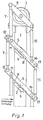
- a flap linkage for a plurality of rotary flaps embedded in a flap frame is shown.
- Rotary flaps of this type are used in particular in ducts with a large cross section, for example in flue gas ducts in power plants.
- the valve linkage has a gear 2 and rotary valve shafts 3 mounted on the valve frame 1.
- Articulated levers 5 are connected to the ends of the rotary valve shafts 3 in a manner described below.
- the articulated levers 5 are among one another connected to one another via connecting rods 7, 15.
- the respective outer and upper push rods 7, 15 are articulated to a drive lever 9 belonging to the transmission 2.
- the push rods 7, 15 are rigid push rods, the arrangement being such that the pivot axes 8 of the articulated levers 5 run parallel to a line which defines the axes of rotation 11, 12, 16, 17 of the push rods 7, 15 on the articulated levers 5 cuts.
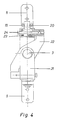
- the connection of the rotary valve shafts 3 to the articulated levers 5 takes place in such a way that the articulated shaft 3 can be pivoted about a pivot axis 8 against the plane of the articulated lever 5.
- the bearings 18 used for this purpose are arranged in supports 19 which are fastened on the articulated levers 5.
- pins 20 are guided, with which intermediate levers 21 are connected, which are mounted on the rotary valve shafts 3 but are not connected to them in a rotationally fixed manner.
- Hubs 4, 22 are non-rotatably connected to the rotary valve shafts 3 and are supported against the intermediate levers 21 by springs 23.
- These springs 23 are plate spring assemblies, the preload of which can be adjusted by means of screws 24.
Landscapes
- Engineering & Computer Science (AREA)
- General Engineering & Computer Science (AREA)
- Mechanical Engineering (AREA)
- Chemical & Material Sciences (AREA)
- Combustion & Propulsion (AREA)
- Lift Valve (AREA)
- Mechanically-Actuated Valves (AREA)
- Push-Button Switches (AREA)
- Spinning Or Twisting Of Yarns (AREA)
- Nitrogen Condensed Heterocyclic Rings (AREA)
- Operating, Guiding And Securing Of Roll- Type Closing Members (AREA)
- Specific Sealing Or Ventilating Devices For Doors And Windows (AREA)
- Dc-Dc Converters (AREA)
- Measuring Pulse, Heart Rate, Blood Pressure Or Blood Flow (AREA)
Priority Applications (1)
| Application Number | Priority Date | Filing Date | Title |
|---|---|---|---|
| AT88119840T ATE89380T1 (de) | 1987-11-30 | 1988-11-29 | Klappengestaenge fuer drehklappen. |
Applications Claiming Priority (2)
| Application Number | Priority Date | Filing Date | Title |
|---|---|---|---|
| DE8715838U | 1987-11-30 | ||
| DE8715838 | 1987-11-30 |
Publications (3)
| Publication Number | Publication Date |
|---|---|
| EP0325729A2 EP0325729A2 (de) | 1989-08-02 |
| EP0325729A3 EP0325729A3 (en) | 1990-07-11 |
| EP0325729B1 true EP0325729B1 (de) | 1993-05-12 |
Family
ID=6814607
Family Applications (1)
| Application Number | Title | Priority Date | Filing Date |
|---|---|---|---|
| EP88119840A Expired - Lifetime EP0325729B1 (de) | 1987-11-30 | 1988-11-29 | Klappengestänge für Drehklappen |
Country Status (6)
| Country | Link |
|---|---|
| US (1) | US4977791A (da) |
| EP (1) | EP0325729B1 (da) |
| AT (1) | ATE89380T1 (da) |
| DE (1) | DE3881018D1 (da) |
| DK (1) | DK666788A (da) |
| FI (1) | FI885468A7 (da) |
Families Citing this family (16)
| Publication number | Priority date | Publication date | Assignee | Title |
|---|---|---|---|---|
| US5083453A (en) * | 1990-02-01 | 1992-01-28 | Mts Systems Corporation | Linkage for vehicle simulator |
| DE4107175A1 (de) * | 1991-03-06 | 1992-09-10 | Mannesmann Ag | Vorrichtung zum absperren grosser rohrleitungen |
| US5277076A (en) * | 1992-06-08 | 1994-01-11 | Ball Corporation | Reactionless scan mechanism |
| US5465615A (en) * | 1994-04-28 | 1995-11-14 | Mts Systems Corporation | Loading assembly for a vehicle spindle test fixture |
| US5533403A (en) * | 1994-11-10 | 1996-07-09 | Mts Systems Corporation | Loading assembly for a vehicle spindle test fixture |
| US5749703A (en) * | 1995-05-19 | 1998-05-12 | Stober + Morlock Warmekraft Gesellschaft Mbh | Shaft assembly for gas control flap in a gas turbine |
| EP1160511B1 (en) | 1998-08-03 | 2013-01-02 | Mitsubishi Heavy Industries, Ltd. | Gas turbine combustor by-pass valve device |
| US6135414A (en) * | 1998-12-24 | 2000-10-24 | Whittaker Corporation | Ball valve apparatus |
| US6257055B1 (en) | 1999-05-04 | 2001-07-10 | Mts Systems Corporation | Loading assembly for a vehicle spindle test fixture |
| US6640638B1 (en) | 1999-09-03 | 2003-11-04 | Mts Systems Corporation | Loading assembly for a vehicle spindle test fixture |
| RU2188354C2 (ru) * | 2000-09-11 | 2002-08-27 | Опытное конструкторское бюро машиностроения | Клапан |
| EP2423544A3 (en) * | 2010-08-26 | 2014-12-17 | Parker Hannifin Corporation | Rotary valve |
| EP2700885B1 (de) * | 2012-08-25 | 2015-06-17 | CB-tec GmbH | Zuluft-Wanddurchführung |
| US12130423B1 (en) | 2020-08-12 | 2024-10-29 | Bae Systems Space & Mission Systems Inc. | Two degree-of freedom reactionless pointing and scanning system |
| US12320466B2 (en) | 2021-03-10 | 2025-06-03 | Bae Systems Space & Mission Systems Inc. | Systems and methods for limiting rotation of a supported object |
| US12313905B1 (en) | 2022-03-15 | 2025-05-27 | Bae Systems Space & Mission Systems Inc. | Monolithic two-axis flexure with center hole feature |
Citations (1)
| Publication number | Priority date | Publication date | Assignee | Title |
|---|---|---|---|---|
| DE2244972C2 (de) * | 1972-07-01 | 1988-11-10 | Morlock, Werner, Dipl.Ing., 4350 Recklinghausen | Klappengestänge für Drehklappen |
Family Cites Families (7)
| Publication number | Priority date | Publication date | Assignee | Title |
|---|---|---|---|---|
| US2708093A (en) * | 1952-12-22 | 1955-05-10 | Leber Felix | Valve operating means with electromagnetic blocking means |
| US3307583A (en) * | 1964-05-01 | 1967-03-07 | Atlantic Res Corp | Valve actuating means |
| US4236422A (en) * | 1979-08-01 | 1980-12-02 | J. I. Case Company | Fluid pump control system for a tractor |
| DE3023639A1 (de) * | 1980-06-24 | 1982-01-21 | Janich, geb.Fischer, Elsbeth, 4720 Beckum | Vorrichtung zum absperren grosser rohrleitungen |
| EP0049302A1 (en) * | 1980-10-06 | 1982-04-14 | Combustion Engineering, Inc. | System for controlling the flow of gaseous fluids |
| DE3313662A1 (de) * | 1983-04-15 | 1984-10-18 | Hermann Rappold & Co GmbH, 5160 Düren | Mehrklappenventil fuer heisse gase |
| US4610197A (en) * | 1985-06-12 | 1986-09-09 | Philips Industrial Components, Inc. | Damper blade construction |
-
1988
- 1988-11-24 FI FI885468A patent/FI885468A7/fi not_active IP Right Cessation
- 1988-11-29 AT AT88119840T patent/ATE89380T1/de not_active IP Right Cessation
- 1988-11-29 DK DK666788A patent/DK666788A/da not_active Application Discontinuation
- 1988-11-29 DE DE8888119840T patent/DE3881018D1/de not_active Expired - Lifetime
- 1988-11-29 EP EP88119840A patent/EP0325729B1/de not_active Expired - Lifetime
- 1988-11-30 US US07/277,807 patent/US4977791A/en not_active Expired - Lifetime
Patent Citations (1)
| Publication number | Priority date | Publication date | Assignee | Title |
|---|---|---|---|---|
| DE2244972C2 (de) * | 1972-07-01 | 1988-11-10 | Morlock, Werner, Dipl.Ing., 4350 Recklinghausen | Klappengestänge für Drehklappen |
Also Published As
| Publication number | Publication date |
|---|---|
| EP0325729A3 (en) | 1990-07-11 |
| FI885468A7 (fi) | 1989-05-31 |
| DK666788D0 (da) | 1988-11-29 |
| US4977791A (en) | 1990-12-18 |
| DK666788A (da) | 1989-05-31 |
| EP0325729A2 (de) | 1989-08-02 |
| DE3881018D1 (de) | 1993-06-17 |
| ATE89380T1 (de) | 1993-05-15 |
| FI885468A0 (fi) | 1988-11-24 |
Similar Documents
| Publication | Publication Date | Title |
|---|---|---|
| EP0325729B1 (de) | Klappengestänge für Drehklappen | |
| DE3618331C2 (de) | Betätigungshebel für ein Paar gleichzeitig verstellbarer Leitschaufeln | |
| DE102007016554A1 (de) | Absperrsystem für große Leitungsquerschnitte mit einer Schwenkklappe | |
| CH671195A5 (da) | ||
| DE2412098C2 (de) | Strömungsverteiler für eine Fahrzeug-Belüftungs-, Heizungs- oder -Klimaanlage | |
| EP0042492B1 (de) | Vorrichtung zum Absperren grosser Rohrleitungen | |
| EP0048799A1 (de) | Rotor eines Drehflügelflugzeugs | |
| DE3400703C2 (de) | Konvergent-divergente Düse, insbesondere für ein Strahltriebwerk | |
| EP1148297B1 (de) | Klappe, insbesondere Umschaltklappe für grosse Kanalquerschnitte | |
| EP0407335B1 (de) | Webmaschine mit schwenkbarem Betätigungswerkzeug für Schaftkupplungen | |
| DE2414919A1 (de) | Betaetigungseinrichtung fuer die lenkhilfe eines lenkgetriebes von kraftfahrzeugen | |
| DE2929896C2 (de) | Vorrichtung zum Kuppeln zweier Drehgestelle eines Schienenfahrzeuges | |
| DE2244972C2 (de) | Klappengestänge für Drehklappen | |
| DE3637734A1 (de) | Vorrichtung zum absperren grosser heissgas-rohrleitungen | |
| DE2226986C3 (de) | Drosselklappenventil | |
| EP0502593B1 (de) | Vorrichtung zum Absperren grosser Rohrleitungen | |
| DE2012048C3 (de) | Schienengliederfahrzeug | |
| DE3313662C2 (da) | ||
| DE8814818U1 (de) | Klappengestänge für Drehklappen | |
| DE3521636C2 (da) | ||
| DE102018114745A1 (de) | Horizontale Mittenrückstellung für eine Mittelpufferkupplung | |
| DE2441079C3 (de) | Drosselklappenventil | |
| DE1455185C (de) | Mehrteiliges Schienen-Gelenkfahrzeug | |
| DE1270424B (de) | Dreiwege-Drehflachschieber zur Hoehenregelung fuer eine pneumatische Fahrzeugfederung | |
| DE3435914A1 (de) | Klappenventilanordnung fuer eine rohrleitung, durch welche gase mit hoher geschwindigkeit stroemen |
Legal Events
| Date | Code | Title | Description |
|---|---|---|---|
| PUAI | Public reference made under article 153(3) epc to a published international application that has entered the european phase |
Free format text: ORIGINAL CODE: 0009012 |
|
| AK | Designated contracting states |
Kind code of ref document: A2 Designated state(s): AT BE CH DE ES FR GB GR IT LI LU NL SE |
|
| RIN1 | Information on inventor provided before grant (corrected) |
Inventor name: VON ERICHSEN, VOLKER |
|
| RBV | Designated contracting states (corrected) |
Designated state(s): AT BE CH DE FR GB IT LI LU NL SE |
|
| 17P | Request for examination filed |
Effective date: 19891111 |
|
| PUAL | Search report despatched |
Free format text: ORIGINAL CODE: 0009013 |
|
| AK | Designated contracting states |
Kind code of ref document: A3 Designated state(s): AT BE CH DE FR GB IT LI LU NL SE |
|
| 17Q | First examination report despatched |
Effective date: 19920109 |
|
| GRAA | (expected) grant |
Free format text: ORIGINAL CODE: 0009210 |
|
| AK | Designated contracting states |
Kind code of ref document: B1 Designated state(s): AT BE CH DE FR GB IT LI LU NL SE |
|
| PG25 | Lapsed in a contracting state [announced via postgrant information from national office to epo] |
Ref country code: IT Free format text: LAPSE BECAUSE OF FAILURE TO SUBMIT A TRANSLATION OF THE DESCRIPTION OR TO PAY THE FEE WITHIN THE PRE;WARNING: LAPSES OF ITALIAN PATENTS WITH EFFECTIVE DATE BEFORE 2007 MAY HAVE OCCURRED AT ANY TIME BEFORE 2007. THE CORRECT EFFECTIVE DATE MAY BE DIFFERENT FROM THE ONE RECORDED.SCRIBED TIME-LIMIT Effective date: 19930512 Ref country code: BE Effective date: 19930512 Ref country code: SE Effective date: 19930512 |
|
| REF | Corresponds to: |
Ref document number: 89380 Country of ref document: AT Date of ref document: 19930515 Kind code of ref document: T |
|
| REF | Corresponds to: |
Ref document number: 3881018 Country of ref document: DE Date of ref document: 19930617 |
|
| ET | Fr: translation filed | ||
| GBT | Gb: translation of ep patent filed (gb section 77(6)(a)/1977) |
Effective date: 19930524 |
|
| PGFP | Annual fee paid to national office [announced via postgrant information from national office to epo] |
Ref country code: AT Payment date: 19931123 Year of fee payment: 6 |
|
| PG25 | Lapsed in a contracting state [announced via postgrant information from national office to epo] |
Ref country code: LI Effective date: 19931130 Ref country code: CH Effective date: 19931130 Ref country code: LU Free format text: LAPSE BECAUSE OF NON-PAYMENT OF DUE FEES Effective date: 19931130 |
|
| PGFP | Annual fee paid to national office [announced via postgrant information from national office to epo] |
Ref country code: NL Payment date: 19931130 Year of fee payment: 6 |
|
| PG25 | Lapsed in a contracting state [announced via postgrant information from national office to epo] |
Ref country code: FR Effective date: 19940729 |
|
| REG | Reference to a national code |
Ref country code: CH Ref legal event code: PL |
|
| REG | Reference to a national code |
Ref country code: FR Ref legal event code: ST |
|
| PG25 | Lapsed in a contracting state [announced via postgrant information from national office to epo] |
Ref country code: AT Effective date: 19941129 |
|
| PG25 | Lapsed in a contracting state [announced via postgrant information from national office to epo] |
Ref country code: NL Effective date: 19950601 |
|
| NLV4 | Nl: lapsed or anulled due to non-payment of the annual fee | ||
| PGFP | Annual fee paid to national office [announced via postgrant information from national office to epo] |
Ref country code: GB Payment date: 19960916 Year of fee payment: 9 |
|
| PG25 | Lapsed in a contracting state [announced via postgrant information from national office to epo] |
Ref country code: GB Free format text: LAPSE BECAUSE OF NON-PAYMENT OF DUE FEES Effective date: 19971129 |
|
| GBPC | Gb: european patent ceased through non-payment of renewal fee |
Effective date: 19971129 |
|
| PGFP | Annual fee paid to national office [announced via postgrant information from national office to epo] |
Ref country code: DE Payment date: 20080118 Year of fee payment: 20 |
|
| PLBE | No opposition filed within time limit |
Free format text: ORIGINAL CODE: 0009261 |
|
| STAA | Information on the status of an ep patent application or granted ep patent |
Free format text: STATUS: NO OPPOSITION FILED WITHIN TIME LIMIT |